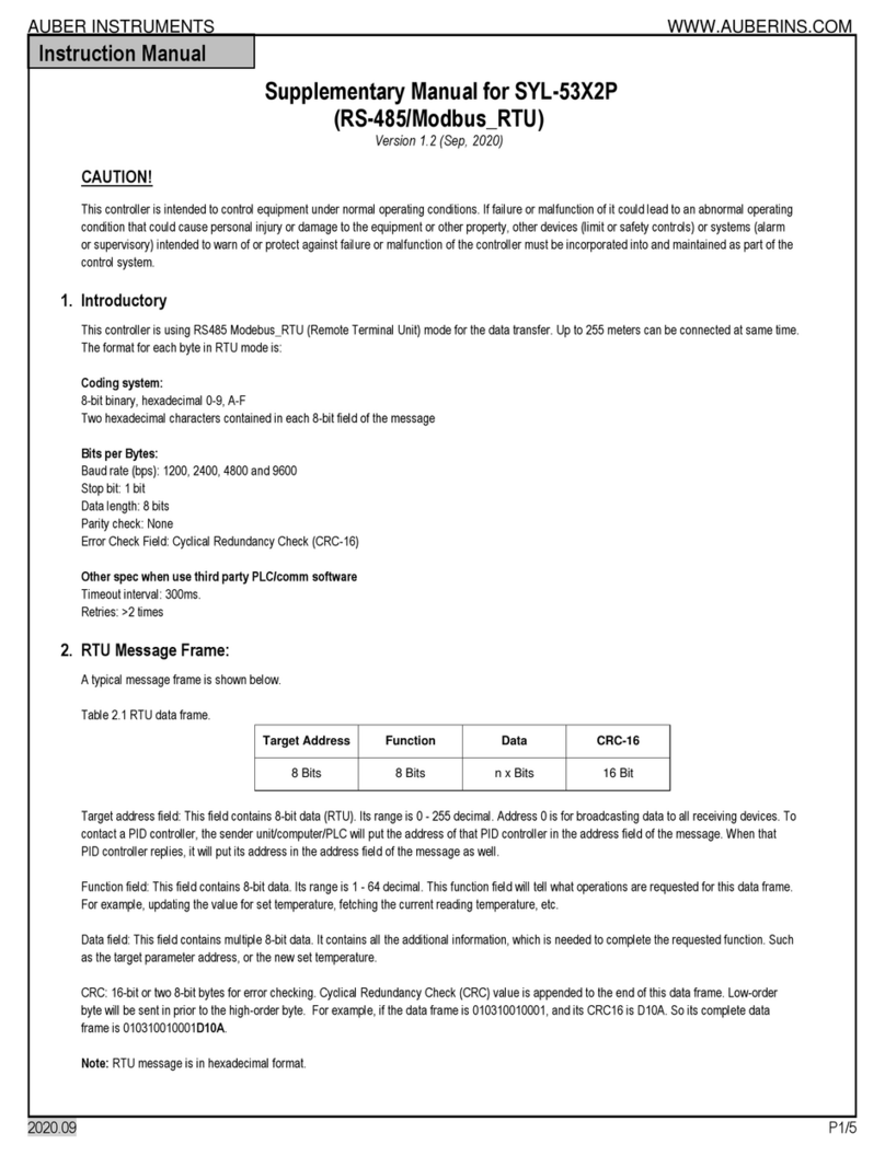
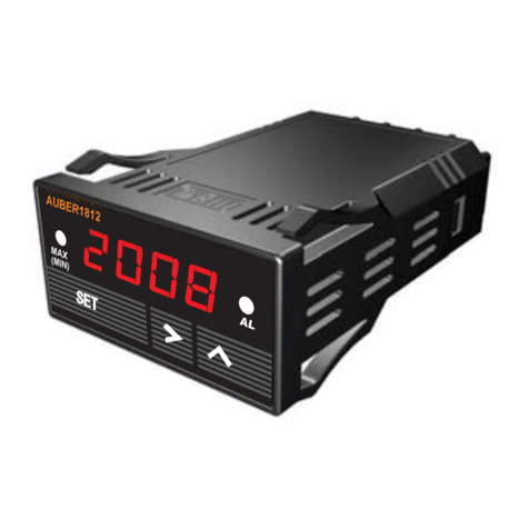
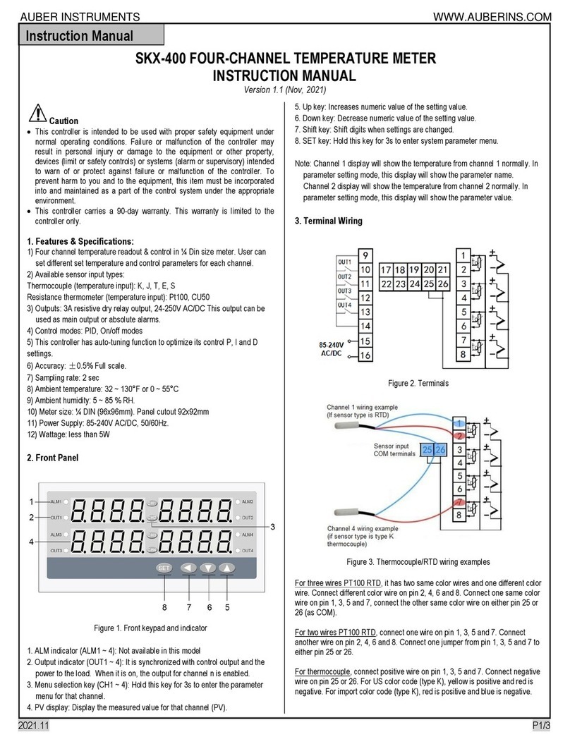
Auber Instruments SYL-1813-MR User manual

AUBER INSTRUMENTS WWW.AUBERINS.COM
2021.05 P1/3
SYL-1813-MR Multifunction Automotive Gauge
Version 1.2 (May 2021)
A. Specifications
•Power supply: 12 V DC (isolated)
•Power consumption: < 2 W
•Sampling rate: 4 samples/second
•Accuracy: 0.2% full scale ±1
•Display range: -1999 ~9999
•Relay contact rating: 3 A @ 220 VAC
•Overall dimensions: 60 x 60 x 59 mm
•Mounting cutout dimension: 55 mm (2 1/16 inch)
•LED display: 0.28’’ red color
•Working condition: 0 ~ 50 ˚C, ≤85% RH
B. Front Panel
Figure 1. Front panel of SYL-1813-MR.
①Display window
②Maximum and Minimum value indicator
③Alarm and relay J1 indicator
④Set key
⑤Shift key
⑥Up key
Description
1. LED display window to show readings from the sensor.
2. MAX (MIN) on when Display window shows the maximum value or the time of
the Max. MAX (MIN) blinking when Display window shows the minimum value or
the time of Min.
3. AL on indicates alarm is on and J1 relay is pulled in (closed).
4. Set key. To enter parameter setting mode, and to select or save parameters.
5. Shift key (“>”). In the parameter setting mode, press this key to select the digit
to be changed. In the normal operation mode, press this key to change the
display in the sequence as shown in the diagram below. Please note that time is
expressed in Hour.Minute (hh.mm) format.
6. Up key (“Λ”). In the parameter setting mode, press it to increase the displayed
value. When displaying Max/Min, press and hold it for 3 seconds to clear the
Max/Min stored. In normal function, this key has two functions, show operation
time and change display brightness. Press and hold it down to show the
operation time since on. Release the key to show the current temperature
(process value). Each time the key is pressed, the display brightness will also be
changed from bright to dim or from dim to bright.
XXX.X
Process Value
(PV)
MAX (MIN) off
XXX.X
Maximum
(MAX)
MAX (MIN) on
XX.XX
Time for Max
(MA_t)
MAX (MIN) on
XX.XX
Time for Min
(MI_t)
MAX (MIN) blink
XXX.X
Minimum
(MI)
MAX (MIN) blink
>Key >Key
>Key>Key
>Key
Figure 2. Check the peak values on the gauge by pressing Shift key.
C. Terminal Assignment
-+
J1 Output
+ mV mA -
Regulated
+5VDC
678910
54321
Power
12VDC
+ TC -
R
+ V -
Figure 3. Terminal assignment of SYL-1813 gauge.
Description
1. Terminal 1 and 2 are for power input.
2. Terminal 3 is for display brightness control. When connecting the
illumination signal (+12 V) to it, the brightness with synchronized with headlight.
If not connected, the brightness can still be controlled by “Λ” up key.
3. Terminal 4 and 5 are for alarm relay output. See Application example 1
below for how to use it.
4. Terminal 6, 7, 8, and 9 are for different types of input signal. Use 6 and 7 for
thermocouple input. Use 6, 7, and 8 for RTD sensor input. Use 6 and 9 for
pressure sensor.
5. Terminal 10 supplies a regulated +5VDC for powering pressure transducer.
D. Parameter Setting
D.1 Basic parameter (press (set) then input code 0089 to enter)
D.1.A) Basic parameter description
Symbol
Name
Description
Setting Range
Initial
Setting
Note
Inty
Inty
Input Type
See Table 1
k
Dot
Dot
Decimal Point
0000 ~ 00.00
00.00
1
Pul
Pul
Scale Low
-1999 ~ 9999
00.00
PuH
PuH
Scale High
-1999 ~ 9999
03.15
Psb
Psb
Zero offset
-1000 ~ 1000
0
2
PSbF
PSbF
Range Coefficient
0.500 ~ 2.000
1.000
3
CorF
CorF
Temperature Unit
C: ˚C; F: ˚F
F
FILT
FILT
Digital Filter
0 ~ 3
0
4
End
End
Exit
Note 1. These parameters define the scale boundary and resolution of the
display value. They do not apply to temperature sensors.
Note 2. For correcting the offset at zero: Display = measurement + PSb.
This parameter only applies to temperature sensors.
Instruction Manual

AUBER INSTRUMENTS WWW.AUBERINS.COM
2021.05 P2/3
Note 3. For adjusting the display value; applies only to the temperature
readings. Display = measurement * PSbF.
Note 4. Digital filter. Filt = 0, no filter; 1, weak; 2, medium; 3, strong.
Table 1. Sensor Input Type Options
Symbol
Input Type
Range
Res.
Accy.
Impedance
T
TC, Type T
-200 ~ 400°C
1°C(° F)
0.3%
100K
R
TC, Type R
-50 ~ 1600°C
1°C(° F)
0.3%
100K
J
TC, Type J
-200 ~ 1200°C
1°C(° F)
0.2%
100K
WRE
TC, WRe3
–WRe25
0 ~ 2300°C
1°C(° F)
0.2%
100K
Vdo
VDO
water/oil
Temp
50 ~ 150°C
1°C(° F)
0.3%
(0.2mA)
S
TC, Type S
-50 ~ 1600°C
1°C(° F)
0.3%
100K
K
TC, Type K
-200 ~ 1300°C
1°C(° F)
0.2%
100K
E
TC, Type E
-200 ~ 900°C
1°C(° F)
0.2%
100K
P100
RTD,
PT100
-200 ~ 600°C
1°C(° F)
0.2%
(0.2mA)
Cu50
RTD, Cu50
-50.0~ 150.0°C
0.1°C
(° F)
0.5%
(0.2mA)
375r
0~375Ω
Pressure
Display range
can be set
to -1999 ~ 9999
16 bit A/D
0.2%
(0.2mA)
75mV
0~75mV
Current
0.1%
100K
30mV
0~30mV
0.1%
100K
5V
0~5V
0.1%
100K
1-5V
1~5V
0.1%
100K
10V
10V
0.1%
100K
10mA
0~10mA
0.3%
150Ω
20mA
0~20mA
0.2%
150Ω
4 -–
20mA
4~20mA
0.2%
150Ω
(Note: TC, thermocouples.)
D.1.B) How to change basic parameters (see Figure 4)
Operation Mode
0089
Enter Code
Symbol
Input Low Limit
inty
XXXX
XXXX
XXXX
PuL
DOT
psb
Input High Limit
Input Offset
SET SET
SET
SET
SET
SET
XXXX
Psbf
Range Coefficient
SET
X
corf
Temperature Unit (C/F)
SET
SET
SET
SET
SET
Input Type
XXXX SET
SET
XXXX
PuH
SET
Decimal Point SET
X
FILT
Digital Filter
SET
end
XXXX
Figure 4. Basic Parameter Setting Flow Chart.
D.2 Alarm parameter (press SET then input code 0001 to enter)
D.2.A) Alarm parameters description
Symbol
Name
Description
Setting Range
Initial
Setting
Note
AH1
AH1
J1 pull in value
-1999 ~ 9999
900
5a
AL1
AL1
J1 drop out value
-1999 ~ 9999
800
AH2
AH2
N.A.
-
900
5b
AL2
AL2
N.A.
-
800
End
End
Exit
Note 5a. Relay action setting.
1) Set AH1 = AL1, relay is disabled.
2) Set AH1 > AL1, relay is for high limit alarm. See Figure 5 (left).
3) Set AH1 < AL1, relay is for low limit alarm. See Figure 5 (right).
Relay pulls in
Process Value
AL1
AH1
Relay pulls in
Process Value
AH1
AL1
Figure 5. Reply (J1) action when the alarm is set as high alarm (left) and low
alarm (right).
Note 5b. AH2 and AL2 parameters should be ignored. They are associated with
J2 relay, which are not available in this gauge.
D.2.B) How to change alarm parameters
The procedure to change alarm parameters is similar to the procedure for basic
parameter setting shown in Figure 4 except the access code is 0001 instead of
0089.
D.3. Peak value (press SET then input code 0037 to enter)
D.3.A) Peak value description
Symbol
Name
Description
Setting Range
Initial
Setting
Note
MA
MA
Maximum value
On/off
On
6
MA-t
MA-t
Time of maximum
On/off
Off
MI
MI
Minimum value
On/off
Off
MI-t
MI-t
Time of minimum
On/off
Off
End
End
Exit
Note 6. Peak function is inter-locked.
1) When MA is turned off, MA-t cannot be set to “on”.
2) When MI is turned off, MI-t cannot be set to “on”.
D.3.B) How to change peak value parameters
The procedure to change the peak value settings is similar to the procedure for
changing basic parameters in Figure 4 except access code is 0037 instead of
0089.
D.3.C) Reset the peak value
The peak values is stored in the memory even the meter is powered off. To reset
them, change display to show MA, MA-t, MI or MI-t. Then, press and hold “Λ”
key for 3 seconds. The display will show “- - - - “, indicating the memory (for all
four parameters) is reset. The meter will start to catch the new peak after 2
seconds.
E. Application Examples
E.1 Exhaust gas temperature (EGT)
Auber’s EGT probes are type K thermocouples. To read an Auber’s EGT probe,
set the sensor type inty to “k” (k). The gauge is preset for the EGT application.
Wire the meter as the diagram below (Figure 6) and it is ready to go.
(Continue on next page)

AUBER INSTRUMENTS WWW.AUBERINS.COM
2021.05 P3/3
-+
678910
54321
Power
12VDC
+ TC -
Figure 6. Wiring SYL-1813-MR with an EGT probe and an alarm buzzer.
E.2 Pressure transducers
Here is a brief description of how to set up the gauge for reading an Auber-103,
3 Bar MAP Sensor.
a) Identify the power, signal, and ground wires on the pressure sender (please
refer to the manual of pressure sender). Connecting power cable to terminal 10,
signal cable to terminal 9, and ground cable to terminal 6.
b) To display the pressure in bar (with 0.01 bar resolution), enter the Basic
Parameter Setting Mode using access code 0089, change the input type Inty to
“5v” input (5v), then set dot = 00.00, PuL = 00.01, and PuH = 03.15.
c) To display the pressure in PSI (with 0.1 PSI resolution), enter the Basic
Parameter Setting Mode with access code 0089, change the input type Inty to
“5v” input (5V), then set dot = 000.0, PuL = 000.2, and PuH = 045.7.
E.3 Water/oil temperature sensor
If a VDO 150° C/300° F sender is used to read water/oil temperature, here is the
basic settings.
a) Connect the VDO sender to terminal 8; jump a wire between terminal 6 and 7;
jump another wire between terminal 2 and 6.
b) Enter the Basic Parameter Setting Mode using code 0089; set input type
Inty = vdo; and set CorF to “C” or “F” for desired temperature unit.
Auber Instruments Inc.
5755 North Point Parkway, Suite 99,
Alpharetta, GA 30022
www.auberins.com
Tel: 770-569-8420
Copyright © 2021 Auber Instruments Inc. All rights reserved.
No part of this datasheet shall be copied, reproduced, or transmitted in any
way without the prior, written consent of Auber Instruments. Auber Instruments
retains the exclusive rights to all information included in this document.
Other Auber Instruments Measuring Instrument manuals
Popular Measuring Instrument manuals by other brands
Endress+Hauser
Endress+Hauser Prosonic T FMU30 Brief operating instructions
EPI
EPI LDS-910 Plus user manual
Rice Lake
Rice Lake 480 Legend Series Operation manual
BURG WATCHER
BURG WATCHER ProfiScale CROSS operating instructions

Konica Minolta
Konica Minolta MYIRO-1 instruction manual
YOKOGAWA
YOKOGAWA PX8000 user manual
