AuCom PROFINET CARD User manual

INSTRUCTIONS
PROFINET CARD
RIGHT FROM
THE START
Profinet Card | Rev C 5/2021
Contents
1. Introduction ......................................................................................... 3
2. Installation........................................................................................... 5
3. Device configuration............................................................................ 6
4. Master configuration......................................................................... 11
5. Ground fault protection..................................................................... 11
6. Operation ........................................................................................... 12
7. Packet structures.............................................................................. 13
8. Network design ................................................................................. 21
9. Specifications .................................................................................... 23
Compatibility
This manual is suitable for:
•Profinet Card
•Profinet Card with Ground Fault
These cards are suitable for use with EMX4e and EMX4i soft starters.
The available features may vary according to the model and version of the starter.
This user manual is intended for use with version 3.x of the Profinet Card. Version 2.x
of the Profinet Card does not support custom users or IoT operation.
© 2021 AuCom Electronics Ltd. All Rights Reserved.
INSTRUCTIONS
2Profinet Card (710-16502-00C)
Disclaimer
The examples and diagrams in this manual are included solely for illustrative
purposes. The information contained in this manual is subject to change at any time
and without prior notice. In no event will responsibility or liability be accepted for
direct, indirect or consequential damages resulting from the use or application of this
equipment.
Failure to follow the information and instructions in this manual will void the warranty.
Warnings
It is the installer's responsibility to follow all instructions in this manual and to follow
correct electrical practice.
WARNING
For your safety, isolate the soft starter completely from mains voltage before
attaching or removing accessories.
WARNING
Inserting foreign objects or touching the inside of the starter while the
expansion port cover is open may endanger personnel, and can damage the
starter.

INSTRUCTIONS
Profinet Card (710-16502-00C) 3
1. Introduction
1.1 Product design
The Profinet Card allows the soft starter to connect to an Ethernet network and be
controlled or monitored using an Ethernet communication model.
Familiarity with Ethernet protocols and networks is required to operate the device
successfully. For difficulties using this device with third party products, including
PLCs, scanners and commissioning tools, contact the relevant supplier.
1.2 Connections
23081.A
2 31
1
2 x RJ45 ethernet ports, supporting line, star, ring and loop network topologies
2
2 pin connector for ground fault CT (selected models)
3
DB9 connector for optional remote keypad
1.3 Communication protocols
The Profinet Card supports the following protocols:
Profinet
Industrial ethernet via Profinet
MQTT
Message Queue Telemetry Transport
OPC UA
Open Platform Communications Unified Architecture
22542.A
1
23
4

INSTRUCTIONS
4Profinet Card (710-16502-00C)
1
Soft starter
2
Network switch
3
IoT connection (MQTT/OPC UA)
4
Industrial ethernet connection to programmable logic controller
INSTRUCTIONS
Profinet Card (710-16502-00C) 5
2. Installation
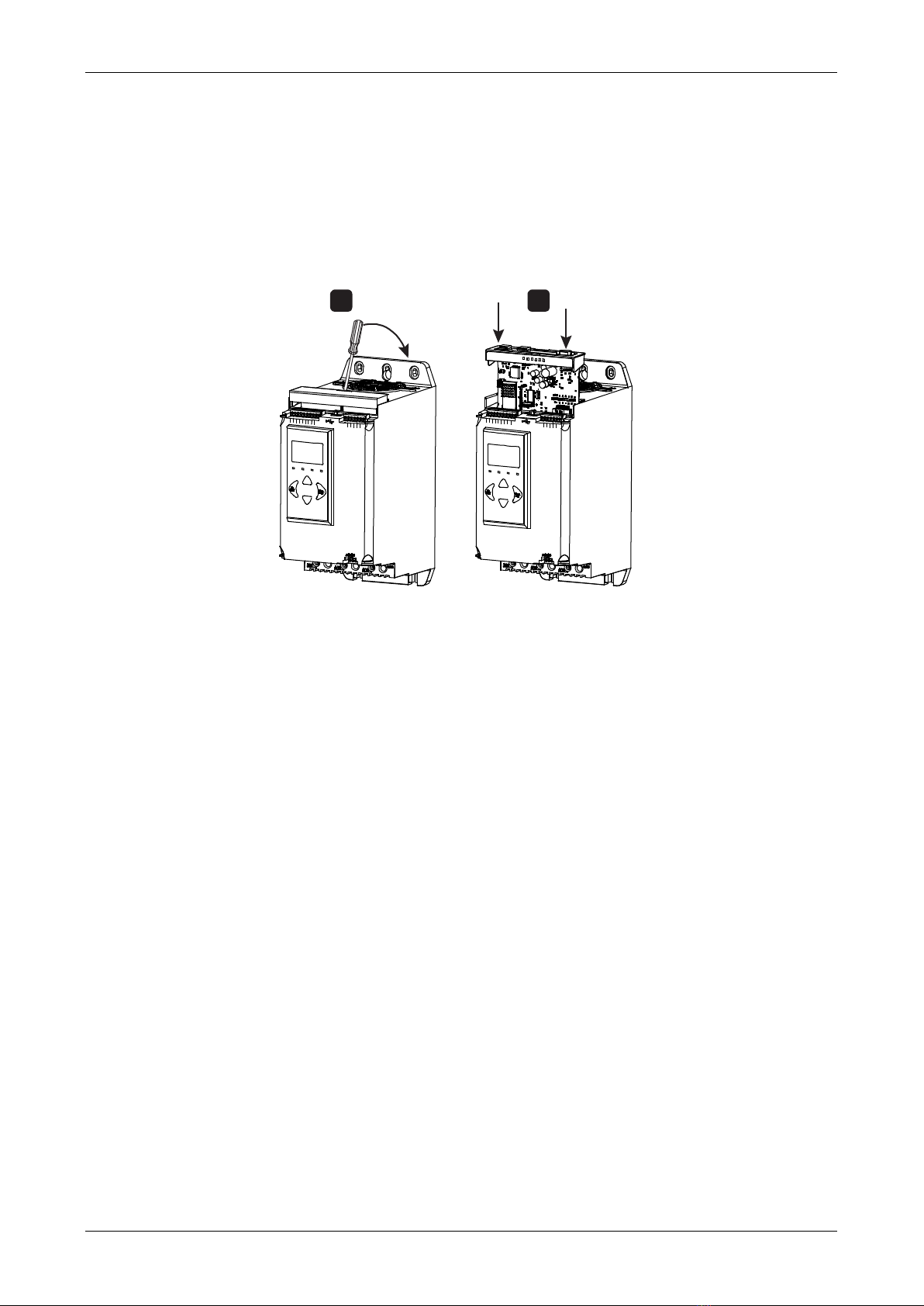
2.1 Installing the expansion card
1. Push a small flat-bladed screwdriver into the slot in the centre of the expansion
port cover, and ease the cover away from the starter.
2. Line up the card with the expansion port. Gently push the card along the guide
rails until it clicks into the starter.
B4 B5 10
1112 13 14 15 21 22
33 34 41 42 44 53 54
B4 B5 10
1
1 12 13 14 15 21 22
33 34 41 42 44 53 54
1 2
17049.A
2.2 Network connection
Ethernet ports
The device has two Ethernet ports. If only one connection is required, either port can
be used.
Cables
Use Category 5, 5e, 6 or 6e cable to connect to the device.
EMC precautions
To minimise electromagnetic interference, Ethernet cables should be separated from
motor and mains cables by 200 mm.
If the Ethernet cable must cross motor or mains cables, the crossing should be at an
angle of 90°.
2.3 Network establishment
The controller must establish communications directly with each device before the
device can participate in the network.
2.4 Addressing
Each device in a network is addressed using a MAC address and a device name. The
MAC address is fixed within the device and is printed on a label on the front of the
device.

INSTRUCTIONS
6Profinet Card (710-16502-00C)
3. Device configuration
3.1 Configure the device name
Use the Ethernet Device Configuration Tool to configure the device. The Ethernet
Device Configuration Tool is available from your local supplier.
To identify the device using the Ethernet Device Configuration Tool:
1. Start the Ethernet Device Configuration Tool.
2. Click on Search Devices. The software will search for connected devices.
3. To configure a device name, click Configure then select Device Name.
NOTE
The Error LED is on if the device is not configured. If the device is configured
but is not passing I/O data, the Error LED will flash. The Error LED will be
active during the configuration process.
NOTE
If your PC has a firewall enabled, you must add the tool to the list of authorised
programs.

INSTRUCTIONS
Profinet Card (710-16502-00C) 7
3.2 Enabling network control
The soft starter will only accept commands from the Profinet Card if parameter 1A
Command Source
is set to 'Network'.
NOTE
If the reset input is active, the starter will not operate. If a reset switch is not
required, use parameter 7I to set the reset input to normally open or fit a link
across terminals 10, 11 on the soft starter.
3.3 On-board web server
Settings in the Profinet Card can be configured via the card's web server.
Connect to the device
To configure settings using the on-board web server, the card must be installed in a
soft starter, control power must be available, and the card and computer must both be
connected to the Ethernet network.
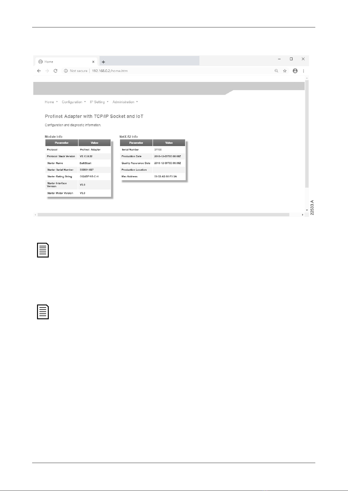
The computer must use a fixed IP address (not DHCP) and the same subnet mask as
the card. The default IP address for the card is 192.168.0.2. The default subnet mask is
255.255.255.0.
INSTRUCTIONS
8Profinet Card (710-16502-00C)
Once connected, the web server reports basic information about the card and the soft
starter.
Manage users and passwords
NOTE
For security reasons, we recommend that you define a custom administrator
ID and password.
The default username and password are:
username: admin
password: 1978
NOTE
Version 2.x of the Profinet Card does not support custom users.
The Profinet Card supports multiple users and levels of privilege.
•Users can view the home screen and IP address settings
•Supervisors can view the home screen and IP settings and can change
configuration settings
•Administrators can view the home screen, change configuration settings and add or
delete users
To add a new user:
1. Connect to the web server then click Administration.
2. Click Create new user.
3. Enter the new username and password then click Create an account.
4. Set privileges (user, supervisor, administrator) as appropriate.
5. Click Save changes.

INSTRUCTIONS
Profinet Card (710-16502-00C) 9
To delete a user:
1. Connect to the web server then click Administration.
2. Click the required entry in the user list then click Delete user. Click Delete again to
confirm the action.
Configure IoT settings
The Profinet Card supports soft starter status monitoring over IoT. The card cannot
control or program the soft starter.
NOTE
Version 2.x of the Profinet Card does not support IoT operation.
•Configure MQTT settings
1. Connect to the web server then click Configuration > MQTT Client.
2. Tick the Enable checkbox to enable MQTT client operation. The MQTT client is
enabled by default.
3. Click Connection then configure the settings as required.
4. Use Connection > Actions to select which information the card will publish.
5. Click Submit to save all settings in the card.

INSTRUCTIONS
10 Profinet Card (710-16502-00C)
•Configure OPC UA settings
1. Connect to the web server then click Configuration > OPC UA Server.
2. Tick the Enable checkbox to enable OPC UA client operation. The OPC UA client is
enabled by default.
3. Click Server Configuration then configure the settings as required.
4. Use Actions to select the actions for different object instances.
5. Click Submit to save all settings in the card.

INSTRUCTIONS
Profinet Card (710-16502-00C) 11
4. Master configuration
Import the latest GSDML file into your Master configuration tool. This file is available
from your supplier.
If your Master uses on-screen icons, two graphic bitmap files are available from the
website. SSPM_N.bmp indicates normal mode. SSPM_D.bmp indicates diagnostic
mode.
5. Ground fault protection
NOTE
Ground fault protection is only available on ground fault enabled cards,
with soft starters running a compatible version of software. Contact your
supplier for assistance.
5.1 Overview
Ground fault protection
The Profinet Card can detect ground current and trip before the equipment is
damaged.
Ground fault protection requires a 1000:1 or 2000:1 5 VA current transformer (not
supplied). The soft starter can be configured to trip at 1 A~50 A. If ground fault current
rises above 50 A, the soft starter will trip immediately.
5.2 Connect the CT to the ground fault inputs
To use ground fault protection, a common mode current transformer (CT) must be
installed around all three phases. Use a 1000:1 or 2000:1 CT with rating of 5 VA and set
parameter 40E
Ground Fault CT Ratio
to match. Connect the CT to the ground fault
terminals (G1, G2, G3).
For maximum protection, the CT should be installed on the input side of the soft
starter.
5.3 Configure ground fault protection settings
Ground fault protection settings must be set in the soft starter.
Parameter
Parameter name
Description
40A
Ground fault trip
level
Sets the trip point for ground fault current
protection.
40B
Ground fault trip
delay
Slows the soft starter’s response to ground fault,
avoiding trips due to momentary fluctuations.
40C
Ground fault trip
active
Selects when a ground fault trip can occur.

INSTRUCTIONS
12 Profinet Card (710-16502-00C)
Parameter
Parameter name
Description
40D
Ground fault action
Selects the soft starter’s response to the
protection event.
40E
Ground fault CT ratio
Set to match the ratio of the ground current
measuring CT.
6. Operation
The device has been designed for use in a system complying with the Profinet
standard. For successful operation, the controller must also support all functions
and interfaces described in this document.
6.1 Device classification
The Profinet Card is a Profinet IO-Device and must be managed by an IO-Controller
over Ethernet.
6.2 Ensuring safe and successful control
Data written to the device will remain in its registers until the data is overwritten or
the device is reinitialised.
If the soft starter may be controlled via Command Override (parameter 7A) or may be
disabled via the reset input (terminals 10, 11) fieldbus commands should be cleared
from the registers. If a command is not cleared, it will be re-sent to the starter once
fieldbus control resumes.
6.3 Feedback LEDs
Port 1 Port 2 Keypad
LINK 2
TX/RX2
LINK 1
TX/RX1
ERROR
STATUS
17821.A
LED name
LED state
Description
Power
Off
Device is not powered up.
On
Device is receiving power.
Error Off No error.
Flashing
Connection not established.
On No physical link or slow physical link.
No configuration.
Status
Off
No error.
Flashing DCP signal service initiated via the bus.
Link x
Off
No network connection.
On Connected to a network.
TX/RX x
Flashing
Transmitting or receiving data.

INSTRUCTIONS
Profinet Card (710-16502-00C) 13
7. Packet structures
NOTE
The available features and parameter details may vary according to the model
and software version of the starter. Refer to the soft starter user manual for
details of parameters and supported features.
7.1 Control commands (controller to device)
Use output bytes 0-1 to send a control command to the soft starter.
Byte
Bits
Details
0
0 to 1
Reserved
2 to 3 0 = Use soft starter remote input to select motor set
1 = Use primary motor set when starting
2 = Use secondary motor set when starting
3 =
Reserved
4
0 = stop action will be as selected in the soft starter
1 = stop action will be a coast to stop
5 to 7
Reserved
1
0
0 = Stop
1 = Start
1 to 2
Reserved
3 1 = Reset
4 to 7
Reserved
2 to 5
Parameter management (refer to
Parameter management
on
page 17)
7.2 Status information (device to controller)
Starter status information is always available when the device is active.
Bytes 0-1: Control status
Bits
Details
0 to 5 Current (% motor FLC)
6
Command source
0 = Network, Timer
1 = Remote Keypad, Digital Input, Clock
7
1 = Ramping (starting or stopping)
8 1 = Ready
9
1 = Starting, running or stopping
10 1 = Tripped
11
1 = Warning
12 to 15
Reserved

INSTRUCTIONS
14 Profinet Card (710-16502-00C)
Bytes 2-3: Starter state
Bits
Details
0 to 3 The decimal value of bits 0~3 indicates the starter's state:
0 = Communication error between device and soft starter
1 = Ready
2 = Starting
3 = Running
4 = Stopping
5 = Not ready (restart delay, restart temperature check, run simulation,
reset input is open)
6 = Tripped
7 = Menu open (cannot start)
8 = Jog forward
9 = Jog reverse
4
0 = Negative phase sequence
1 = Positive phase sequence
5
1 = Current exceeds FLC
6 0 = Uninitialised
1 = Initialised
7
1 = Communication error between device and soft starter
8 to 15
Reserved
Bytes 4-5: Trip code
Bits
Details
0 to 15
Refer to Trip codes on page 18
Bytes 6-7: Motor current
Bits
Details
0 to 15
Average rms current across all three phases
Bytes 8-9: Motor temperature
Bits
Details
0 to 15
Motor thermal model (%)

INSTRUCTIONS
Profinet Card (710-16502-00C) 15
Bytes 10-63: Extended information
Bytes 10~63 report information from the soft starter's internal registers.
Byte
Description
Bits
Details
10-11 Version 0 to 8
Reserved
9 to 15
Product type code:
12 = EMX4e
13 = EMX4i
12-13
Model number
0 to 7
Reserved
8 to 15 Soft starter model ID
14-15
Reserved
16-17
Reserved
18-19 Starter state 0 to 4 0 =
Reserved
1 = Ready
2 = Starting
3 = Running
4 = Stopping
5 = Not ready (restart delay, restart
temperature check, run simulation, reset
input is open)
6 = Tripped
7 = Programming mode
8 = Jog forward
9 = Jog reverse
5
1 = Warning
6 0 = Uninitialised
1 = Initialised
7
Command source
0 = Network, Timer
1 = Remote Keypad, Digital Input, Clock
8
Reserved
9 0 = Negative phase sequence
1 = Positive phase sequence
10 to 15
Reserved
20-21
Current
0 to 13
Average rms current across all three phases
14 to 15
Reserved
22-23
Current
0 to 9
Current (% motor FLC)
10 to 15
Reserved
24-25 Motor temperature 0 to 7 Motor thermal model (%)
8 to 15
Reserved

INSTRUCTIONS
16 Profinet Card (710-16502-00C)
Byte
Description
Bits
Details
26-27 Power
0 to 11 Power
12 to 13
Power scale
0 = Multiply power by 10 to get W
1 = Multiply power by 100 to get W
2 = Power (kW)
3 = Multiply power by 10 to get kW
14 to 15
Reserved
28-29
% Power factor
0 to 7
100% = power factor of 1
8 to 15
Reserved
30-31
Voltage
0 to 13
Average rms voltage across all three phases
14 to 15
Reserved
32-33
Current
0 to 13
Phase 1 current (rms)
14 to 15
Reserved
34-35
Current
0 to 13
Phase 2 current (rms)
14 to 15
Reserved
36-37 Current 0 to 13 Phase 3 current (rms)
14 to 15
Reserved
38-39 Voltage 0 to 13 Phase 1 voltage (rms)
14 to 15
Reserved
40-41
Voltage
0 to 13
Phase 2 voltage (rms)
14 to 15
Reserved
42-43
Voltage
0 to 13
Phase 3 voltage (rms)
14 to 15
Reserved
44-45
Parameter list
0 to 7
Parameter list minor revision
version number 8 to 15 Parameter list major version
46-47
Digital input state
For all inputs, 0 = open, 1 = closed (shorted)
0
Start/Stop
1
Reserved
2
Reset (Refer to note)
3 Input A
4
Input B
5 to 15
Reserved
48-49
Trip code
0 to 15
Refer to Trip codes on page 18
50-51
Reserved
52-53
Frequency
Frequency (Hz)
54-55
Ground current
Ground current (A)
56-59
Reserved
60-63
Parameter
management
Refer to Parameter management on page 17

INSTRUCTIONS
Profinet Card (710-16502-00C) 17
NOTE
The reset input is normally closed by default. If parameter 7I
Reset/Enable
Logic
is set to normally open, the reported state will be inverted (0 = closed, 1 =
open).
NOTE
For models EMX4x-
0064B and smaller, current reported via communications is
10 times greater than the actual value (displayed on the keypad).
NOTE
Frequency reported via communications is 10 times greater than the actual
value.
7.3 Parameter management
The Profinet Card can read parameter values from and write parameter values to the
soft starter. The card handles one parameter at a time.
The device references parameters according to their position in the starter's
parameter list.
NOTE
Parameter lists vary according to the model and version of soft starter. Refer
to the relevant soft starter literature for a complete parameter list.
CAUTION
Changing the values of the Advanced parameters (parameter group 20) may
cause unpredictable behaviour in the soft starter. Consult your local supplier
before adjusting the Advanced parameters.
Output
Use output bytes 2-5 to read or write a parameter to the soft starter.
Controller > device output bytes are structured as follows.
Byte
Bits
Details
2
0 to 7
Parameter number to read/write
3
0
Reserved
1 1 = Read parameter
2
1 = Write parameter
3 to 7
Reserved
4
0 to 7
Low byte parameter value to write to soft starter/ zero data
values for read
5
0 to 7
High byte parameter value to write to soft starter/ zero data
values for read

INSTRUCTIONS
18 Profinet Card (710-16502-00C)
Input
Parameter data from the starter is reported in input bytes 60-63.
Device > controller input bytes are structured as follows.
Byte
Bits
Details
60
0 to 7
Echo parameter number
61 0 1 = Invalid parameter number
1
1 = Invalid parameter value
2 to 7
Reserved
62
0 to 7
Low byte parameter value read from soft starter
63
0 to 7
High byte parameter value read from soft starter
7.4 Trip codes
Trip code
Description
255
No trip
1
Excess start time
2
Motor overload
3 Motor thermistor
4 Current imbalance
5
Frequency
6
Phase sequence
7
Overcurrent
8
Power loss
9 Undercurrent
10
Heatsink overtemperature
11
Motor connection
12
Input A trip
13
FLC too high
14
Unsupported option (function not available in inside delta)
15 Communications card fault
16 Network communication
18
Overvoltage
19
Undervoltage
23
Parameter out of range
24 Input B trip
26 L1 phase loss
27
L2 phase loss
28
L3 phase loss
29
L1-T1 shorted
30
L2-T2 shorted

INSTRUCTIONS
Profinet Card (710-16502-00C) 19
Trip code
Description
31
L3-T3 shorted
33 Time-overcurrent (Bypass overload)
34
SCR overtemperature
35
Battery/clock
36
Thermistor circuit
47
Overpower
48 Underpower
56 Keypad disconnected
57
Zero Speed Detect
58
SCR Itsm
59
Instantaneous overcurrent
60
Rating Capacity
70 Current Read Err L1
71
Current Read Err L2
72
Current Read Err L3
74
Motor Connection T1
75
Motor Connection T2
76
Motor Connection T3
77 Firing Fail P1
78
Firing Fail P2
79
Firing Fail P3
80
VZC Fail P1
81
VZC Fail P2
82 VZC Fail P3
83 Low Control Volts
84~96
Internal fault x. Contact your local supplier with the fault code (X).
7.5 Examples
Control commands (controller to device)
Start the motor using parameter set 1
Byte 0
Byte 1
Byte 2
Byte 3
Byte 4
Byte 5
Byte 6
Byte 7
4
1
Start the motor, select via remote input
Byte 0 Byte 1 Byte 2 Byte 3 Byte 4 Byte 5 Byte 6 Byte 7
0
1
Stop the motor using the programmed soft stop for motor set 2
Byte 0 Byte 1 Byte 2 Byte 3 Byte 4 Byte 5 Byte 6 Byte 7
8
0

INSTRUCTIONS
20 Profinet Card (710-16502-00C)
Quick stop the motor
Byte 0 Byte 1 Byte 2 Byte 3 Byte 4 Byte 5 Byte 6 Byte 7
16
0
Reset a trip
Byte 0 Byte 1 Byte 2 Byte 3 Byte 4 Byte 5 Byte 6 Byte 7
≤ 28
8
Status information (device to controller)
Read control status - Ready
Byte 0 Byte 1 Byte 2 Byte 3 Byte 4 Byte 5 Byte 6 Byte 7
0
1
Read control status - Running
Byte 0 Byte 1 Byte 2 Byte 3 Byte 4 Byte 5 Byte 6 Byte 7
3
0
Read control status - Tripped, trip code 4 (Current imbalance)
Byte 0 Byte 1 Byte 2 Byte 3 Byte 4 Byte 5 Byte 6 Byte 7
6
0
4
0
Parameter management
Write parameter to starter: parameter number 2, 1B
Motor Full Load Current
= 55
Byte 0
Byte 1
Byte 2
Byte 3
Byte 4
Byte 5
Byte 6
Byte 7
2
4
55
0
Parameter write response
Byte 56
Byte 57
Byte 58
Byte 59
Byte 60
Byte 61
Byte 62
Byte 63
2
0
55
0
EMX4e: Read parameter number 12, 2I
Stop Mode
Byte 0
Byte 1
Byte 2
Byte 3
Byte 4
Byte 5
Byte 6
Byte 7
12
2
0
0
Parameter read response: parameter 2I
Stop Mode
= 1 (TVR Soft Stop)
Byte 56
Byte 57
Byte 58
Byte 59
Byte 60
Byte 61
Byte 62
Byte 63
12
0
1
0
Table of contents
Other AuCom Industrial Equipment manuals

Popular Industrial Equipment manuals by other brands


ABB
ABB HT842454 Operation manual

HMS
HMS Anybus Wireless Bolt SP2554 Series Startup guide

Wilo
Wilo Wilo-Helix V FIRST V 2.0-VE 2 Installation and operating instructions

Graco
Graco EcoQuip 300 Operation, repair, and parts

MICRO-EPSILON
MICRO-EPSILON thicknessSENSOR 10/200 operating instructions

ABB
ABB HT567437 Operation manual


