AuCom MVS Series User manual
GUIDE
MVS SERIES SOFT STARTERS
PRODUCT
http://www.kontrolkalemi.com/forum/

CONTENTS
MVS SERIES 1 710-03261-00A
Section 1 Caution Statements
Section 2 General Description
2.1 Overview.......................................................................................................... 3
2.2 Feature List...................................................................................................... 3
2.3 Type Codes ..................................................................................................... 4
Section 3 Specifications
3.1 Current Ratings ............................................................................................... 5
3.2 Dimensions and Weights................................................................................. 6
3.3 General Technical Data................................................................................... 7
Section 4 Installation
4.1 Mounting Instructions – Power Assembly ....................................................... 9
4.2 Mounting Instructions – Controller ................................................................ 10
4.3 Power Terminations ...................................................................................... 11
4.4 Control Terminations ..................................................................................... 12
4.5 Electrical Schematic ...................................................................................... 12
4.6 Internal Wiring ............................................................................................... 13
Section 5 System Design
5.1 Overview........................................................................................................ 14
5.2 Main Contactor .............................................................................................. 14
5.3 Bypass Contactor .......................................................................................... 14
5.4 Main Isolator / Earth Switch .......................................................................... 16
5.5 "R Rated" Protection Fuses........................................................................... 16
5.6 Power Factor Correction Capacitor Contactor .............................................. 16
5.7 Line Inductors................................................................................................ 16
5.8 Transient / Overvoltage Protection................................................................ 16
5.9 Medium Voltage Control Supply Transformer ............................................... 16
Section 6 Application Examples
6.1 Installation into a Panel ................................................................................. 18
http://www.kontrolkalemi.com/forum/

CAUTION STATEMENTS
710-03261-00A 2 MVS SERIES
Section 1 Caution Statements
This symbol is used throughout this manual to draw attention to topics
of special importance to the installation and operation of the MVS soft
starter.
Caution Statements cannot cover every potential cause of equipment damage but
can highlight common causes of damage. It is therefore the installer’s
responsibility to adhere to all instructions in this manual, to follow good electrical
practice and to seek advice before operating this equipment in a manner other than
as detailed in this manual.
•Ensure that the MVS is completely isolated from the power supply before
attempting any work on the unit.
•Entry of metal swarf into the cabinet can cause equipment failure.
•Do not apply voltage to the control input terminals. These are active
24 VDC inputs and must be controlled with potential free circuits.
•Ensure contacts/switches operating the control inputs are suitable for low
voltage, low current switching (ie gold flash or similar).
•Ensure cables to the control inputs are segregated from AC power and
control wiring.
•Some electronic contactor coils are not suitable for direct switching with
PCB mount relays. Consult the contactor manufacturer/supplier to see if
this is advisable.
•Do not connect power factor correction capacitors to the output of the
MVS. If static power factor correction is employed, it must be connected to
the supply side of the MVS.
The examples and diagrams in this manual are included solely for illustrative
purposes. Users are cautioned that the information contained in this manual is
subject to change at any time and without prior notice. In no event will
responsibility or liability be accepted for direct or indirect or consequential damages
resulting from the use or application of this equipment.
WARNING – ELECTRICAL SHOCK HAZARD
The MVS contains dangerous voltages when connected to line
voltage. Only a competent electrician should carry out the electrical
installation. Improper installation of the motor or the MVS may cause
equipment failure, serious injury or death. Follow this manual, the
National Electrical Code (NEC®) and local safety codes.
GROUNDING AND BRANCH CIRCUIT PROTECTION
It is the responsibility of the user or person installing the MVS to
provide proper grounding and branch circuit protection according to
the National Electrical Code (NEC®) and local safety codes.
SHORT CIRCUIT
The MVS is not short circuit proof. Therefore, after severe overload
or short circuit, the operation of the starter should be fully tested.
http://www.kontrolkalemi.com/forum/

GENERAL DESCRIPTION
MVS SERIES 3 710-03261-00A
Section 2 General Description
2.1 Overview
The MVS Series provides compact and robust soft start solutions for control of
medium voltage motors. MVS Series soft starters provide a complete range of
motor and system protection features and have been designed for reliable
performance in the most demanding installation situations.
The MVS soft starter comprises two elements:
•a power assembly, which varies between different models (depending on
mains voltage and current rating)
•a controller module, which is common to all models
The power assembly and controller module are supplied as a pair and share the
same serial number. Care should be taken during installation to ensure the correct
controller and power assembly are used together.
2.2 Feature List
Starting
•Constant Current
•Current Ramp
•Torque Control
Stopping
•Soft Stop
Protection
•Under/Overvoltage
•Supply Frequency
•Phase Sequence
•Shorted SCR
•Motor Overload (Thermal Model)
•Electronic Shearpin
•Ground Fault
•Undercurrent
•Phase Imbalance
•Motor Thermistor
•Excess Start Time
•Power Circuit
•Auxiliary Trip
Interface
•Remote Control Inputs
(3 x fixed, 2 x programmable)
•Relay Outputs
(3 fixed, 3 x programmable)
•Analogue Output (1 x programmable)
•Serial Output (1 x RS485)
Human Interface
•Multi-Language Display
•Starter Status LEDs
•Event Log (99 positions, date and
time stamped)
•Trip Log (8 positions, date and time
stamped)
•Counters (starts, hours-run, kWh)
•Metering (current, voltage, power
factor, kWh)
•User Programmable Metering
Screen
•Multi-Level Password Protection
Power Connection
•80 A to 321 A, nominal
•2300 VAC to 11000 VAC
Accessories (optional)
•RTD Interface
•Modbus RTU Interface
•Profibus Interface
•DeviceNet Interface
•Synchronous Motor Control
•PC Software
•Remote Operator
•Overvoltage Protection
•MV Control Supply Transformer
http://www.kontrolkalemi.com/forum/

GENERAL DESCRIPTION
710-03261-00A 4 MVS SERIES
2.3 Type Codes
Supply Voltage
V02 = 2300 VAC 50 / 60 Hz
V03 = 3300 VAC 50 / 60 Hz
V04 = 4160 VAC 50 / 60 Hz
V06 = 6600 VAC 50 / 60 Hz
V07 = 7200 VAC 50 / 60 Hz
V11 = 11000 VAC 50 / 60 Hz
Control Supply Voltage
C12 = 110 VAC & 230 VAC
MVS --
Current Rating
0080 = 80 A @ AC53b 4-20 : 1780
0159 = 159 A @ AC53b 4-20 : 1780
0230 = 230 A @ AC53b 4-20 : 1780
0321 = 321 A @ AC53b 4-20 : 1780
http://www.kontrolkalemi.com/forum/

SPECIFICATIONS
MVS SERIES 5 710-03261-00A
Section 3 Specifications
3.1 Current Ratings
Two starts per hour
3.5-15:1785 4.0-20:1780 4.0-30:1770 5.0-30:1770 5.0-60:1740
40 °C 50 °C 40 °C 50 °C 40 °C 50 °C 40 °C 50 °C 40 °C 50 °C
MVS-0080-xxx 96 91 80 74 72 66 59 55 46 42
MVS-0159-xxx 190 177 159 147 143 132 117 109 91 84
MVS-0230-xxx 282 261 230 213 201 185 165 152 121 111
MVS-0321-xxx 393 363 321 296 279 257 229 211 168 154
Three starts per hour
4.0-20:1180 4.0-30:1170 5.0-30:1170 5.0-60:1140
40 °C 50 °C 40 °C 50 °C 40 °C 50 °C 40 °C 50 °C
MVS-0080-xxx 73 68 65 60 53 49 40 37
MVS-0159-xxx 146 135 129 119 106 98 79 73
MVS-0230-xxx 207 190 175 162 144 132 101 93
MVS-0321-xxx 288 265 244 225 200 184 141 129
Four starts per hour
4.0-20:880 4.0-30:870 5.0-30:870 5.0-60:840
40 °C 50 °C 40 °C 50 °C 40 °C 50 °C 40 °C 50 °C
MVS-0080-xxx 68 63 59 54 48 45 35 33
MVS-0159-xxx 136 125 117 108 96 89 70 65
MVS-0230-xxx 188 173 157 144 129 118 88 81
MVS-0321-xxx 262 241 218 200 179 164 122 112
AC53b Utilisation Category Format
80 A: AC-53b 4-20 : 1780
Off Time (seconds)
Start Time (seconds)
Start Current (multiple of FLC)
Starter Current Rating (amperes)
Starter Current Rating: The full load current rating of the soft starter given the
parameters detailed in the remaining sections of the utilisation code.
Start Current: The maximum available start current given the parameters detailed
in the remaining sections of the utilisation code.
Start Time: The maximum available start time given the parameters detailed in the
remaining sections of the utilisation code.
Off Time: The minimum allowable time between the end of one start and the
beginning of the next start given the parameters detailed in the remaining sections
of the utilisation code.
Contact your local supplier for ratings under operating conditions not covered by
the above charts.
http://www.kontrolkalemi.com/forum/

SPECIFICATIONS
710-03261-00A 6 MVS SERIES
3.2 Dimensions and Weights
Power Assembly
Aa
b
B
c
C
d
e
Front View Side View
Extended
A
mm
(inch)
B
mm
(inch)
C
mm
(inch)
a
mm
(inch)
b
mm
(inch)
c
mm
(inch)
d
mm
(inch)
e
mm
(inch)
Weight
kg (lb)
MVS-
xxxx-V02
MVS-
xxxx-V03
MVS-
xxxx-V04
772
(30.39)
669
(26.34)
667
(26.26)
750
(29.53)
658
(25.91)
650
(25.59)
1302
(51.26)
531
(20.91)
165
(363.76)
MVS-
xxxx-V06
MVS-
xxxx-V07
832
(32.76)
875
(34.45)
817
(32.17)
810
(31.89)
864
(34.02)
800
(31.50)
1559
(61.38)
551
(21.69)
217
(478.40)
Please contact your local supplier for dimensions for MVS-xxxx-V11.
Controller
The MVS controller is suitable for use with all models in the MVS Series.
340.0
(13.39)
54.0
(2.13)
mm (inch)
Weight: 2.1 kg (4.63 lb)
http://www.kontrolkalemi.com/forum/

SPECIFICATIONS
MVS SERIES 7 710-03261-00A
3.3 General Technical Data
Supply
Mains Supply Voltage
MVSxxxx-V02-xxx ........................................................ 3 x 2300 VAC (± 10%)
MVSxxxx-V03-xxx ........................................................ 3 x 3300 VAC (± 10%)
MVSxxxx-V04-xxx ........................................................ 3 x 4160 VAC (± 10%)
MVSxxxx-V06-xxx ........................................................ 3 x 6600 VAC (± 10%)
MVSxxxx-V07-xxx ...................................................... 3 x 7200 VAC (± 10%)
MVSxxxx-V11-xxx ..................................................... 3 x 11000 VAC (± 10%)
Control Supply Voltage
MVSxxx-xxx-C12 ................................ 110 VAC to 130 VAC (+ 10% / - 15%)
or 220 VAC to 240 VAC (+ 10% / - 15%)
Supply Frequency .......................................................................... 45 Hz to 66 Hz
Rated Insulation Voltage
MVSxxxx-V02-xxx ........................................................................... 4200 VAC
MVSxxxx-V03-xxx ........................................................................... 4200 VAC
MVSxxxx-V04-xxx ........................................................................... 4200 VAC
MVSxxxx-V06-xxx ........................................................................... 6600 VAC
MVSxxxx-V07-xxx ........................................................................... 7200 VAC
MVSxxxx-V11-xxx ......................................................................... 11000 VAC
Rated Impulse Withstand Voltage (BIL)
MVSxxxx-V02-xxx .......................... 23300 VAC Cat III (1.2/ 50 µs at 2000 m)
MVSxxxx-V03-xxx .......................... 23300 VAC Cat III (1.2/ 50 µs at 2000 m)
MVSxxxx-V04-xxx .......................... 23300 VAC Cat III (1.2/ 50 µs at 2000 m)
MVSxxxx-V06-xxx .......................... 36700 VAC Cat III (1.2/ 50 µs at 2000 m)
MVSxxxx-V07-xxx .......................... 40000 VAC Cat III (1.2/ 50 µs at 2000 m)
MVSxxxx-V11-xxx ................................ xx VAC Cat III (1.2/ 50 µs at 2000 m)
Form Designation ......................... Bypassed semiconductor motor starter form 1
Control Inputs
Start (Terminals C23, C24) ..................................... Active 24 VDC, 8 mA approx
Stop (Terminals C31, C32) ..................................... Active 24 VDC, 8 mA approx
Reset (Terminals C41, C42) ................................... Active 24 VDC, 8 mA approx
Programmable Input A (Terminals C53, C54) ........ Active 24 VDC, 8 mA approx
Programmable Input B (Terminals C63, C64) ........ Active 24 VDC, 8 mA approx
Motor Thermistor (Terminals B4, B5)
Outputs
Relay Outputs ............................................................. 10 A @ 250 VAC / 360 VA
10 A @ 30 VDC resistive
Main Contactor (Terminals 13, 14) ................................................ Normally Open
Bypass Contactor (Terminals 23, 24) ............................................. Normally Open
Run Output / PFC (Terminals 31, 32, 34) ............................................Changeover
Programmable Relay Output A (Terminals 43, 44) ....................... Normally Open
Programmable Relay Output B (Terminals 51, 52, 54) ...................... Changeover
Programmable Relay Output C (Terminals 61, 62, 64) ...................... Changeover
Analogue Output (Terminals B10, B11) .................................................. 4-20 mA
http://www.kontrolkalemi.com/forum/

SPECIFICATIONS
710-03261-00A 8 MVS SERIES
Environmental
Degree of Protection
Power Assembly ...................................................................................... IP00
Controller ............................................................................... IP54 / NEMA 12
Motor Controller Panel (optional) ........................... designed to IP54 / NEMA 12
Operating Temperature ............................................................. - 10 ˚C to + 60 ˚C
Storage Temperature ................................................................ - 25 ˚C to + 55 ˚C
Humidity ................................................................ 5% to 95% Relative Humidity
Pollution Degree ....................................................................... Pollution Degree 3
Vibration ..................................................................IEC 60068 Test Fc Sinusoidal
4 Hz to 13.2 Hz: ± 1 mm displacement
13.2 Hz to 200 Hz: ± 0.7 g
EMC Emission
Equipment Class (EMC) ............................................................................. Class A
Conducted Radio Frequency Emission ..... 10 kHz to 150 kHz: < 120 - 69 dB µV
0.15 MHz to 0.5 MHz: < 79 dB µV
0.5 MHz to 30 MHz: < 73 dB µV
Radiated Radio Frequency Emission .... 0.15 MHz to 30 MHz: < 80-50 dB µV/m
30 MHz to 100 MHz: < 60-54 dB µV/m
100 MHz to 2000 MHz: < 54 dB µV/m
This product has been designed for Class A equipment. Use of the product in
domestic environments may cause radio interference, in which case the user may
be required to employ additional mitigation methods.
EMC Immunity
Electrostatic Discharge ..................... 6 kV contact discharge, 8 kV air discharge
Radio Frequency Electromagnetic Field ............... 80 MHz to 1000 MHz: 10 V/m
Fast Transients 5/50 ns (main and control circuits) .................................................
2 kV line to earth, 1 kV line to line
Surges 1.2/50 µs (main and control circuits) ....2 kV line to earth, 1 kV line to line
Voltage dip and short time interruption ............ 5000 ms (at 0% nominal voltage)
(safe shutdown)
Short Circuit
Rated short-circuit current
MVSxxxx-V02-xxx .................................................................................. 68 kA
MVSxxxx-V03-xxx .................................................................................... 68 kA
MVSxxxx-V04-xxx .................................................................................. 68 kA
MVSxxxx-V06-xxx .................................................................................. XX kA
MVSxxxx-V07-xxx .................................................................................. XX kA
MVSxxxx-V11-xxx .................................................................................. XX kA
Heat Dissipation (Steady State)
Power Assembly (SCRs bypassed) ................................................. 20 W approx
Controller ........................................................................................... 10 W approx
Standards Approvals
C9.......................................................................................... EMC requirements
UL / C-UL ..................................................................................... UL 508, UL 347
CE ........................................................................................... EMC EU Directive
Marine ...................................................................................................... pending
http://www.kontrolkalemi.com/forum/

INSTALLATION
MVS SERIES 9 710-03261-00A
Section 4 Installation
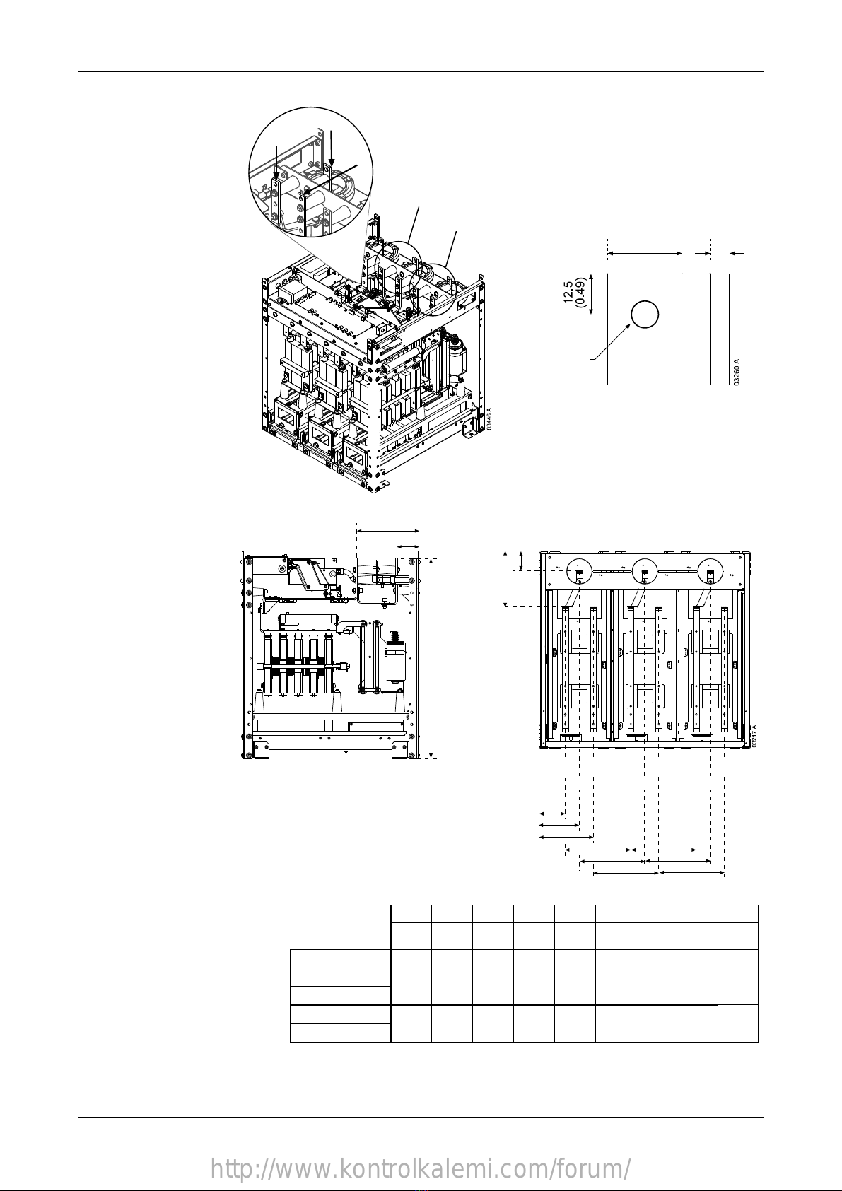
4.1 Mounting Instructions – Power Assembly
All models in the MVS Series have an IP00 rating and must be installed inside an
enclosure. The power assembly should be installed with 100 mm clearance above
for isolation; no clearance is required below or at the sides.
min 100 mm (3.93 inch)
The MVS power assembly is mounted in place using four M12 bolts. One bolt is
required through each corner at the base of the unit, tightened to a torque of
40 Nm.
Front of Unit
A
To suit M12 mounting bolt
Horizontal Cross-section
A
mm (inch)
B
mm (inch)
C
mm (inch)
MVS-xxxx-V02
MVS-xxxx-V03
MVS-xxxx-V04
636
(25.04)
513
(20.20)
68.5
(2.70)
MVS-xxxx-V06
MVS-xxxx-V07
842
(33.15)
663
(26.10)
68.5
(2.70)
http://www.kontrolkalemi.com/forum/
INSTALLATION
710-03261-00A 10 MVS SERIES
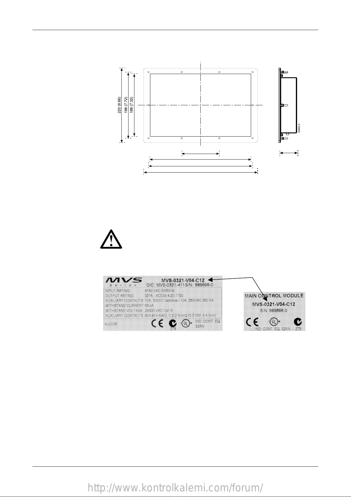
4.2 Mounting Instructions – Controller
The MVS controller can be secured in place with ten M4 nuts, affixed to the bolts
on the back of the controller.
112 (4.41)
300 (11.81)
310 (12.20)
340 (13.39)
54.0 (2.13)
To mount the controller, make a 186 mm x 300 mm cutout at the desired mounting
location. Ensure adequate clearance (54 mm) is available behind the mounting
location.
Drill 5 mm holes to accommodate the bolts on the controller. Fit the controller
through the cutout and tighten the nuts onto the bolts.
NOTE
Before installation, always ensure that you are using the correct controller
for the starter. This can be checked by comparing the serial number on
the back of the controller with the serial number on the front of the power
assembly.
Serial number
http://www.kontrolkalemi.com/forum/
INSTALLATION
MVS SERIES 11 710-03261-00A
4.3 Power Terminations
T3, T3B, L3
T2, T2B, L2
L1
T1
T1B
6
(0.24)
25
(0.98)
13
(0.51)
Rear of Unit
ii
a
b
d
e
f
g
h
g
h
T1B T2B T3B
L3L2L1 T3T2T1
a
b
c
abcde f gh i
mm
(inch)
mm
(inch)
mm
(inch)
mm
(inch)
mm
(inch)
mm
(inch)
mm
(inch)
mm
(inch)
mm
(inch)
MVS-xxxx-V02
MVS-xxxx-V03
MVS-xxxx-V04
228
(8.98)
79
(3.11)
744
(29.29)
79
(3.11)
129
(5.08)
179
(7.05)
200
(7.87)
200
(7.87)
200
(7.87)
MVS-xxxx-V06
MVS-xxxx-V07
228
(8.98)
79
(3.11)
804
(31.65)
107
(4.19)
164
(6.46)
222
(8.72)
268
(10.55)
268
(10.55)
268
(10.55)
Please contact your local supplier for measurements for MVS-xxxx-V11.
http://www.kontrolkalemi.com/forum/

INSTALLATION
710-03261-00A 12 MVS SERIES
4.4 Control Terminations
Control wiring is secured in place by 3 mm spring terminals.
Control Wiring
3
(0.12)
mm (inch)
4.5 Electrical Schematic
Diagram 1: Electrical Schematic
K2M
BYPASS CONTACTOR
MAIN CONTACTOR
E
A3A2
TO MOTOR
SUPPLY
3 PHASE
ITEM
A1
A2
A3
A4
A6
K1M
K2M
DESCRIPTION
POWER ASSEMBLY
CONTROL VOLTAGE TERMINAL BLOCK
POWER INTERFACE PCB
CONTROLLER
COMMS MODULE (OPTIONAL)
MAIN CONTACTOR
BYPASS CONTACTOR
T3
T2
T1
L3
L2
L1
T3B
T2B
T1B
A1
K1M
K2M
110~130 VAC
220~240VAC - 15
+ 10
- 15
+ 10
TXRX
RXTX
A12A11
A12A11
-
+
34
31
32
RUN OUTPUT
(PFC)
FEEDBACK SIGNAL
BYPASS CONTACTOR
C74
C73
C42
C41
ANALOGUE OUTPUT
PROGRAMMABLE
B11
B10
OUTPUT C
PROGRAMMABLE
OUTPUT B
PROGRAMMABLE
OUTPUT A
PROGRAMMABLE
61
62
64
51
52
54
44
43
24
23
14
13
B5
B4
(OPTIONAL)
COMMS MODULE
THERMISTOR
MOTOR
C64
C63
C54
C53
INPUT B
RESET
STOP
START
C32
C31
C24
C23
A3
A2
A1
PROGRAMMABLE
INPUT A
PROGRAMMABLE
A4
A6
(Wh) (Bk)
(Bk) (Wh)
http://www.kontrolkalemi.com/forum/
INSTALLATION
MVS SERIES 13 710-03261-00A
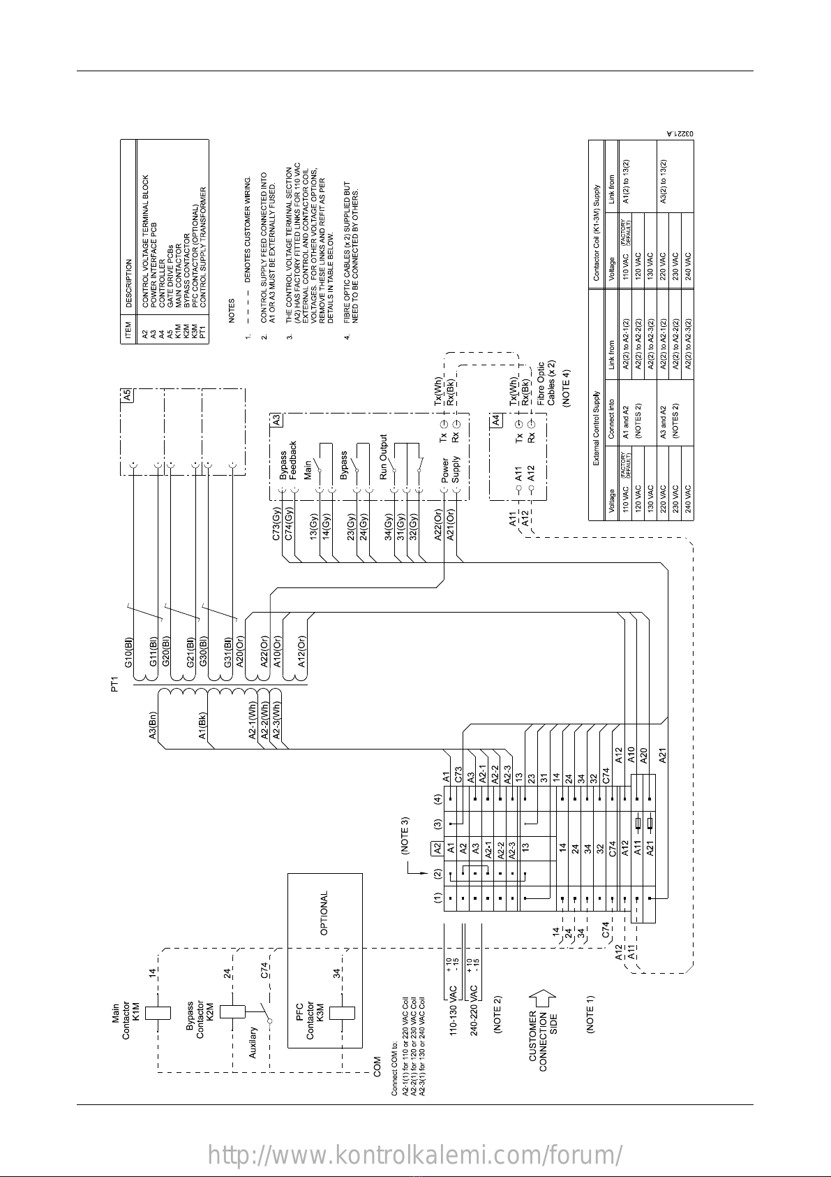
4.6 Internal Wiring
Diagram 2: Internal Wiring
http://www.kontrolkalemi.com/forum/

POWER CIRCUITS
710-03261-00A 14 MVS SERIES
Section 5 Power Circuits
5.1 Overview
MVS starters are designed to operate as part of a system including other
components. A main contactor and bypass contactor are required in all
installations. The following additional components may also be required:
•main isolator/earth switch
•"R Rated" protection fuses
•power factor correction capacitor contactor
•line inductors
•transient / overvoltage protection
•medium voltage control supply transformer
Please refer to the schematic drawings on pages 12, 13, 15 and 17 for details.
5.2 Main Contactor
A main contactor is required in all MVS Series installations. The contactor should
be selected such that the contactor's AC3 rating is greater than or equal to the full
load current rating of the connected motor.
The main contactor is associated with terminals L1, L2, L3 on the input side of the
soft starter and the coil is associated with output terminals 13, 14 of the MVS (refer
to Diagram 3).
To ensure that the potentially dangerous medium voltage area is isolated from the
low voltage control area, power is supplied to the main contactor coil from the
control voltage terminal block (refer to Diagram 2).
5.3 Bypass Contactor
A bypass contactor is required in all MVS Series installations. The contactor should
be selected such that the contactor's AC1 rating is greater than or equal to the full
load current rating of the connected motor.
The bypass contactor is associated with bypass terminals T1B, T2B, T3B on the
starter. The coil is associated with output terminals 23, 24, and the auxiliary
Normally Open contact is associated with input terminals C73, C74 of the MVS
(refer to Diagram 3).
To ensure that the potentially dangerous medium voltage area is isolated from the
low voltage control area, power is supplied to the bypass contactor coil from the
control voltage terminal block (refer to Diagram 2).
http://www.kontrolkalemi.com/forum/

POWER CIRCUITS
MVS SERIES 15 710-03261-00A
Diagram 3: Standard Power Circuit Configuration
MVS starter installation with main and bypass contactors.
T3B
BYPASS CONTACTOR
MAIN CONTACTOR
POWER INTERFACE PCB
CONTROL VOLTAGE TERMINAL BLOCK
POWER ASSEMBLY
DESCRIPTION
K2M
K1M
A3
A2
A1
ITEM
A3
A2
A1
K2M
T1B
T2B
E
L1
L2
L3
T1
T2
T3
A1
A2
A3
CONTROL
SUPPLY
13
14
23
24
C73
C74 BYPASS CONTACTOR
FEEDBACK SIGNAL
(PFC)
RUN OUTPUT
32
31
34
K2M
K1M
K2M BYPASS CONTACTOR
K1M MAIN CONTACTOR
3
M
MOTOR
http://www.kontrolkalemi.com/forum/

POWER CIRCUITS
710-03261-00A 16 MVS SERIES
5.4 Main Isolator / Earth Switch
If specified, a main isolator/ earth switch can be connected upstream of the main
contactor as shown in Diagram 4. The isolator interlocks the panel door to ensure
personnel safety.
5.5 "R Rated" Protection Fuses
If specified, "R Rated" protection fuses can be installed on the input side of the
starter to provide Type 2 coordination and short circuit protection for the motor
branch circuit. The appropriate fuse should be selected from the table below,
based on the motor's rated full load current.
Motor Rated FLC System Voltage
2.3 kV
System Voltage
3.3 ~ 4.2 kV
System Voltage
6 ~ 7.2 kV
70 A 2R
100 A 3R
130 A 4R
150 A 5R
170 A 6R
200 A 9R
230 A 12R
390 A 18R
Ferraz type code A240Rrr A480Rrr-1 A072xxDxRO-rr
Bussmann type code JCK JCL JCR-A, JCR-B
5.6 Power Factor Correction Capacitor Contactor
If power correction factor capacitors are being used, a contactor can be selected
according to the required kVAr, and should be connected upstream of the MVS soft
starter. The power factor correction capacitor contactor coil is associated with
output terminals 31, 34 of the MVS (refer to Diagram 4).
To ensure that the potentially dangerous medium voltage area is isolated from the
low voltage control area, power is supplied to the power factor correction capacitor
contactor coil from the control voltage terminal block (refer to Diagram 2).
NOTE
The capacitor bank must be connected to the input side of the MVS soft
starter.
5.7 Line Inductors
Line inductors are required if the cable run between the soft starter and the motor
is more than 200 m. Line inductors should be installed outside the panel, and
connected between terminals T1, T2, T3 of the soft starter and the motor.
5.8 Transient / Overvoltage Protection
Overvoltage protection should be installed if there is a risk of high transients at the
installation. If required, use the optional Overvoltage Protection Kit.
5.9 Medium Voltage Control Supply Transformer
The control supply for the MVS soft starter should usually be provided as a low
voltage supply (110~130 VAC or 220~240 VAC). If this is not possible, a control
supply transformer will be required. A transformer should be selected with primary
voltage matching the mains voltage and secondary voltage of 110 VAC. Use a
single phase ~ 500 VA transformer with protection fuses on both primary and
secondary side (refer to Diagram 4).
http://www.kontrolkalemi.com/forum/

POWER CIRCUITS
MVS SERIES 17 710-03261-00A
Diagram 4: Complete Power Circuit Configuration
MVS Starter installation with main contactor, bypass contactor, isolator/earth switch, fuses and medium
voltage control supply transformer. Configured for two-wire start/stop control.
http://www.kontrolkalemi.com/forum/
APPLICATION EXAMPLES
710-03261-00A 18 MVS SERIES
Section 6 Application Examples
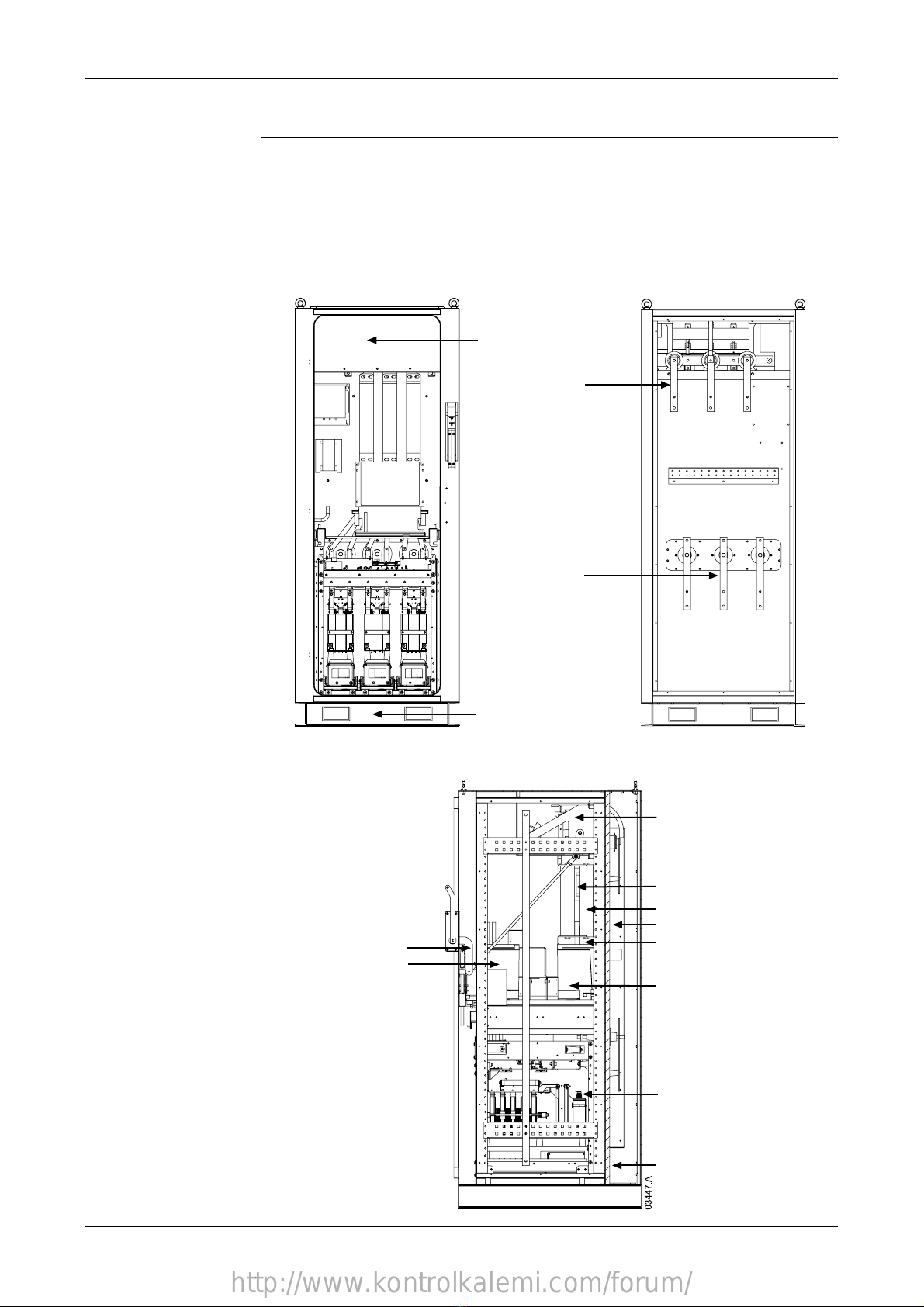
6.1 Installation into a Panel
The MVS panel permits a wide range of installation configurations. Power input
and output can be top or bottom entry and power input can be provided from either
cables or top horizontal bus bars.
The diagrams below illustrate one possible configuration for installation.
Front View
Welded steel plinth
Earth switch viewing window
Rear View
Line bus bars
Motor bus bars
Side View
Interlock mechanism
Fuses
Main contactor
Rear cabling cavity
Power assembly
Bypass contactor
Low voltage trunking
Single phase MV transformer
Three phase MV transformer
Earth / line switch
http://www.kontrolkalemi.com/forum/

NOTES
MVS SERIES 19 710-03261-00A
http://www.kontrolkalemi.com/forum/
This manual suits for next models
11
Table of contents
Other AuCom Industrial Equipment manuals

Popular Industrial Equipment manuals by other brands

GFA
GFA ELEKTROMAT KE 40.24-40,00 installation instructions

Unitary products group
Unitary products group PT8 installation manual

Hubbell
Hubbell CHANCE PSC3090323CE manual

Condair
Condair Defensor OptiSorp Installation and operating instructions

ABB
ABB HT614359 Operation manual

ABB
ABB A130-M Series Operation manual


