Audeon MCTX-16 User manual
Multi Channel Transmitter
(MCTX-16) Installation Instructions
Page 2 of 16
Multi Channel Transmitter (MCTX-16) Installation Instructions
Introduction
The Multi Channel Transmitter (MCTX-16) is designed aspart ofthe Audeon low power UHF
radio system for use in fitness, conference and exhibition centres. It is compatible with the
MCTX-8andthesinglechannelsystem(SCTX)andusesthesametransmissionfrequencies.The
transmitter has the new input module (RF16) which provides two mono RF channels. The
processor can be supplied with any number of input modules. The number of inputs can be
increased or reduced on site as required without any further modification. Additional features
include an emergencymessage evacuation announcement activated bythe fire alarm, three high
quality priority microphone inputs and a wall mounting remote control for the audio feed to the
public address system. Mono and stereo input modules can be mixed in the same processor if
required.
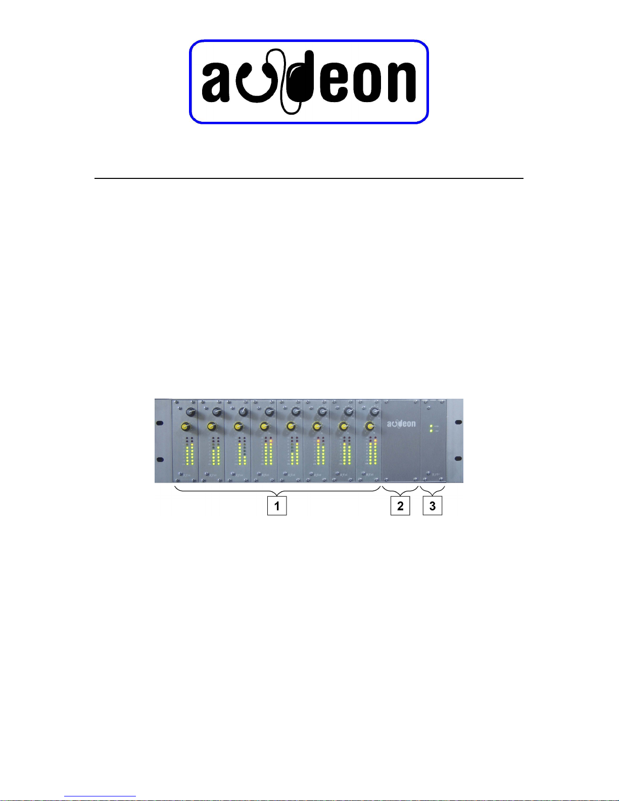
Thebasebandprocessor is housed in a standard19"cardframe with allelectronicson removable
cards.
1RF 16 or RF6 Input modules with volume control and bargraph display
2 RF 5 VHF Output amplifier and filters
EM 1 Alarm and microphone card
EM 2 Emergency message card
3 RF 9 PSU card with fuses and status LEDs
The transmitter can accept upto sixteen line level stereo audio inputs and transmits in either the
licence free ISM band or in TV channel 69 for which a licence will be required. The range of up
to 100 metres is dependanton the locationwhere reflections from metalobjects mayincrease or
decrease the range whilst absorbent objects such as walls, furniture and people will reduce the
range available.
Thisinstruction manualdescribes the installation procedures for the AudeonMCTX transmitter
pack.The pack consists of the eight channelbaseband processor, theupconverter, the aerial and
a tuned feeder cable.

Multi Channel Transmitter (MCTX) - Installation,
Commissioning and Maintenance
Page 3 of 16
Compliance
Allsystemsaretestedatthefactorybeforeshippingtoensurethattheycomplywiththefollowing
EU directives and standards:
Council Directive 89/336/EEC the EMC directive
European Standards 1) EN 50 081-1 Emission
2) EN 50 082-2 Immunity
3) EN 60 555 Conducted Emissions
Conformity Criteria 1) Radiated emissions are less than 30 dB:V/m @ 10m from the
equipment.
Conducted emissions are less than 56dB:V/m.
2) The performance of the equipment will not be impaired by a
radiated signal in the band 27MHz to 500MHz with a signal
strength 3V/m and with 80% modulation
3) TheAC powerinputcurrentharmonicsarewithinthelimitssetby
EN60555-3,-3. TheconductedRFemissionsarebelowthelimits
described in EN55 022 class B.
Council Directive 73/23/EEC The Low Voltage Directive as amended by Article 13 of Council
Directive 93/68/EEC
Council Directive 1999/5/EEC the R&TTE Directive
European Standard EN 60065
UK Interface requirements IR2030
ETSI standard EN 301 357
Council Directive 2002/95/EC the RoHS Directive
The performance of the transmitter must be checked
when the system has been installed to ensure that it
still fully complies.
Instructions for testing are included later in this
document.

Multi Channel Transmitter (MCTX) - Installation,
Commissioning and Maintenance
Page 4 of 16
Specification
Audio
Signal Input -10.0 dBu (0.245 v)
Inputimpedance 10kOhmsunbalanced(balanced available)
Input headroom +20 dB
Signal to noise ratio 80 dB
Input limiter operates at +6 dB
Noise reduction 2:1 compression - expansion (DBX)
Audio bandwidth 50 Hz to 15 kHz
Stereo System Zenith GE with 19 kHz pilot tone
Channel separation 60 dB
Radio
Output level 0 dBm (1 mW)
Output impedance 50 Ohms
Modulation system FM
Maximum deviation for 0 dBu audio input ±50 kHz
Maximum RF bandwidth (per channel) 150 kHz
Frequency stability ±1A0 kHz
RF output auto mute time After 5 minutes of no audio input signal
Radio Frequencies
ISM licence free band UHF channel 70
Channel 1 863A10 MHz
Channel 2 863A35 MHz
Channel 3 863A60 MHz
Channel 4 863A85 MHz
Channel 5 864A10 MHz
Channel 6 864A35 MHz
Channel 7 864A60 MHz
Channel 8 864A85 MHz

Multi Channel Transmitter (MCTX) - Installation,
Commissioning and Maintenance
Page 5 of 16
TV channel 69 (licence required from JFMG in UK)
Channel 9 854A60 MHz
Channel 10 855A90 MHz
Channel 11 856A90 MHz
Channel 12 857A60 MHz
Channel 13 858A70 MHz
Channel 14 859A30 MHz
Channel 15 860A20 MHz
Channel 16 861A00 MHz
Installation Instructions
Carefully unpack the contents and check to ensure that no parts of the system are missing. The
pack contains the following parts:
MCTX Baseband processor Audio input, VHF RF output and +15 v supply for the up
converter. Housed in a standard 3U 19" rack mounting
card frame.
Up converter and UHF transmitter converts the VHF RF signalinput to a UHF output which
isconnected to the aerial. The up converter should be
fixed adjacent to the aerial.
½ wave aerial Half wave dipole tuned to 864 MHz
Feeder cable A 1 metre low loss cable to connect the aerial to the up
converter.
Mains lead
Set of installation instructions
Service leaflet + service price list + FAQs - Please leave these with the customer
Should any part be missing please contact your supplier for a replacement.
Theupconverter,feeder cable andaerial havebeen tuned in the factoryfor maximumoutputand
minimumintermodulation.Theyshouldonlybeusedasaset.Failuretokeepthesettogethermay
reduce the output efficiency and cause unwanted signals to be radiated.
Warning: This equipment must be connected to earth.
Power requirements
The unit requires a230v AC mains supply. It is supplied with a mains lead without a fitted plug
so it can be wired into the equipment rack mains distribution panel. The wires should be
connected GREEN/YELLOW to Earth, BROWN to Live and BLUE to Neutral.
This equipment must be connected to earth.

Multi Channel Transmitter (MCTX) - Installation,
Commissioning and Maintenance
Page 6 of 16
Location of the aerial and the up converter
The performance of the radio system is very dependant on the location of the aerial and up
converter,apoorly sited aerialwill seriouslydegrade the performanceof the system. The signals
travel in a straight line from aerial to receiver and will be attenuated byany object in the signal
path.Choose alocation which isabove any objectwhichislikely torestrictreception oftheradio
signal, placing it well above head height will reduce theeffect of peoplewho are in the way. Try
not to have any metal objects such as steel cupboards, shelf brackets, TV sets or electric wires
near to the aerial which will cause reflections.
The up converter should be sited close to the aerial so that the 1 metre feeder cable can be
connected to both the up converter and the aerial without any sharp bends or kinks in the cable
which will cause reflections to the RF signal and create standing waves so reducing the output
signal from the aerial. At a frequencyof 864 MHz the loss in the feedercable is 1 dB per metre.
The aerial will need to be connected to the aerial socket located on the end of the up converter
usingtheBNCfeedercablesupplied.Donot betempted to cut thelength of, orreplace the feeder
cable as this is tuned in the factory for the best output signal. Changing the cable or altering its
length will seriously degrade the performance of the systemand may cause it to fail to meet the
required standards. Select the best location in the room and position the aerial so that it is
mountedvertically(with theAudeon textreadingthe correctway round) toprovide the strongest
signal.The range which you can expect is up to 100 metres butthis is dependant on other factors
such as walls, metal objects, other equipment and people, all of which will attenuate the signal.
Radio Frequency Connections
Thebasebandprocessorshould be installedin a standard19" rack enclosure. Thereare twoBNC
sockets on the rear panel which willrequire to beconnected to the up converter using RG 58 (or
similar - see appendix I) coax cable. The two connectors are colour coded red and black.
FM - BLACK is the VHF modulating signal output from the processor which is
fed to the up converter.
FC - RED has the +15v dc supply for the up converter.
It is good practice to mark the cables at both ends with red and black tape for future reference.

Multi Channel Transmitter (MCTX) - Installation,
Commissioning and Maintenance
Page 7 of 16
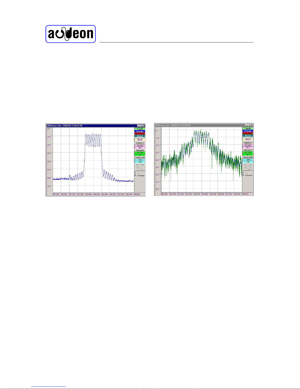
VHF input to upconverter no modulation
VHF input to upconverter 100% modulation
The systemhas been designed to allow for up to10 dB cable loss between the processor and the
up converter. To allow for cable loss of less than 10 dB an attenuator will be required in the FM
cable to compensate for the cable loss.
To select the correct attenuator value
measure the FM output of the processor,
the VHF signals should be -20 dBm ± 1
dB. Connect the cable and then measure
the signals at the up converter end.
Subtract the required up converter input
signal level of -30 dBm from the
measuredvalueto obtain the value of the
attenuator. Check that the attenuator
value is correct by measuring again on
the output of the attenuator after
attaching it to the cable at the
upconverter end, which should be below
-30 dBm. This last check will verify that
the signal level is correct, if it is not then
there may be an impedance miss-match
in the cable. The input to the up
convertermust be below -30 dBm. If it is
higher than -30 dB over modulation of
the up converter will occur and
harmonics and intermodulation will be
produced which will cause noise,
distortion and non compliance with the
standards.
Connect the attenuator and the FC cable
to the up converter. For the best
performancetheattenuatormustbeatthe
up converter end of the FM cable so that
it masks any impedance miss-match and
reduces any RF pick up in the cable run.
With the aerial connected check the radiated signal on your spectrum analyser using a second
aerial which is verticallypolarised and is located 1 metre away from the transmitter aerial check
for out of band signals. The radiated signal levelat this point should measure approximately -30
dBm. Measuring the RF signal adjacent to the transmitter aerial will produce a reading of about
-10 dB. The RF signal is attenuated by 6 dB as thedistance from thetransmitter is doubled or 20
dB as the distance increases by 10 times. At a distance of 100 metres then the signal will be
measured at approximately-60 dB. The lossfrom the receiver aerial (headphone lead) is 20 dB.
Therefore you can predict the service area of the system by adding the signal strength to the
receiver aerial loss, which in this example produces an RF signal input to the receiver of -80
dBm.Thesecalculationsareonlyaguidetowhatyoushouldexpecttoreceive,themeasurements
Multi Channel Transmitter (MCTX) - Installation,
Commissioning and Maintenance
Page 8 of 16
Overloaded UHF output
Typical UHF output
are only approximate and will be affected by adjacent objects reflecting and absorbing the
signals.
Warning:Do not connect yourspectrum analyser directlyto the output of the transmitter as the
high signal level could permanently damage the mixer diode in the analyser.
Overmodulationoftheupconverterwillproducenoiseandhighintermodand thissituation must
beavoidedtomaintaincompliancewiththeappropriatestandards.Whenviewedonthespectrum
analyser the radiated signal will be shown with high levels of noise as shown in the captured
display.
Ifyour spectrumanalyserhas the facilityto save the results do so,as this will show thatyou have
exercised due diligence when setting up the system.
It is the responsibility of the installer to ensure that the installed system fully complies with all
the technical requirements of the R&TTE directive.
Connecting the audio signals
The audio input signals should be connected to the two phono sockets for each channel using a
suitable screened lead. A nominal signal level of -10 dBu is required for full modulation of the
VCO.
The alarm input is designed to operate from a normally open volt free contact in the fire alarm
control panel. The wires should be connected between pins 2 and 3 of the XLR connector. Pin
one is for the shield of a screened cable. We recommend a balanced pair screened cable is used
for the connection to reduce the effect of any unwanted signals or interference.

Multi Channel Transmitter (MCTX) - Installation,
Commissioning and Maintenance
Page 9 of 16
The Audio output is available on a three pin male XLR connector. The connections are;
pin1 screen,
pin 2 + phase
pin 3 - phase.
The microphone inputs use a five pin female XLR connector. The connections are;
pin 1 screen
pin 2 microphone + phase
pin 3 microphone - phase
pins 4 and 5 are for the mic switch.
The muting of the audio channels can also be voice activated by speech on the microphone
channels. To select this option withdraw the mic card from the frame and move the jumper link.
Internal settings
RF16 module
The transmitter leaves the factory with the channels set to the frequencies requested by the
installer and the auto mute set off. To disable the auto mute facility move the link (JP2) .
Multi Channel Transmitter (MCTX) - Installation,
Commissioning and Maintenance
Page 10 of 16
If you wish to change the frequency of an individual channel then you will need to adjust the
frequency select switch. Rotate the small HEX switch (SW 1 for odd channels or SW2for even
channels) to the required channel. This switch is labelled in HEX so you will needto convert the
required channel number to HEX ( channel 1 = 0, channel 2 = 1, etc to channel 16 = F) before
setting it. You should not need to set or adjust any other internal control.
The audio input signal should beadjusted sothat the bargraph indicates to the yellow LED with
occasional peaks into the red LEDs. Signals which are toohigh will be limited to a maximumof
+6 dBu to avoid over modulation. The limiter is designed so that signals less than +6 dBu will
not be affected but any over the limit will sound distorted.
Emergency message module EM1 and EM2
Theemergencymessagevolume(EM2)is
preset at the factory and should not
require any adjustment. When activated
the signal will be indicated on the LED
bargraphs and it should not exceed 0dB
so that the transmitter is not over
modulated. Check the transmitter output
using a receiver and listen to see that the
audio signals are muted and the
emergency message is played.
The standard message is
“Attention please, attention please, this is an emergency. Please
leave the building calmly by the nearest exit. Do not use the lifts”
The microphone gain is set using the three preset resistors located on the front edge of the mic
card (EM 1). Turning the control clockwise will increase the gain. Do not set the input gain too
high as this will cause over modulation of the transmitter making the speech unintelligible. You
shouldalsobeawarethatclosespeaking intoamicrophone willcause “pop”where the speaker’s
breath causes the diaphragmto have excessive movementand thus high signal levels will be fed
to the transmitter. Check the transmitter output using a receiver and listen to see that the audio
signals are muted and the microphone message is heard.
The mic inputs have priority switching to enable senior management to take control in case of
an emergency. All the mic inputs will override the emergency message. The order of priorityis
for mic 2 to override mic1 while mic3 overrides mic2 and mic 1.

Multi Channel Transmitter (MCTX) - Installation,
Commissioning and Maintenance
Page 11 of 16
Listening tests
After you have powered the transmitter walk round the venue to check the quality of reception
andcoverage.Youshouldreceivesignalswithinaradiusof100metresfromtheaerialdepending
on the layout of the building and objects within the room. Check for dead spots which may be
caused by obstructions such as metal pillars, cupboards or steel work which are in the line of
sight of the transmitter or are causing reflections. If you do have some areas of poor signal
reception consider moving the receiver (a small distance is all that may be required) or if you
have a lot of problems consider relocating the aerial.

Multi Channel Transmitter (MCTX) - Installation,
Commissioning and Maintenance
Page 12 of 16
Troubleshooting
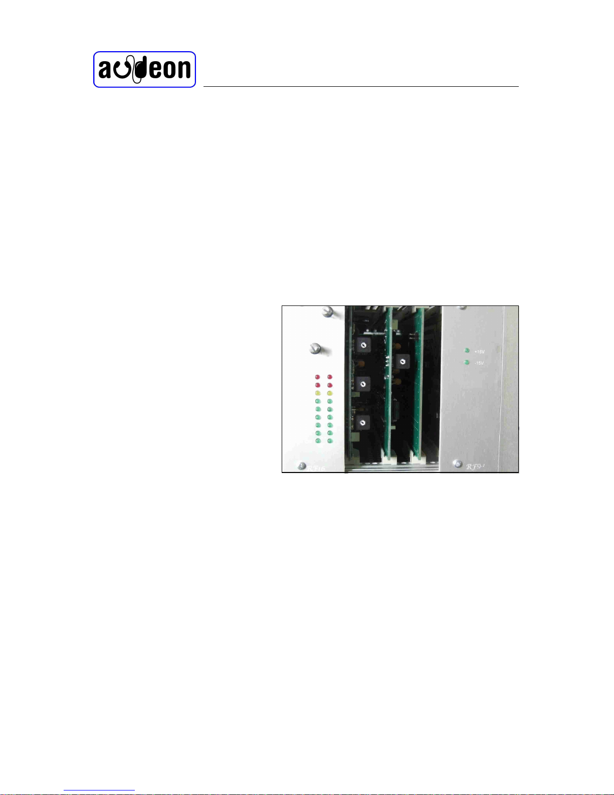
Power LEDs do not light
Only one LED is illuminated on
the PSU
There is no signal in the receiver
The programs are received on the
wrong channel and some are
missing
One channel is missing
One channel is distorted
The audio signal sounds as if
there is too much bass and
pumps.
Check that the power is connected to the transmitter, is the mains plug
connected? Is the mains fuse OK? Check the DC fuses in the power supply
card (RF9).
Check the DC fuses on the power supply card (RF9) and replace if faulty. If
thepositive LED is notilluminated remove the remote power feed cable to the
upconverter to see if there is a cable fault. The regulators in the PSU have
short circuit protection so they will shut down underfault conditions. Remove
the input cards (RF6) one at a time to see if one of them has a fault, the LED
on the PSU will illuminate once the fault has cleared. Remove the RF output
card (RF5) to see if it is faulty. If one of the cards is faulty obtain a
replacement.
Try another receiver. Check that the volume controls on the channels are
turned up and that there is an audio signal on the input which should show on
the bargraph meter. Check the +15vDC output (FC) of the baseband
processor. Check the VHF output (FM) of the baseband processor with the
spectrum analyser.Check the+15vDC (FC)into theupconverter. Measure the
VHF signal into the upconverter. Check to see if the RF output is being
radiated using the spectrum analyser and an aerial. Check that the aerial is
connected. Measure the UHF output of the upconverter, if it is missing the
upconverter is faulty so obtain a replacement. You may see an RF signal on
the spectrum analyser but it is the wrongfrequency, this will indicate that the
PLL for the local VCO is not locked, obtain a replacement upconverter.
Please note that the upconverter, feeder cable and aerial are all tuned in the
factory so they should be changed as a set.
This can be caused by either the PLL in the upconverter not locking or the
PLL in the receiver not locking. Try another receiver first to check the fault is
not the receiver. Check the RF signal with the spectrum analyser for correct
channel frequencies, a test aerial can be used for this as the signal level is not
in question.
Check the RF signals using the test aerial and spectrum analyser. Is one
missing or off frequency? Check the VHF output of the baseband processor,
is one channel missing or off frequency. If it is off frequency the PLL hasn’t
locked - replace the channel module (RF6). If the carrier signal is missing
then the channel card is faulty, Check to see that it is fully home in the card
frame. Has the coax insert in the card frame connector been displaced? If so
push it home from the rear. This will require you to remove the top rear cover.
In early units there was a small problem with the coax inserts not aligning with
the module connector and that resulted in the insert being pushed out -if you
are servicing an old unit please check for this and proceed as above.
Is the signal too high and the limiter is operating? Check the bargraph level.
The signal should go to the yellow LED with occasional peaks into the red.
This canbecaused whenthe noise reduction is linked out on theinput module.
Check links JP3 and JP4 are set correct. This should only happen in error as
thepresentsystem does nothave thecapability to transmit and receive without
noise reduction.

Multi Channel Transmitter (MCTX) - Installation,
Commissioning and Maintenance
Page 13 of 16
The audio signal is noisy
All the audio signals are noisy
and reception is poor
There are areas of poor reception
and dead spots
The received signal is in mono
The signal fades as people walk
round the room
The transmitter causes
interference on an adjacent TV or
radio.
No audio signal
The received signal has a low
frequency hum
The volume on one channel of
the receiver is low
The receiver is too far from the transmitter. The aerial has been mounted in a
poorlocationor ishorizontalinsteadofvertical. There are objects in the signal
path. You may consider transmitting in mono which will improve the signal
to noise ratio.
The upconverter maybe overloaded,check the outputof the transmitter using
the test aerial and a spectrum analyser (see output displays shown above). Is
there an attenuator in the VHF feed to the upconverter? Is it the correct value?
There are reflections on theroom which are causing phase cancelling insome
areas. Either re-site the transmitter aerial or re-site the receivers.
The transmitter is shipped with all the channels in mono because many of the
audio sources are in mono. A mono signal will have a better signal to noise
ratio and provides coverage over a greater distance compared to a stereo
system.
Check the signal strength with the test aerial and spectrum analyser. If it is
poor check the output of the upconverter which should be 0dBM (remember
to use a 20 dB attenuator at this point to protect the analyser). If it is correct
then increasethe height of the transmitter aerial or re-site it.Low ceilings may
also cause this problem.
The transmitter may be too close to the TV or radio receiver. If the TV
installation is poor or the received TV signal is weak. Some TV distribution
systems use passive splitters which reduce the signal into theTV set. The TV
distribution cable may have a poor screen or earth connection. The TV
distribution amplifiers or splitters do not have sufficient immunity to RF
signals.
Check the input bargraphs for a signal. Is the input volume control set too
low? Are the input signal leads connected? Is the audio source switched on?
Check for hum loops (multiple earths) on the installation .
Check the input channel volume control
User maintenance
The venue staff should be instructed on how to operate the transmitter. The only user controls
are the channel volume controls which can be adjusted to accommodate different inputsignals.
You shouldemphasise that there areno usercontrols inside theunits which have been set up for
their optimum performance. Should theyinterfere with thetransmitter itwill no longer comply
with the standard for wireless audio and the warranty will be void.

Multi Channel Transmitter (MCTX) - Installation,
Commissioning and Maintenance
Page 14 of 16
Spare parts
Spare cards for the processor are available fromthe factory but will only be sold to authorised
dealers. Cards can be removed and inserted into the card frame without the need to remove
power. If one input card is faulty it can be removed without affecting the other channels.
The upconverter, feedercable and aerial are only suppled as a set. Theyare tuned in the factory
for the best performance and should always be installed as a set. Mixing these components may
cause the system to radiate unwanted signals.
Service
Inthe UKAudeonhas a dedicated service line (0113 252 5582) toco-ordinate maintenance and
repairs of Audeon equipment. The operator should be made aware of the benefits of expert
adviceandsupport.Thetelephonelineisstaffedbyexperiencedengineerswhoarefamiliarwith
the Audeon range of products. They can provide advice, on line help and will arrange for
maintenancefrom you, the dealer if required. A poster is provided with the help line telephone
number for display on the staff notice board.
User Instruction
Before leaving the installation ensure that the staff are;
familiar with the system.
know about it’s features and benefits.
they can demonstrate it to the users.
they know how to maintain it and keep it clean.
they can change the headphone lead.
they know how to obtain service for the system.
they can diagnose simple faults.
Finally
If you have left a site log book for the installation, complete the first entry.
Remove any waste material. The carton for the transmitter can be reused to return any faulty
units to the factory. Please save it.

Multi Channel Transmitter (MCTX) - Installation,
Commissioning and Maintenance
Page 15 of 16
Appendix i
Coax Cable Losses
Cable Impedance Loss per Metre
@ 100 MHz @ 1000 MHz
RG 58 50 ohms 0.21 dB 0.76 dB
RG 223 50 ohms 0.14 dB 0.29 dB
UR M43 50 ohms 0.13 dB 0.46 dB
UR M67 50 ohms 0.07 dB 0.25 dB
UR M70 75 ohms 0.15 dB 0.52 dB
UR M76 50 ohms 0.16 dB 0.53 dB
CT100 75 ohms 0.06 dB 0.20 dB
Appendix ii
RF absorption at 1000 MHz of common building materials
Single brick wall (225 mm - 9")
Half brick wall (110 mm - 4.5")
Breeze block wall 225 mm
Breeze block wall 110 mm
Plasterboard partition (double layer)
Chipboard partition (double layer)
Window (4 mm glass)
Window (4 mm polycarbonate)
Appendix iii
Extract from: ETSI EN 301 357 Technical characteristics and test methods for analogue cordless wideband
audio in the 863 MHz to 865 MHz frequency range
Section 8 Methods of measurement and limits for transmitter parameters
8.1.3 Frequency error - limit ±40 KHz
8.2.3 Carrier power - limit 10 mW (+10 dBm)
8.3.3 Bandwidth - limit ±150kHz @ -46 dBc
8.3.4 Edge of band limits
At no time shall any part of the occupied bandwidth mask above the -46 dBc point fall outside
the edges of the band 863 MHz to 865 MHz.
8.5.3 Transmitter shut off
The carrier output power shall be reduced by at least 30 dB in less than 5 minutes after the
modulation is removed.

Multi Channel Transmitter (MCTX) - Installation,
Commissioning and Maintenance
Page 16 of 16
Audeon products are designed by John Varley
and are manufactured in the UK by
M-Jay Electronics Limited
Albion Mills, Church Street, Morley, Leeds. LS27 8LY
Phone +44 113 252 4956
Fax +44 113 252 5542
Service +44 113 252 5582
e-mail to: service@audeon.co.uk
www.audeon.co.uk
www.m-jay.co.uk/audeon
Table of contents


