manuals.online logo
Brands
  1. Home
  2. •
  3. Brands
  4. •
  5. Audio Technica
  6. •
  7. Transmitter
  8. •
  9. Audio Technica ATW-T1006 User manual

Audio Technica ATW-T1006 User manual

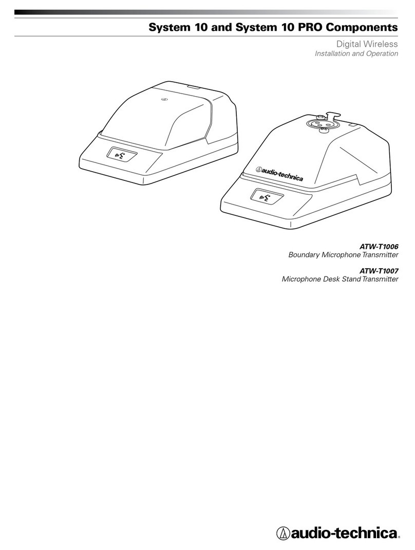
ATW-T1006
System 10 Boundary Microphone/Transmitter
Features
• Cardioid condenser boundary microphone/transmitter pairs with
any System 10 or System 10 PRO digital wireless receiver
• Digital 24-bit/48 kHz wireless operation for ultimate sound quality
and dependable performance
• Operates in the 2.4 GHz range—completely free fromTV
interference
• User switch can be set to toggle between talk and mute modes,
or function as a press-to-talk or press-to-mute button
• Gain Control switch allows selection of three input gain levels:
-6 dB (for loudest voices), 0 dB and +6 dB (for softest voices)
• Two red/green LEDs—one visible from the front of the unit, the
other from the rear—indicate toggle/talk/mute mode, battery
level, and charging status
• Switchable low-cut lter
• System ID Display located on bottom of unit
• Automatic frequency selection for seamless, interference-free
operation
Description
The ATW-T1006 is a digital wireless condenser microphone/transmitter
with a cardioid polar pattern. It is designed for surface-mount applications
such as high-quality sound reinforcement, conferencing, distance learning
and other demanding sound pickup applications.
The transmitter features a touch-sensitive user switch and two red/green
LED status indicators—one integrated into the user switch on the front
of the unit (LED 1), the other congured to display on both the top and
rear of the unit (LED 2), allowing the transmitter status to be viewed by
those seated opposite the user. The user switch mutes and unmutes the
transmitter. It can be set to toggle between live and muted audio (toggle
on/off), to permit live audio only while the switch is pressed (press to
talk), or to mute the audio while the switch is pressed (press to mute).
A power button is located on the bottom of the unit, along with four
recessed control buttons and a System ID Display. The recessed buttons
allow user to pair the transmitter with a System 10 receiver, switch
between Standard and Conference modes, lock and unlock the mute
function, and congure the gain and low-cut lter. The System ID Display
shows the System ID number, mode (Standard or Conference) and mute
lock status.
The integral 80 Hz low-cut lter provides easy switching from a at
frequency response to a low-end roll-off. The roll-off position reduces
the pickup of low-frequency ambient noise (such as trafc, air-handling
systems, etc.), room reverberation and mechanically coupled vibrations.
The three-position input gain level selector permits trim adjustment to
accommodate louder and softer voices.
The transmitter’s cardioid polar pattern provides a 120° angle of
acceptance (cardioid in hemisphere above mounting surface).
The transmitter features a low-reectance black nish. Its heavy die-cast
case and non-slip silicone foam bottom pads minimize coupling of surface
vibration to the transmitter.
Operation and Maintenance
The ATW-T1006 is powered by a 3.7V rechargeable lithium-ion battery.
The transmitter is turned on by pressing and holding the Power button
on the bottom of the unit. The electronics in the transmitter take up to 30
seconds to stabilize after power is applied.
The transmitter should be placed on a
at, unobstructed mounting surface,
with the front of the transmitter
facing the sound source. The sound
source should not be below, or higher
than 60° above, the plane of the
mounting surface.
The transmitter operates in two different modes: Standard and
Conference. In Standard mode, which is the default, both of the
transmitter’s LEDs will illuminate green when the transmitter is on and
will illuminate red when the transmitter is muted. In Conference mode,
both LEDs will illuminate red when the transmitter is on and will not
illuminate at all when the transmitter is muted. In both modes, when
the transmitter power is off and the charging cable is plugged into the
transmitter, LED 1 will not illuminate, and LED 2 will illuminate red
while the battery is charging and illuminate green once the battery is
fully charged. (See LED Function chart below for complete LED lighting
scheme.)
The transmitter can be switched between Standard and Conference
modes by pressing and holding the recessed Switch Function button and,
while continuing to hold it, pressing and holding the Power button. After a
few seconds, the mode will change and the System ID Display will briey
show an “A” for Standard mode or a “C” for Conference mode.
The transmitter’s mute function can be locked and unlocked by pressing
the Pair and Power buttons on a transmitter that has been turned off.
When locked, a dot that normally appears on the System ID Display will
not appear and the LED below the Switch Function button will not be lit.
The settings for the user switch, low-cut lter and input gain level, can all
be adjusted by pressing the appropriate recessed button on the bottom
of the transmitter.
The user switch has three settings that can be chosen by pressing the
recessed Switch Function button. The default setting is TOGGLE ON/OFF
(with audio on at power up). Pressing the Switch Function button once
selects MOM. ON (momentary on), wherein the audio will be on only
while the user switch is being pressed (press to talk). Pressing the button
a second time selects MOM. OFF (momentary off), wherein the audio
will be muted while the user switch is being pressed (press to mute).
Pressing the button a third time cycles the setting back to the default.
The LED below the Switch Function button illuminates green for TOGGLE,
orange for MOM. ON and red for MOM. OFF.
There are three input gain levels that can be selected: -6 dB (for loudest
voices), 0 dB and +6 dB (for softest voices). The default setting is 0 dB.
Pressing the recessed Gain button on the bottom of the transmitter
adjusts the gain level. Pressing the button once changes the level from
0 dB to +6 dB, pressing it again changes the level to -6 dB and pressing
it a third time returns the level to 0 dB. The LED below the Gain button
illuminates green for -6 dB, orange for 0 dB and red for +6 dB.
60°
IDEAL
WORKING
ANGLE
ATW-T1006
10 mW
Fixed-charge back plate, permanently
polarized condenser
Half-cardioid (cardioid in hemisphere
above mounting surface)
20-20,000 Hz
80 Hz, 18 dB/octave
139 dB SPL, 1 kHz at 1% T.H.D.
Touch-sensitive user switch function:
toggle (mute on power up), momentary
on, momentary off; Low-cut lter: at,
roll-off; Gain: -6 dB, 0 dB, +6 dB
3.7 V rechargeable Li-ion battery
9 hours
Depending on environmental conditions
4 hours 30 minutes
Depending on environmental conditions
An empty battery will recharge 90% in 2 hours.
96.1mm (3.78") W × 38.0mm (1.50") H ×
122.8mm (4.83") D
408 grams (14.4 oz)
AC adapter (USB-type), USB cable
RF Power output
Element
Polar pattern
Frequency response
Low frequency roll-off
Maximum input sound level
Switches
Internal battery
Battery life
Battery charging time
Dimensions
Weight
Accessory included
In the interest of standards development, A.T.U.S.
offers full details on its test methods to other industry
professionals on request.
1 Pascal = 10 dynes/cm2= 10 microbars = 94 dB SPL
1Typical, A-weighted, using Audio Precision System One.
Specications are subject to change without notice.
Specications
Audio-Technica Corporation
audio-technica.com ©2016 Audio-Technica 0001-0310-00
The low-cut lter can be turned on and off by pressing the recessed Low
Cut button on the bottom of the transmitter. The lter is off by default.
The LED below the Low Cut button illuminates red when the lter is off,
green when it is on.
All LEDs on the bottom of the transmitter will turn off seven seconds
after the last button is pressed. Pressing any button will cause the LEDs
to relight.
The settings can be restored to the factory default by pushing and
holding the Low Cut button and, while holding it, pushing and holding
the Power button. The three LEDs on the bottom of the transmitter will
rapidly blink green for two seconds and then illuminate according to
default settings once the defaults have been restored.
Note: All settings will be restored except for the System ID number. This
number and pairing with the receiver will be retained.
Avoid leaving the transmitter in the open sun or in areas where
temperatures exceed 110° F (43° C) for extended periods. Extremely high
humidity should also be avoided.
Note: Placing any object on a surface (such as a conference table) before
its nish is fully cured may result in damage to the nish.
Architect’s and Engineer’s Specications
The ATW-T1006 microphone/transmitter shall be a xed-charge
condenser designed for use in surface-mount boundary applications as
part of a digital wireless microphone system operating in the 2.4 GHz
range. It shall be capable of automatically adjusting its frequency to avoid
interference. It shall have a frequency response of 20 Hz to 20,000 Hz
and a cardioid polar pattern. The transmitter shall be capable of handling
sound input levels up to 139 dB.
The transmitter shall be equipped with a touch-sensitive user switch
and a corresponding Switch Function button. The Switch Function button
shall allow selection of user switch settings: toggle between live and
muted audio (toggle on/off); permit live audio only while the switch is
pressed (press to talk); mute the audio while the switch is pressed (press
to mute). Two red/green LED status indicators shall be provided – one
integrated into the user switch on the front of the unit (LED 1), the other
bent in an L-shape to display on both the top and rear of the unit (LED 2).
A pairing switch shall allow the transmitter to be paired with any System
10 receiver. An 80 Hz “low cut” switch shall be provided to tailor the low-
frequency response to minimize pickup of unwanted sounds. And there
shall be three selectable gain levels: -6 dB, 0 dB, and +6 dB.
The transmitter shall operate in two different modes: Standard and
Conference. In Standard mode, which is the default, both of the
transmitter’s LEDs shall illuminate green when the transmitter is on and
shall illuminate red when the transmitter is muted. In Conference mode,
both LEDs shall illuminate red when the transmitter is on and shall not
illuminate at all when the transmitter is muted. When the transmitter
power is off and the charging cable is plugged into the transmitter, LED
1 shall not illuminate, and LED 2 shall illuminate red while the battery is
charging and illuminate green once the battery is fully charged.
It shall be possible to electrically lock the transmitter mute function. A
backlit LCD display shall be provided to show System ID number and
mute lock status.
The transmitter shall be powered by a 3.7 V rechargeable lithium-ion
battery. An AC adapter (USB-type) and USB cable shall be included to
recharge the battery.
The transmitter shall have a maximum width of 96.1 mm (3.78"), a
maximum length of 122.8 mm (4.83") and a maximum height of 38.0 mm
LED Function
Standard Mode Conference Mode
Condition Transmitter
Power LED 1 LED 2 LED 1 LED 2
Not linked with Receiver On Red/Green
Alternate
Green/Red
Alternate
Red/Green
Alternate
Green/Red
Alternate
Initialize/Toggle Mode On Green Green Red Red
Initialize/Press to Talk On Red Red Off Off
Initialize/Press to Mute On Green Green Red Red
Mic Mute On Red Red Off Off
Mic Talk On Green Green Red Red
Charging/Mic Mute On Red Red Off Off
Charging/Mic Talk On Green Green Red Red
Fully Charged/Mic Mute On Red Red Off Off
Fully Charged/Mic Talk On Green Green Red Red
Low Battery/Mic Mute On Red Blink Red Blink Off Red Blink
Low Battery/Mic Talk On Green Blink Green Blink Red Blink Red Blink
Charging Off Off Red Off Red
Fully Charged Off Off Green Off Green
(1.50"). Weight shall be 408 g (14.4 oz). The transmitter shall be housed
in a die-cast case with a perforated steel grille. Finish shall be low-
reectance black.
The Audio-Technica ATW-T1006 is specied.
LED
2LED
1

Other Audio Technica Transmitter manuals

Audio Technica ATW-T1006 Owner's manual

Audio Technica

Audio Technica ATW-T1006 Owner's manual

Audio Technica ESW-T211 Owner's manual

Audio Technica

Audio Technica ESW-T211 Owner's manual

Audio Technica ATW-T94 Owner's manual

Audio Technica

Audio Technica ATW-T94 Owner's manual

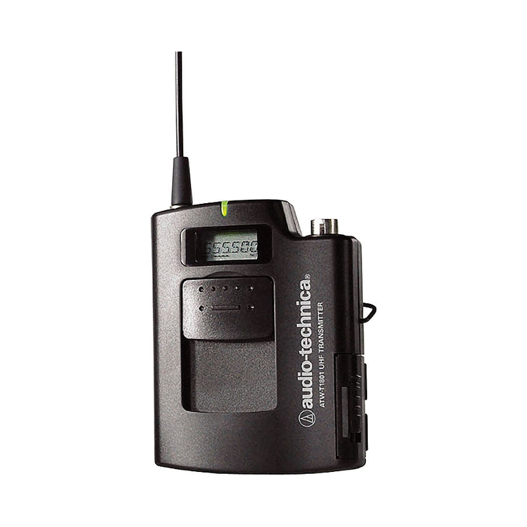
Audio Technica ATW-T1801 User manual

Audio Technica

Audio Technica ATW-T1801 User manual

Audio Technica BP24 Bodypack Manual

Audio Technica

Audio Technica BP24 Bodypack Manual

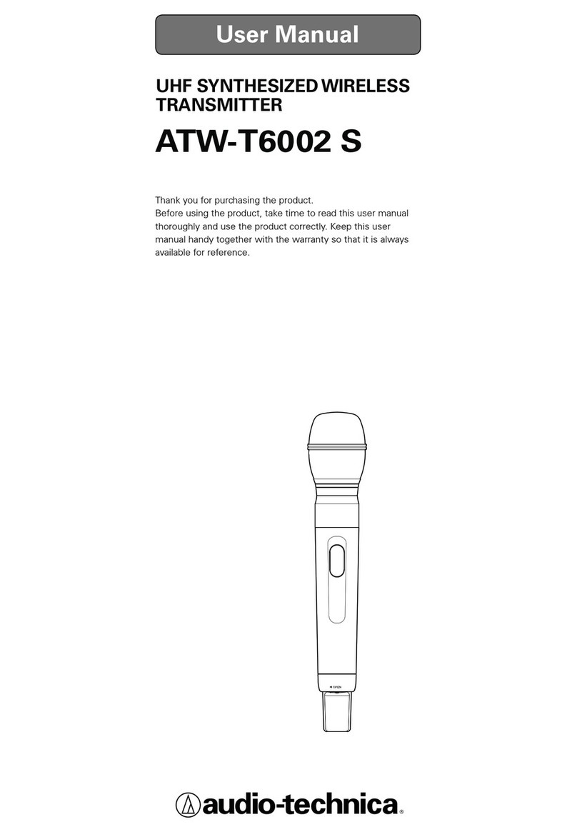
Audio Technica ATW-T6002 S User manual

Audio Technica

Audio Technica ATW-T6002 S User manual

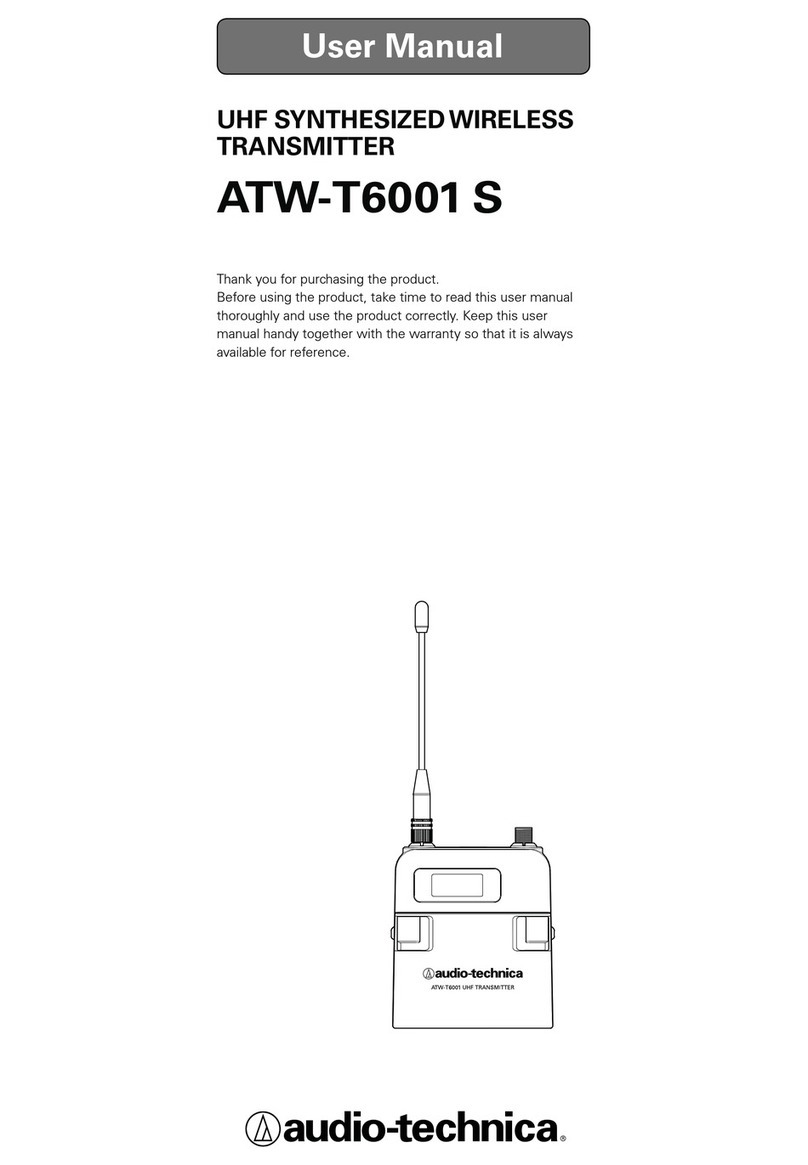
Audio Technica ATW-T6001 S User manual

Audio Technica

Audio Technica ATW-T6001 S User manual

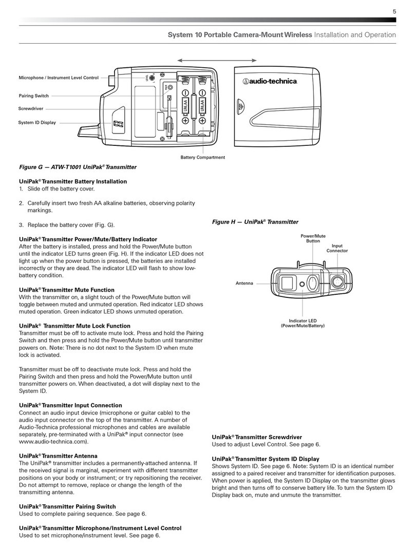
Audio Technica Uno-Pak ATW-T1001 Programming manual

Audio Technica

Audio Technica Uno-Pak ATW-T1001 Programming manual

Audio Technica ESW-T212 Owner's manual

Audio Technica

Audio Technica ESW-T212 Owner's manual

Audio Technica ATW-T1007 User manual

Audio Technica

Audio Technica ATW-T1007 User manual

Audio Technica ATW-T1006 Owner's manual

Audio Technica

Audio Technica ATW-T1006 Owner's manual

Audio Technica UniPak ATW-T93 Owner's manual

Audio Technica

Audio Technica UniPak ATW-T93 Owner's manual

Audio Technica ATW-T6001 S User manual

Audio Technica

Audio Technica ATW-T6001 S User manual

Popular Transmitter manuals by other brands

Novatech 1730 Series Reference manual

Novatech

Novatech 1730 Series Reference manual

Endress+Hauser Proline 300 Brief operating instructions

Endress+Hauser

Endress+Hauser Proline 300 Brief operating instructions

RKI M2A Operator's manual

RKI

RKI M2A Operator's manual

Winters LM6 Installation and operating manual

Winters

Winters LM6 Installation and operating manual

Kramer SWT3-41-U-T user manual

Kramer

Kramer SWT3-41-U-T user manual

Gude Expert Opto Bridge 0404 manual

Gude

Gude Expert Opto Bridge 0404 manual

HomePro ZIR010 quick guide

HomePro

HomePro ZIR010 quick guide

Dwyer Instruments 607 Series Specifications-installation and operating instructions

Dwyer Instruments

Dwyer Instruments 607 Series Specifications-installation and operating instructions

Beck 985V Series manual

Beck

Beck 985V Series manual

Minco Temptran TT809 Installation and operating instructions

Minco

Minco Temptran TT809 Installation and operating instructions

Long Range Systems T74USB user manual

Long Range Systems

Long Range Systems T74USB user manual

Verint S1704e installation guide

Verint

Verint S1704e installation guide

Endress+Hauser CM14 operating instructions

Endress+Hauser

Endress+Hauser CM14 operating instructions

Geo Web Pack quick start guide

Geo

Geo Web Pack quick start guide

Harris FM-10H3 Technical manual

Harris

Harris FM-10H3 Technical manual

Emerson Rosemount 326L quick start guide

Emerson

Emerson Rosemount 326L quick start guide

Panduit Atlona AT-HDVS-200-TX-WP installation guide

Panduit

Panduit Atlona AT-HDVS-200-TX-WP installation guide

Regin HTDT2500 Instruction

Regin

Regin HTDT2500 Instruction

manuals.online logo
manuals.online logoBrands
  • About & Mission
  • Contact us
  • Privacy Policy
  • Terms and Conditions

Copyright 2025 Manuals.Online. All Rights Reserved.