Audio Design Associates PTM-3245 User manual

PTM-3245
Power Amplifier
Installation Manual

2
Audio Design Associates
www.ada-usa.com
PTM-3245
www.ada-usa.com 3
Table of Contents
Figure 1: PTM-3245 Front and Rear Panel Drawings -----------------------------------------------3
Welcome and Thank You------------------------------------------------------------------------------------4
Unpacking and Inspecting the PTM-324----------------------------------------------------------------4
Placement Guidelines for the PTM-3245 ---------------------------------------------------------------4
Input Connections to the PTM-3245 ---------------------------------------------------------------------5
Speaker Connections to the PTM-3245-----------------------------------------------------------------7
Providing Power to the PTM-3245------------------------------------------------------------------------8
Maintaining Your ADA Amplier ---------------------------------------------------------------------------6
AC Line Voltage -----------------------------------------------------------------------------------------------7
Troubleshooting Chart ---------------------------------------------------------------------------------------10
If All Else Fails –Call Us for Help--------------------------------------------------------------------------10
Warranty and Returning Your PTM-3245 to ADA -----------------------------------------------------11
PTM-3245 Specications -----------------------------------------------------------------------------------12
Features of the ADA PTM-3245 Power Amplier
Thirty-two channels of Amplication Powers up to Sixteen Zones
40 Watts Per Channel into 8 Ω, Less than 0.08% THD
60 Watts Per Channel into 4 Ω, Less than 0.1% THD
Stable for Long-Term 2 Ω Operation to Drive Multiple Speakers
Independent Triggering Capability for Each Channel Pair
High Current Power Supply
Monolithic IC Output Stages
Rack Mountable
Low Noise Fan Cooling for Long Term Reliability
Removable IEC AC Cord
Handcrafted in the U.S.A.
Audio Design Associates 602-610 Mamaroneck Ave. White Plains, New York 10605 (800) HD-AUDIO (432-8346)
HANDCRAFTED WITH
PRIDE IN THE U.S.A.

2
Audio Design Associates
www.ada-usa.com
PTM-3245
www.ada-usa.com 3
PTM-3245 MADE IN U.S.A.
POWER
ON
OFF
Gnd
Zn 6
Zn 5
Zn 14
Zn 13
Zn 4
Zn 3
Zn 2
Zn 1
Gnd
Zn 12
Zn 11
Zn 16
Zn 15
Zn 10
Zn 9
Zn 8
Zn 7
Bypass Trigger
Zone Triggers
Zones 1-6, 13 & 14Zones 7-12, 15 & 16
Connect
to P-16
Zone Triggers
on Suite-16
230V~ 5 ASB
115V~ 10 ASB
MAIN FUSE
230V~
1/10 ASB
115V~
2/10 ASB
STBY FUSE
CAUTION
RISK OF ELECTRIC SHOCK
DO NOT OPEN
ATTENTION!
RISQUE DE CHOC ELECTRIQUE.
NE PAS OUVRIR
MADE IN U.S.A.
230V
115 V
115 V
230V
115V
115V
L
R
ZONE 1
16-2Ω
+ L - - R +
ZONE 2
16-2Ω
10K 10K
L
R
+ L - - R +
ZONE 3
16-2Ω
+ L - - R +
ZONE 4
16-2Ω
10K 10K
L
R
+ L - - R +
ZONE 5
16-2Ω
+ L - - R +
ZONE 6
16-2Ω
10K 10K
L
R
+ L - - R +
ZONE 7
16-2Ω
+ L - - R +
ZONE 8
16-2Ω
10K 10K
R
L
ZONE 9
16-2Ω
+ R - - L +
ZONE 10
16-2Ω
10K 10K
R
L
+ R - - L +
ZONE 11
16-2Ω
+ R - - L +
ZONE 12
16-2Ω
10K 10K
R
L
+ R - - L +
ZONE 13
16-2Ω
+ R - - L +
ZONE 14
16-2Ω
10K 10K
R
L
+ R - - L +
ZONE 15
16-2Ω
+ R - - L +
ZONE 16
16-2Ω
10K 10K
1200
WATTS
MAX
PTM-3245
32 Channel Power Amp
Warning! Do Not Short Outputs
WARNING! Risk Of Hazardous Energy!
Make Proper Connections.
CAUTION: Disconnect Supply Cord Before Servicing.
ATTENTION: Debrancher Avant Le Depannage.
Typical Power: 250-600 Watts
Ultimate Max. Power: 1200 Watts
Average Thermal Load: 2048 BTU/Hr
4 3 2 14 3 2 14 3 2 14 3 2 14 3 2 14 3 2 14 3 2 1
1 2 3 4 1 2 3 41 2 3 41 2 3 41 2 3 41 2 3 41 2 3 4
1 2 3 4
1 2 3 4
Power Switch
Speaker Connectors
Plugged into Zones 1 and 9
Unterminated
Speaker Connector
Zone 11
RCA Input Jacks
Rack Mount Holes
DB-9 Trigger
Connectors
IEC 65
AC Receptacle
DC Trigger
Activation
Switch
High Voltage
Conversion
Switch
Low Voltage
Conversion
Switch
1 2 3 4
1 2 3 4
Figure 1: ADA PTM-3245 Front and Rear Panel Drawings

4
Audio Design Associates
www.ada-usa.com
PTM-3245
www.ada-usa.com 5
Welcome and Thank You for Selecting ADA
The ADA PTM-3245 power amplier is a major breakthrough in power amplier technology. Hand
crafted in the United States to the strict quality and performance standards established by Audio
Design Associates, the PTM-3245 is the rst thirty-two-channel power amplier ever designed for
multichannel applications.
At ADA, we have been designing and building high-performance audio components for use in custom
installation applications for over twenty-ve years. We’re proud to offer this exceptional audio component
that will provide many years of enjoyment and dependability.
The PTM-3245 can be congured in many different ways and can also be programmed for automated
operation. We strongly encourage you to read this entire manual to learn all of its advanced features
and capabilities and how to properly connect it to your specic system.
Keeping Records for Future Reference
Record the serial number located on the back of your amplier in the section below. Also note your
dealer’s name, phone number, and date of purchase. We recommend that you keep your purchase receipt
with this manual you may need to refer to this information in the future.
Serial #: ______________________________ ADA Dealer: ___________________________
Phone Number________________________ Date of Purchase: ________________________
Unpacking and Inspecting the PTM-3245
Unpack your PTM-3245 from the shipping carton and remove the enclosed AC power cord. While
you are unpacking the amplier, inspect it thoroughly for possible shipping damage. If you see any,
contact ADA for further instructions. If possible, save and store both the carton and the packing inserts
for possible future transport.
Placement Guidelines for Your PTM-3245
Power ampliers are usually heavier and generate more heat than other components. To avoid damage
to the PTM-3245 or other equipment and to reduce risk of re, follow these guidelines:
• Do not obstruct the cooling fan or any of the vent openings.
• Do not block the front of the PTM-3245 behind closed cabinet doors during use.
• If you have ordered the Select version of the PTM-3245 for shelf mounting, place the
PTM-3245 on a separate shelf that will adequately support its weight.

4
Audio Design Associates
www.ada-usa.com
PTM-3245
www.ada-usa.com 5
Rack Mounting Your ADA PTM-3245
When mounted in a in a standard 19" equipment rack, the PTM-3245 chassis and front panel height
occupies three rack spaces (5 1/4" or 176 mm). A single standard rack space allows 1-3/4" vertical inches
in a 19-inch wide equipment rack. This measurement standard was developed by the EIA (Electronic
Industries Association) so manufacturers of electronic components and equipment racks could build
products in standardized heights that would t in a uniform space.
We strongly recommend that you have someone hold the PTM-3245 in place while you screw it into
the rack. You should use nylon shoulder washers in front and behind the faceplate this will help the
unit from scratching and also prevent ground loops.
Please call ADA if you need additional advice about the placement or mounting of the PTM-3245.
Input Connections to the PTM-3245
The input connections on the rear panel of the PTM-3245 are labeled to correspond to sixteen pairs.
This makes it easy to identify each two-channel stereo zone. Zones 1-8 are located along the top row
and zones 9-16 are located along the bottom row. If you plan to split any stereo pairs for mono operation,
we recommend you keep the mono channels grouped for easy identication.
Required Input Cables:
You will need one shielded interconnect cable terminated with RCA plugs on each for each channel of
the PTM-3245 you plan to use or a shielded interconnect cable for each two-channel stereo zone.
IMPORTANT NOTE: Do not use “directional cables” when connecting the PTM3245 to a controller or
preamplier. These cables often leave the shield disconnected at one end, which can cause ground loops
and subsequent 60 Hz hum. Directional cables are usually labeled with arrows along the insulation to
identify which end to connect to the source.
Recommendations Before Connecting Inputs
• Leave the AC cord on the PTM-3245 disconnected until you have made all the other
connections
• Make sure that all your cables are long enough so they are not strained or stretched once they
are connected.
• Label the interconnect cable to correspond to the channel of the multiroom controller or preamplier.
This procedure will save time in case troubleshooting is necessary.

6
Audio Design Associates
www.ada-usa.com
PTM-3245
www.ada-usa.com 7
Input Connections to the ADA Suite 16
1. Plug one end of an interconnect cable into Zone 1 white Left (L) input jack of the amplier.
2. Plug the other end of this cable into the white Left output jack on the P-16 Audio Preamplier
Board of the Suite-16.
3. Plug one end of an interconnect cable into Zone 1 red Right (R) input jack on the PTM-3245.
4. Plug the other end of this cable into the red right output jack on the P-16 Audio Preamplier
Board on the Suite-16.
5. Repeat steps 1-4 for each channel you will be connecting.
Input Connections to Other Controllers or Preampliers
1. Plug one end of an interconnect cable into Zone 1 white Left (L) input jack of the amplier.
2. Plug the other end of this cable into the white Left output jack on the multiroom controller or
preamplier.
3. Plug one end of an interconnect cable into Zone 1 red Right (R) input jack on the PTM-3245.
4. Plug the other end of this cable into the red right output jack on the multiroom controller or
preamplier.
5. Repeat steps 1-4 for each two-channel zone you will be connecting.
+ L - - R +
ZONE 2
16-2Ω
10K 1 2 3 4
1
L
R
2 3 4 5 6
P-16
Suite 16 Preamplifier Module P-16
ZONE 1
16-2Ω
10K
R
10K 10K 4 3 2 1
1 2 3 4
+ L - - R +
1 2 3 4
PTM-3245 Rear Panel
Figure 2: Input Connections to the ADA PTM-3245

6
Audio Design Associates
www.ada-usa.com
PTM-3245
www.ada-usa.com 7
Terminating the Detachable Speaker Connectors
The PTM-3245 includes a detachable high-current speaker connector for each channel. These connectors
will accept wire down to AWG 12. To terminate the speaker connectors, follow these steps:
1. Strip just enough insulation from the speaker wire to expose 1/4" of bare wire to t into the
connector.
2. Loosen each of the four set screws on each connector with a small (1/8" wide) at blade screwdriver
enough to insert the stripped bare speaker wire.
3. Before inserting the wire into the connector, twist all its strands tightly to prevent strays that could
cause a short circuit. You may want to “tin” the stripped wire with solder to prevent it from fraying
and oxidizing.
4. Insert the stripped bare wire into the connector. Refer to the drawing below for correct speaker
polarity and channel designation.
5. Label the speaker cables to identify them with their corresponding zone. This procedure will save
time in case troubleshooting is necessary.
6. Tighten the set screws rmly, but not over tighten.
Correct Speaker Polarity is Important
Polarity refers to the positive (+) and negative (–) speaker connections. Speaker wires are coded with
printing or a ridge on the insulation on one of the leads so you know which lead was connected to the
+ and – terminals at the other end. This coding will help you keep the + and - polarity consistent for all
channels of the PTM-3245. The detachable speaker connectors used for the PTM-3245 are numbered
to correspond to the following code for all channels:
Positive (+) Left Channel Terminal: 1
Negative (-) Left Channel Terminal: 2
Negative (-) Right Channel Terminal: 3
Positive (+) Right Channel Terminal: 4
Plugging the Speaker Connectors into the PTM-3245
Once you have terminated the speaker wire to the detachable female connectors, plug them into the
corresponding male rear panel connectors on the rear panel of the PTM-3245. The connectors are
keyed so they can only be inserted one way. Never try to force the connectors into place.
1 2 3 4
+ +
+
+
+
+
+
+
+
+
+
+
+
+
+
+
+
R
10K 10K
R
L
ZONE 9
16-2Ω
+ R - - L +
ZONE 10
16-2Ω
10K 10K
WARNING! Risk Of Hazardous Energy!
Make Proper Connections.
4 3 2 1
1 2 3 4
1 2 3 4
1 2 3 4
1 2 3 4
+
+
+
+
+
+
+
+
+
+
+
+
+
+
+
+
+ + Speaker Connector
Terminated and Connected

8
Audio Design Associates
www.ada-usa.com
PTM-3245
www.ada-usa.com 9
Providing Power to the PTM-3540
AC Power Connections
Before connecting the AC cord to the PTM-3245, remove power to all the components in your audio
system. Plug the female end of the AC cord to the AC receptacle on the rear of the amplier. Plug the
male end of the AC cord to an AC outlet or power strip.
Plug the PTM-3245 into the same AC wall outlet or power strip that powers your other audio
components, especially the system controller or preamplier. Having all the audio components on the
same power circuit helps prevent hum caused by possible ground loops.
The PTM-3245 can be powered on manually from the front panel power switch. Additionally, each
channel pair or zone can automatically triggered on with a 12 Vdc trigger from the ADA Suite 16 or
other trigger source. There are two rear mounted DB-9 connectors on the rear panel for this purpose.
Manually Powering the PTM-3245
To set up the PTM-3250 for manual power control, set the trigger bypass switch to the upper Bypass
Trigger position. In this mode, the amplier can only be turned on and off from the front panel power
switch. The PTM-3245 can also be turned on from an external AC source such as the ADA ACC-48
Quad AC Controller.
Automated Zone Power Control of the PTM-3245
To set up the PTM-3250 for automated power control for each zone, set the trigger bypass switch to
the lower Zone Triggers switch. In this mode, each channel pair or zone can be turned on independently
of the other channels with a 9-12 Vdc trigger source applied between ground and the corresponding
pins on the DB-9 connectors on the rear panel.
If you are controlling the PTM-3245 with the ADA Suite-16 (which other ADA system), you only
need to connect a ribbon connector between the Zone trigger output of the P-16 and the trigger inputs
of the PTM-3245. If you are using a different type of triggering source, you can apply 9-12 Vdc to the
corresponding pin of each zone you want to activate.
Following is the pin conguration for the DC triggers:
Gnd
Zn 6
Zn 5
Zn 14
Zn 13
Zn 4
Zn 3
Zn 2
Zn 1
Gnd
Zn 12
Zn 11
Zn 16
Zn 15
Zn 10
Zn 9
Zn 8
Zn 7
Bypass Trigger
Zone Triggers
Zones 7-12, 15 & 16
Connect
to P-16
Zone Triggers
on Suite-16

8
Audio Design Associates
www.ada-usa.com
PTM-3245
www.ada-usa.com 9
AC Voltage Selection Switch
The PTM-3245 can operate on either 110-120 Vac or 220-240 Vac operation. When you purchased
the amplier, the rear panel voltage selector switches were preset for the proper voltage in your area.
Nevertheless, it’s wise to double-check it before plugging into an AC outlet. If you move to a location
with a different line voltage, you can easily convert the PTM-3245.
For 110-120 Vac Operation: Slide both voltage selector switches in their uppermost position until
the indent on the switch lines up with the 115 V label on the rear panel. In this position, the 115 V
label on the selector switch will also be visible.
For 220-240 Vac Operation: Slide both voltage selector switches in their lowermost position until
the indent on the switch lines up with the 230 V label on the rear panel. In this position, the 230 V
label on the selector switch will also be visible.
Maintaining Your ADA Amplier
Your ADA PTM-3245 power amplier requires no periodic maintenance and has no user-serviceable
parts inside. To avoid the risk of electric shock, do not remove its top cover. The amplier’s exterior can
easily be cleaned with a soft cloth pre-moistened only with a few drops of water or glass cleaner.
Power Fuse
There are two fuse posts on the rear panel of the PTM-3245 labeled Standby and Main. In the event of
a power surge, voltage spike, or internal failure, one or both of these fuses may blow. If the PTM-3245
stops operating, check both of these fuses. Always replace the fuses with the original value. Replacing fuses
with higher than rated values may cause serious damage that will not be covered under warranty.
PTM-3245 Recommended Fuse Values
AC Line Voltage Main Fuse Standby Fuse
110-120 Vac 10 Amp slow blow 200 milliamp slow blow
220-240 Vac 5 Amp slow blow 100 milliamp slow blow

10
Audio Design Associates
www.ada-usa.com
PTM-3245
www.ada-usa.com 11
If All Else Fails –Call Us for Help
Call your ADA dealer or ADA’s Technical Service Department toll free a 1-800 HD-AUDIO. We
can often solve the problem with simple diagnostic tests you can perform yourself. If we determine
that your PTM-3245 will need further inspection or servicing, we will authorize return of the unit to
us and advise you of the correct procedure.
Troubleshooting Chart
Trouble Probable Cause Remedy
Power cord is disconnected Connect power cord
Trigger Bypass selector switch is
in wrong position
Check for correct position of the Trigger
Bypass switch
AC Voltage selector switch is in
the wrong position
Make sure the switch is in the correct
position for your region
No power
AC fuse blown Replace with same value fuse
DC trigger source wired in
reverse or voltage too low
Check polarity of DC source with a
voltmeter. Try connecting a 9 V battery to
the 12v DC input
Channel pairs will not turn on
with DC voltage
Trigger Bypass selector switch in
wrong position
Make sure Trigger Bypass selector switch is
in its 12 V position
Level controls turned too low Turn level controls clockwise
Bad connection from
preamplifier or controller
Check input connections or try a different
set of cables
Over-current protection circuitry
has been activated
Check speaker load impedance
Check speaker wires and connections
Power but no sound
PTM-3245 has overheated Allow PTM-3245 to cool. Check that there
is adequate ventilation around the PTM-
3245. Be sure the load impedance of each
channel is no less than 2 ohms
Damaged speaker Connect each speaker to the opposite
channel on the PTM-3245. If the same
speaker remains distorted, the speaker or its
wire is damaged. If the other speaker
distorts, the problem may be with the
PTM-3245, the preamp, or a source
component
Distorted sound
Problem with preamplifier or
source component
Switch the left and right input cables. If
distortion moves to the other channel, the
problem is with a component other than the
PTM-3245
Improperly shielded or
“directional” interconnect cables
from preamplifier to PTM-3245
Use standard shielded interconnect cables
Hum and/or buzz through
speakers
Ground loop at the equipment
rack
Install nylon shoulder washers on both sides
of the panels of all equipment to insulate
metal from touching the rack

10
Audio Design Associates
www.ada-usa.com
PTM-3245
www.ada-usa.com 11
Warranty and Returning the PTM-3245 for Factory repair
ADA power ampliers are under warranty for here (3) years effective upon the dealer’s receipt of the
product. If ADA determines that you should send your amplier to ADA for factory repair, you will be
given a Return Authorization (RA) number. This RA number must be clearly marked on the outer carton.
IMPORTANT: Enclose a copy of your original purchase receipt to validate warranty coverage.
It is the dealer’s responsibility to pay for shipping to ADA. Be sure to ship the unit with adequate
insurance. After repair under warranty, the unit will be returned to you via prepaid within the continental
United States.
Important Notice - Shipping the Amplier to ADA
Before shipping the unit, you MUST re-pack the unit into its tted molded foam insert and its original
carton. If you do not have the original packing cartons and foam inserts, call us for new packing materials
that we can provide to you for a nominal charge. Use of any other carton and packing materials will
probably result in shipping damage, and refusal of the unit. Common carriers such as UPS seldom
pay claims for damage incurred during shipment when a product is surrounded only with Styrofoam
“peanuts” or otherwise improperly packed.
We cannot stress enough the importance of properly packing your amplier. Shipping damage resulting
from inadequate packing can cost you a lot of money and signicantly increase the time required for
repair. Ship the unit with adequate insurance. After repair under warranty, the unit will be returned to
you via prepaid UPS within the continental United States.

12
Audio Design Associates
www.ada-usa.com
PTM-3245
www.ada-usa.com 13
ADA PTM-3245 Specications
Continuous Power Output
45 watts RMS x 2, 20 Hz-20 kHz
72 watts RMS x 2, 20 Hz-20 kHz
Frequency Response 1 Watt, 8 Ω
20 Hz-20 kHz +0 dB, -0.3 dB
Power Bandwidth
3 Hz-90 kHz -3 dB
Total Harmonic Distortion
0.02% at Full Power
IM Distortion
IHF: 0.01%
SMTPE 0.03%
Dynamic Headroom
> 2 dB
Interchannel Crosstalk
> 90 dB
Input Impedance
10 k Ω
Input Sensitivity
??or 28.28 V output into 8 Ω
S/N Ratio
> 109 dB, input shorted, IHF A-weighted
Damping Factor
>400 at 20 Hz
DC Trigger Requirements
+9 Vdc to +12 Vdc, 10 mA
Dimensions
Panel Width: 19” (482 mm) 3 Rack Spaces (3U)
Panel Height: 5.25” (133 mm)
Depth: 16 1/2” (419 mm)
Power Requirement
Idle: 135 Watts Full Power into
1200 Watts Maximum
Net Weight
62 lb.
Table of contents
Other Audio Design Associates Amplifier manuals
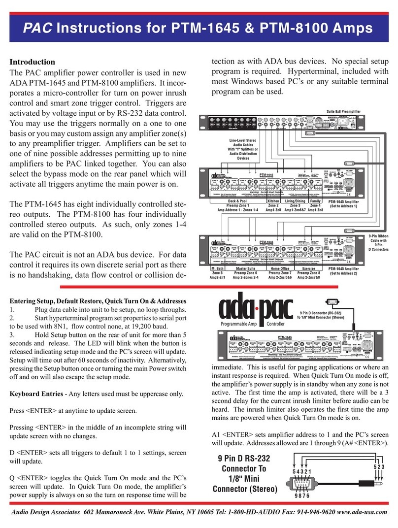
Audio Design Associates
Audio Design Associates ada-pac PTM-1645 User manual
Audio Design Associates
Audio Design Associates ADA 6.1 User manual

Audio Design Associates
Audio Design Associates Cinema Reference Mach II PTM-6150 User manual

Audio Design Associates
Audio Design Associates Suite 7.1 HD User manual
