manuals.online logo
Brands
  1. Home
  2. •
  3. Brands
  4. •
  5. Yamaha
  6. •
  7. Amplifier
  8. •
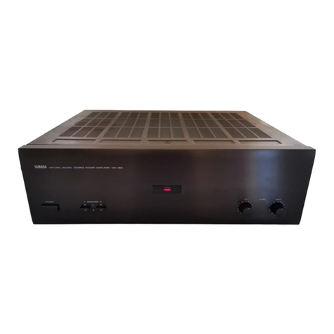
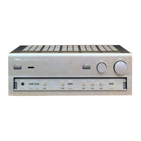
  9. Yamaha A-760II User manual

Yamaha A-760II User manual

Other Yamaha Amplifier manuals

Yamaha A-S3000 User manual

Yamaha

Yamaha A-S3000 User manual

Yamaha DSP-A970 User manual

Yamaha

Yamaha DSP-A970 User manual

Yamaha RX V565 User manual

Yamaha

Yamaha RX V565 User manual

Yamaha AX-900 User manual

Yamaha

Yamaha AX-900 User manual

Yamaha DSP-A492 User manual

Yamaha

Yamaha DSP-A492 User manual

Yamaha WXA-50 User manual

Yamaha

Yamaha WXA-50 User manual

Yamaha AP-U70 User manual

Yamaha

Yamaha AP-U70 User manual

Yamaha A-S700 - Amplifier User manual

Yamaha

Yamaha A-S700 - Amplifier User manual

Yamaha P2100 User manual

Yamaha

Yamaha P2100 User manual

Yamaha AX-400/U Installation guide

Yamaha

Yamaha AX-400/U Installation guide

Yamaha DSP-A2 User manual

Yamaha

Yamaha DSP-A2 User manual

Yamaha A-S500 User manual

Yamaha

Yamaha A-S500 User manual

Yamaha MX-600/L User manual

Yamaha

Yamaha MX-600/L User manual

Yamaha PC4800N User manual

Yamaha

Yamaha PC4800N User manual

Yamaha M-35 User manual

Yamaha

Yamaha M-35 User manual

Yamaha PC2002 User manual

Yamaha

Yamaha PC2002 User manual

Yamaha CX-1000 User manual

Yamaha

Yamaha CX-1000 User manual

Yamaha P2160 User manual

Yamaha

Yamaha P2160 User manual

Yamaha AX-9 User manual

Yamaha

Yamaha AX-9 User manual

Yamaha MX-A5200 User manual

Yamaha

Yamaha MX-A5200 User manual

Yamaha HA8 User manual

Yamaha

Yamaha HA8 User manual

Yamaha C-80 User manual

Yamaha

Yamaha C-80 User manual

Yamaha MX-70 User manual

Yamaha

Yamaha MX-70 User manual

Yamaha AV-75PRO User manual

Yamaha

Yamaha AV-75PRO User manual

Popular Amplifier manuals by other brands

Magnat Audio EDITION FOUR Owner's manual/warranty document

Magnat Audio

Magnat Audio EDITION FOUR Owner's manual/warranty document

Inter-m PA-2000A Operation manual

Inter-m

Inter-m PA-2000A Operation manual

Peavey TNT 150 user guide

Peavey

Peavey TNT 150 user guide

Bosch LBB 1903/10 Installation and user instructions

Bosch

Bosch LBB 1903/10 Installation and user instructions

Avocent Emerge DA1200D Installer/user guide

Avocent

Avocent Emerge DA1200D Installer/user guide

Redgum RGi35 operating instructions

Redgum

Redgum RGi35 operating instructions

Cambridge Audio AXA25 user manual

Cambridge Audio

Cambridge Audio AXA25 user manual

Alpine MRP-M200 owner's manual

Alpine

Alpine MRP-M200 owner's manual

Technical Pro H1502UrBT user manual

Technical Pro

Technical Pro H1502UrBT user manual

FMS EMGZ307 operating manual

FMS

FMS EMGZ307 operating manual

Racal Instruments 5601 user manual

Racal Instruments

Racal Instruments 5601 user manual

Valcom V-1094A Technical specifications

Valcom

Valcom V-1094A Technical specifications

Cambridge Audio 851D user manual

Cambridge Audio

Cambridge Audio 851D user manual

QSC 3800 Specifications

QSC

QSC 3800 Specifications

NAD C300 owner's manual

NAD

NAD C300 owner's manual

Rotel RMB-1077 owner's manual

Rotel

Rotel RMB-1077 owner's manual

Peavey Monitor 300 Series operating guide

Peavey

Peavey Monitor 300 Series operating guide

Crown XTi 1002 Specifications

Crown

Crown XTi 1002 Specifications

manuals.online logo
manuals.online logoBrands
  • About & Mission
  • Contact us
  • Privacy Policy
  • Terms and Conditions

Copyright 2025 Manuals.Online. All Rights Reserved.

sE EO I
L
I
F
I
E
fi3
~
TE
q~h
TE
DAM
)
SE
VICE MAN
. FRONT
PANEL
1
,
-
'
-
~
\
""'
,
-
:~-:
;
~
::
;
~
~'
; •
-.
-
=.-"
~-
,.- ", Q
.-
,~
:
~
:Q
· l,_/ ' . . ~
_
. _ . ...
~
.'
.
,T
.~
~
,
-
I
·
(\
. "
1'1"
"
·
· ..
.
-.
. ' 1" , : I
Power Switch
Treble
Control
f)
Listening Level
Monitor
..
High
Filter
Main
Direct
Switch
Loudness
Control
Disc Switch Balance
Control
Muting
Switch
a.
Mode
Control
(1) Volume
Control
Phono
Select
or
Speaker
Switch Rec
Out
Sele
ctor
o
Phones
Jack
f)
Input
Selector
Bass
Control
.
CONTENTS
Rear
panel.
. . . • . . . . . . . . . . . . . . . . . . . . . . . . • . . . . . . . . . . . . . . . . . . . . . . . . . . • . . . . . . . . . . . . . 1
Names of
the
Parts 2
Disassembly
Instructions
. . . . . . . . . . . . • . . . . . . . . . . . . . . . . . . . . . . . . . . . . • . . . . . . . . . . . . . . . .
..
3
Specifications
. . . . . . . . .
..
. . . . . . . . . . • . . . . . . . . . . . . . . . . . . . . . . . . • • . . • . . . . . . . • . . . . . . . . 5
Adjustm
ents . .
.. ..
. . . . . . . .
..
. . . . . . . . . . . . . .
...
. . .
..
. . . . . • . . • . . . . . . . . . . . . . • . . . . . . . 6
Block Diagram . . . . . . . . . . . . . . . . . . . . . . . . . . . . . . . . . . . . . . . . . . . . . . . . . . . . . . . . . . . • . . . . . • . 7
Printed
Circuit
Layout.
. . . . . . . . . . . . . . . . . . . . . . . . . . . . . . . . . . . . . . . . . . . . . . . . . . • . . . . . • . . . . 7
Printed
Circuit Board/Wiring _ . . . . . • . . . . . . . . . .
..
9
Complete
Circuit Diagram 10
3
~
SINCE 1887 •
YA
MAH
I004458 I " NIPPON GAKKI CO.. LTO. HAMAMATSU, JAPAN
.
82
.
3.2
.65K f {
~
Pnnted rn Japan,
•
••
•••
--
-•• • •• •
--
-
A-760
n
.REA
R
PANEL
Tr r
I,
'
l:J
m c-..
. -="I
CI
LSZ.
1
'--
---
---
-1 r-
fJ UTlJH
))
ftll
FlhIM
'llß(
sot"
W5.SIE
BOT
Il).!
~r
OH
AlTEHfOI
~"
PIlS
EPl
IVER
us\I'$..LA. usM;nU :T){M
AU
·
OESSClJS
Cl:
L
IAWl
L
••
• • • •
~~i'ii1J
@
:
ciI
r:r
Flt
(Jl &OJ(KAl
ARlOO
MJt OPOSf
r
~
APPt
lUU
L-
---' I-r- - - -
----'@
U.S.A and Canadian Models
Gnd
ter
minal o Tape 1
,2
record
/playback
[acks
Phono
input
jacks
Speaker
A. B ter minals
Tuner
input
jacks o AC
outlets
o Aux input jacks o Power
cord
r ]
<..sz
""
~I
OYAMA
HJI
~
~
~~
~
eaowerrs @]
---
IItPPOllaW
CQ.UD.
Austr
alian and British Models
...
....
O
Y
AM
A
HA
~
~
~
~
s
~
:.oo
Wll.
ns
lQl
NIPPONGAUl ce,
lT'D.
European Model
OYA
M
A
HA
~
~
HO 12'0 2::.>0»4 0 1IQ.1'S
3:C""",rrs :.a /OO Hl
-c,
ro
Jt
GUJtI C
D..UD.
•••
•
••
General Model
1-------------------
--------------
--
A-760
1I
• NAME OF
THE
PA TS
Internal Top View
U.S.A and Canadian Model
AC
outlet
Muting
switch
Power cord Disk switch
Power transformer
il
Main
Direct
switch
Main board 2 (
NA07
861·2) Tone
control
board 1 (NA07859-1)
Heat sink Main board 4 (NA07861-4)
Power transistor Main board 5 (NA07861-5)
Main board 1
(NA07
86
1·1l
Power switch
Function board
(NA07857)
Primary board 1
Tone control board 3
(NA07859-3l
Primary board 2
Tone
control
board 2
(NA07859
-2)
---------
-------------------------2
DISAS
SEMBLY
INSTRUCTIONS
1.
Remo
ving the top cover
Remove screws
CD
and 0 on each side, per
photo
1 and remove
the
top
cover by pulling back and
lifting up,
4. Removing
the
rear panel
a) Remove
the
top
cover (step 1).
b) Remove
the
bottom
cover (step 2).
c) Remove screws
CD
~
@ . The
be taken off. cover can then
2. Removing
the
bo
tt
om cover
Flip
the
A-760II over and remove screws
CI)
~
®
in
phot
o 2;
then
remove
the
bottom
cover.
Photo
2
3. Removing th e
fron
t panel
a) Remove
the
top
cover (step 1).
b) Remove
the
bottom
cover (step 2).
c) Loosen
the
Speaker, Rec
Out
and Input knobs with
a 1.5 mm allen
wrench.
PuHeach
knob
off its shaft.
d) Disconnect
the
wires from
the
Power, Main Direct,
Disc and Muting switches being carefule
not
to
brake
them.
e) Remove screws
CD
and 0 in
photo
3 and remove
the
front
panel by pulling forward.
Photo 4
5. Removing
the
function
board
a) Remove
the
top
cover (step 1).
b) Detach
the
various
cords
and connec
to
rs; then
detach the flexible wire fro m each switch with a
screwdriver. (Fig. 1)
c)
Take
out
screws @
~
@
photo
4 to
remov
e
the
function
board.
Fig.l
6. Removing
tone
control
boards
1, 2, and 3, main
boards
4 and 5 and
the
power
switch
a) Remove
the
top
cover,
bottorn
cover, and
front
panel (steps
1,2,3).
b) Pull off the Bass,
Treb
le, Loudness, Balance and
Volurne
controls.
c)
Tone
control boards 2
and
3 can be removed by
taking
out
nut
®
and
screws G)
~
® in p
hoto
5,
d)
Tone
control
board
1 can be rernoved by taking
out
screws (j) and ® and
nuts
®
~
® in ph
oto
5.
e) Main board 4 is rem oved by ta king
out
screws
®and @
and
pulling
off
the
Lis
tening
Level
Monitor
knob
in
pho
to 5.
f) The power switch can be removed by removing
screws @
and
@ in
phot
o 5.
g) Main board 5 can be rernoved by pu lling out the
phone
iack fastener ® in ph oto 5 in th e direction
of
the
arrow.
3----------
----------
---------------
7.
Rem
oving main board 1
and
the
heat
sink
a) Remove
the
top
and
bottom
covers,
b)
Remov
e
the
function
board
(step 5).
c) Desolder
power
transistors
TR335
-
TR338.
d) Take
out
main
board
1 by removing screws
CD
-
®in
photo
6.
e)
Detach
connectors
® - @ in
photo
6.
f) Remove
the
heat
sink by
taking
out
screws ®-
® in
photo
6.
*Make sure
that
transistors
TR321
and
TR322
are
correctly
connected
to
the
heat
sink
for
proper
heat
dissipation,
Photo 6
A-760
II
8. Removing
the
power
tran
sform
er
and
pr imary
boards
1 and 2
a) Remove
the
top
cover
(step 1).
b) Remove
the
primary
board
wiring.
c)
Take
out
screw
CD
in
photo
7 and release pr ima ry
boards 1
and
2
from
board
fasteners ®
and
® .
d) Remove
the
power
transformer
cover
by
taking
out
screws ®- ®in
photo
7.
e)
Take
out
screws
CD
-
8)
in
photo
8 to remove
the
power
transformer
.
Photo 8
-------
--------------------------
--4
.SPECIFICAT
IONS
Minimum RMS Output Power Signal-to-NoiseRatio (NEW IHF)
8 ohms, 20 to
20,
OOOHz (Main Direet ON) Phono MM _ _. _ 74.5 dB
0.005% THD 80 W + 80 W Phono MC .
__
78 dB
8
ohins,
1 kHz 0.002% Aux/Tape/Tuner 85 dB (Main Direct
THD
. 80 W +
80W
ON)
4 ohms elipping power Residual Noise
. 1
k
H
~
0.5%
THD
150 W + 150 W (lHF A Network) .
__
. . . . 65 p.V
Total Harmonie Distortion
Input
Equivalent Noise
(20 Hz to 20 kHz) Phono MM - 138 dBV
Phono
MM
·to Ree Out Phono MC _ - 142 dBV
(5
Vou
tput! 0.003% Filter Charaeteristics
Phono MC to Ree Out High 10 kHz, 12
dB/o
ct.
(5 V output] 0.006% Channel Separation
Aux/T
ape
/Tu
ner to Sp (1 kHz, vol.
-30
dB, Shorted)
Out
(40
W, Main Direet Aux, Tuner to Sp Out 70 dB
ON) . : ' 0.005% Phono MM to Sp Out
..
. . 70 dB
IM Distortion Ratio (60 Hz : 7 kHz =4 : 1) Phono MC to Sp
Out.
. . . . 70 dB
Aux/Tape/Tuner to Sp Out Continuous LoudnessContral
8 ohms, 80W . . . . . . . . . 0.002% (Level-Related Equalization)
8 ohrns, 1 W 0.01% Max. Attenuation 20 dB at 1 kHz
Power Bandwidth (Main Direet
ON)
Audio Muting _ . .
-20
dB
(8 ohms, 40 W, 0.02% Gain Traeking Error
THD)
. . : , 10 Hz to 100 kHz (0 to
-60
dB) _. . 2 dB
Damping Faetor Headphone Output/lmpedance
(8 ohrns, 1 kHz) . Better than 65 (0.01%
THD)
0.72 V/8 ohms
Frequency
Response
6.8 V/ 100
ohm
s
(
Au
x
t
~a
p
e
/
T
u
n
e
r
to Sp Power Supplies. . . . . . . . . . . 120 V. 60 Hz (U,C)
Out, 8 ohms) .
..
. . 1 Hz to 100 kHz 220 V. 50 Hz (G,W)
," (+0,
-2
dB)
240
V, 50 Hz
(A,
B)
RIAA
Deviation 110/1 2
0/
22
0/
240 V,
Phono
MM
. ± 0.2 dB 50/60 Hz (R )
Phono MC . ±
0.3
dB Power Consumption . , . . . . . 350 W/
850
VA (Cl
Input Sensitivity/lmpedance 350 W (U, R)
Phono MM . 2.5
mV
/47 k ahms 520 IN (A, G, B, W)
Phono'MC . 160 JJV/ 100 ohms AC Outlets
Aux/Tape/Tuner . 150
mV
/47
kohrns Switehed x 2 . 100 W max total
Maximum Input Level (1 kHz) Unswitched
xl
. . . . . . . .
200
W max
Phono MM . 180 mV RMS Dimensions (W x H x D)
...
. 435 x 112 x 365 mm
Phono MC . 10 mV RMS (17-1/8" x 4-7/1 6" x
Tone Control Charaeteristies 14
-3/
8" )
Ba
ss
. ± 10 dB at 20 Hz Weight . . 9.1 kg (20 lbs., 7 oz.)
Tr
eble .
±lOdBat20kHz
Turnover Frequeneies Specifieations subjeet to change without notiee.
Bass . 500 Hz
Treble . 3.5 kHz U :
USA.
Model
Output Level/lmpedance C : Canadian Model
Ree Out . 150
mV
/270
ohms R : General Model
Signal-to-Noise Ratio A : Au stralian Mod el
(I HF A Network, Input B : British Model
Shorted) G : European
Mod
el
Phono M
(5
mV)
....
. 92 dB W : West Ger
many
Model
Phono MC (500 JN)
..
76 dB
Aux/Tape/T
uner 106 dB (Main Direct
ON)
5--------------------------------
A-760
II
GENERAL A JUSTMENTS
Before adjustment
• Make sure that t he AC line is ± 10%
• Wait 5 minutes aft er power-on
to
stabilize amplifier
operation
Test
Step Adjustment
Conditions
Loeation
Test
Point Value
Equipment
:
Main B
+"B-
Between chassis ground Digital
Main
board
1
voltage ad- No load and P1 terminal of pri- 47.5±O.3V
voltmeter
1
VR303
justment
mary
board
(test er)
Between P1 and
TP3
of
the
primary
board 1.2V±O.1V
Photo
coup
-Minimum volume, (if
out
of ranqe,
turn
to VR501 and
VR303
(2
.0V±0
.1V
same as
2 ler
cur
r
ent
no load and
adjust
B+,
B-
and P1 - TP3 =FEMKO, above
che
ck* for
rated
voltages) DEMKO)
Main
board
1.
Idling
TP3
-
TP4
(L), same as
3 Minimum volume VR301 (L ch) ,
6.6
:g mV
adjustment
TP1 - TP2 (R) abo ve
VR302
(R ch)
Output
off
- L. R
within
same as
4 Minimum volume Speaker
terminals
set check o± 30 mV above
* It is
not
necessary to
check
the
photo
-coupler
current
of
step
2
except
when
replacing
the
photo
-coupler,
Also, perform steps 1 and 2
simultaneously
(with
two
digital voltmeters).
ADJUSTMENT LOCATION DIAGRAM Main c.
board
1
D
VR301 (L ) VR30
2lRl
TP3 @ @
Primary c.
board
1 c
00
TPI
TP4 c
c TP2
c
VR501 o0
0501 0
10
TR501 TP5
o
D o
• TP7
rp6
c
o
Pl
mTP3
FRONT
Primary c.
board
2
-------
--------
---------
-----------
- -
-6
A-7601I
- J
BL
CK DIAGR
AM
/.-
ZDR
oe SER....O
TONE AMP HIGH POWER ..tMP
REC INPUT DISC MODE FILTER LOUDNESS
PHONO MUTING 1\ \
BALAN
CE \\
\ } {\
' , BASS TREBLE \
~ - -
---
-
-
----
-
-
-
---
----
------
-
-~
VOLUME
AUX
TUNER
@-----~---
t___1
~H
EA
DP
HO
N
E
PB '
TAPE PB 2
TAPE
t-
- -
--<
7"'i
:
~
SPEAKER
REC 1 "'ROf
fer
tON ;
~
~
~
~
~
R
REC 2
~
----
.-
--
-'
,
POWER SWITCH
-0
':-0-
+47.5
V
constant
A
CI
N
--47.5
V
constan
t
. PRIN
lE
D CIRCUIT BOARD PAnERN-SIDE COMPONENTS LAYOUT
Primary c. board (Australian, British and European Models)
~
' ,
~U
TR
~
O
I
..
n J
J
~
,....---------,~I===I=
I=
I==
7----------------------------------
8-----
---------------
----------
---------
Lpaeoq ":l
I
O
J
~
U
O:l
auoj,
e ...
PRINTED CIRCUIT BOARD PATTERN-SIDE COMPONENTS
LAY
OUT
Primary c. board (U. S. A and Canadian Models) Primary c. board (General M
odell
Function circuit board Main e, board 5
Tone
control c. board 3 Tone control c. board 2