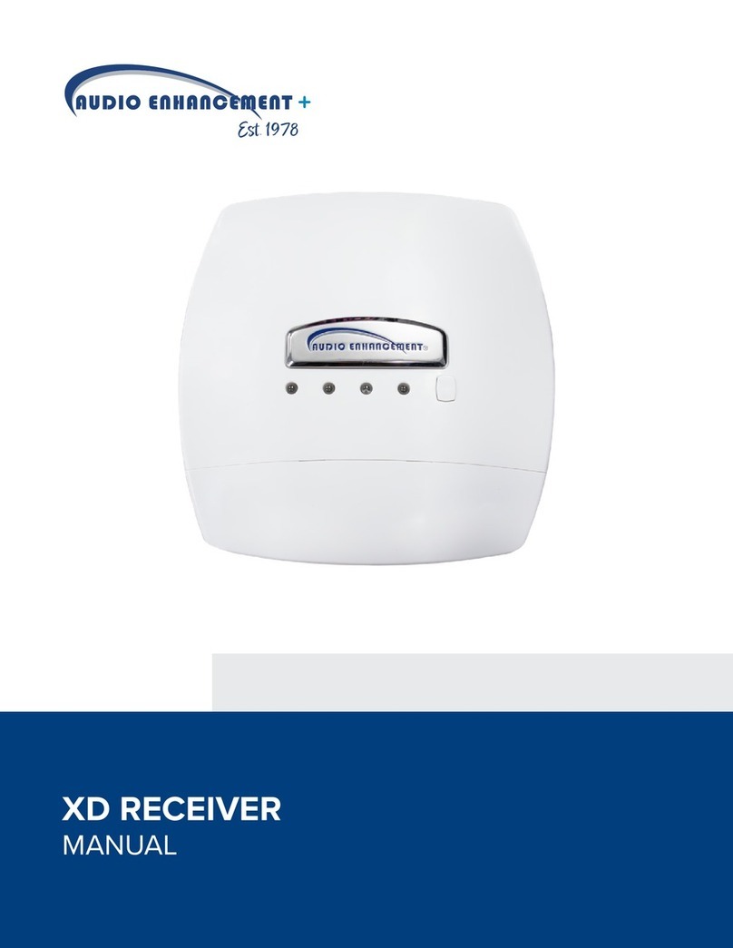
Audio enhancement K-SRC14 User manual

1
Rev.2.10
9858 S. Audio Drive, West Jordan, UT 84081 • Phone 1.800.383.9362 • AudioEnhancement.com
XD Wireless Receiver
K-SRC14 | 1.9 GHz

2
Rev.2.10
FCC CAUTION
Changes or modifications not expressly approved by the party responsible for compliance could void the
user’s authority to operate the equipment.
This device complies with part 15 of the FCC Rules. Operation is subject to the following two conditions: (1)
This device may not cause harmful interference, and (2) this device must accept any interference received,
including interference that may cause undesired operation.
Note: This equipment has been tested and found to comply with the limits for a Class A digital device,
pursuant to part 15 of the FCC Rules. These limits are designed to provide reasonable protection against
harmful interference when the equipment is operated in a commercial environment. This equipment
generates, uses, and can radiate radio frequency energy, but if not installed and used in accordance with
the instruction manual, may cause harmful interference to radio communications. Operation of this
equipment in a residential area is likely to cause harmful interference, in which case the user will be required
to correct the interference at his own expense.
Compliance with FCC requirement 15.407(c)
Data transmission is always initiated by software, which is passed down through the MAC, through the
digital and analog baseband, and finally to the RF chip. Several special packets are initiated by the MAC.
These are the only ways the digital baseband portion will turn on the RF transmitter, which it then turns off at
the end of the packet. Therefore, the transmitter will be on only while one of the aforementioned packets is
being transmitted. In other words, this device automatically discontinues transmission in case of either
absence of information to transmit or operational failure.
Radio Frequency (RF) Exposure Warning
This equipment complies with FCC radiation exposure limits set forth for an uncontrolled environment and
meets the FCC radio frequency (RF) Exposure Guidelines. This equipment should be installed and operated
keeping the radiator at least 20cm or more away from person’s body (excluding extremities: hands, wrists,
feet and ankles).
MEDICAL:
Consult the manufacturer of any personal medical devices, such as pacemakers, to determine if they are
adequately shielded from external RF (radio frequency) energy. The unit operates in the frequency range of
1.92 GHz to 1.93 GHz.
Do not use the unit in health care facilities if any regulations posted in the area instruct you not to do so.
Hospitals or health care facilities may be using equipment that could be sensitive to external RF (radio
frequency) energy.
Notice
FCC ID can be found on the bottom of the units.

3
Rev.2.10
Safety precautions
WARNING:
- The main plug or an appliance coupler shall remain readily operable.
- To pre v ent inj u ry, thi s ap p ara t us must be sec u rel y at t ach e d t o th e fl o or/ w all in a cco rdan ce w ith the
installation instructions.
- The connections should comply with local electrical code.
- The installation shall be carried out in accordance with all applicable installation rules.
- To red u ce t he r isk of f ire or e lec t ric sho c k, d o n ot e xpos e t h is a ppa r atu s to rai n or moisture.
- The apparatus should not be exposed to dripping or splashing and that no objects filled with liquids,
such as vases.
- All work related to the installation of this product should be made by qualified service personnel or
system installers.
- This product has no power switch. When turning off the power, disconnect the LAN cable from this
product.
CAUTION:
Before attempting to connect or operate this product, please read the label on the bottom.
The model number and serial number of this product may be found on the surface of the unit.
You should note the model number and serial number of this unit in the space provided and retain this
book as a permanent record of your purchase to aid identification in the event of theft.
Model No.
Serial No.

4
Rev.2.10
CONTENTS
Important safety instructions ....................................................................................................... 5
Major operating controls and their functions ............................................................................... 6
Pairing registration of the microphone to a receiver ................................................................... 9
Classroom Audio ....................................................................................................................... 10
Alert message and sound at E2 ................................................................................................ 10
Link error between WAP and the receivers .............................................................................. 10
Functions .................................................................................................................................. 11
LED lighting indication .............................................................................................................. 13
DIP switch setting ..................................................................................................................... 15
Connections .............................................................................................................................. 18
Precautions for installation ........................................................................................................ 22
Installation. ................................................................................................................................ 23
Serial communication command ............................................................................................... 27
Troubleshooting ........................................................................................................................ 33
Specifications ............................................................................................................................ 34
Accessories............................................................................................................................... 35

5
Rev.2.10
Important safety instructions
1) Read these instructions.
2) Keep these instructions.
3) Heed all warnings.
4) Follow all instructions.
5) Do not use this apparatus near water.
6) Clean only with dry cloth.
7) Do not block any ventilation openings. Install in accordance with the manufacturer's instructions.
8) Do not install near any heat sources such as radiators, heat registers, stoves, or other apparatus (including
amplifiers) that produce heat.
9) Protect the power cord from being walked on or pinched, particularly at plugs, convenience receptacles, and
the point where they exit from the apparatus.
10) Only use attachments/accessories specified by the manufacturer.
11) Use only with the cart, stand, tripod, bracket, or table specified by the manufacturer, or sold with the
apparatus. When a cart is used, use caution when moving the cart/apparatus combination to avoid injury from
tip-over.
12) Unplug this apparatus during lightning storms or when unused for long periods of time.
13) Refer all servicing to qualified service personnel. Servicing is required when the apparatus has been
damaged in any way, such as if a power-supply cord or plug is damaged, liquid has been spilled or objects
have fallen into the apparatus, the apparatus has been exposed to rain or moisture, does not operate
normally, or has been dropped.
14) Make sure that the wall that the shelf will be attached to is strong enough to support the shelf. If not, it is
necessary for the wall to be reinforced.
15) For safety reasons, do not physically modify the product or any optional equipment.
16) To prevent possible fire or electric shock, do not expose this product to rain or moisture.
17) Follow all warnings and instructions marked on this product.
18) To reduce the risk of electric shock, do not disassemble this product. Only qualified personnel should service
this product. Opening or removing covers may expose you to dangerous voltages or other risks. Incorrect
reassembly can cause electric shock.
19) The product should never be placed near or over a radiator or other heat source.
20) Do not use a microwave oven to dry this product.
21) The product may only be installed and serviced by qualified service personnel.

6
Rev.2.10
Major operating controls and their functions
[1] [LINK] button
Pressing this button will put the receiver into register mode to pair with a microphone.
(This register mode is canceled after 20 seconds)
Refer to operating procedures
(At the time of E2 state, the button operation is invalid)
[2] [POWER] POWER indicator
(Green/Yellow/Red)
This LED lights green when the power is on and this unit can receive signals under normal conditions.
This LED lights as follows to indicate other states:
E2 signal output provided: lights red
Page mute signal received: lights yellow (It glows red when in E2 state)
[3] [MIC1/MIC2] MIC1/MIC2 indicator
This LED lights green when this unit is receiving signals from each microphone under normal conditions.
This LED lights as follows to indicate other states:
E2 signal output provided: lights red
Page mute signal received: lights yellow (It is red indication at the time of E2 state)
E1 signal output provided: lights (300 ms) red
Feedback blocker in operation: lights (5 sec) yellow
[4] [LINK] LINK indicator
This LED lights green during Audio link with the WAP or when a media microphone is paired with the third channel
This LED blinks yellow (500 ms) during pairing registration
This LED lights red when the link connection to the WAP is broken. (DIP switch 2-8 = ON) or system error.
9
8
7
6
5
4
1
2
3
3
10

7
Rev.2.10
[5] Control terminals
8-pin and 7-pin Euro blocks are used.
The following terminals are equipped.
E1 CNT: provides E1 signal * output controlled by K-STD14 (Teacher Microphone).
E2 CNT: provides E2 signal * output controlled by K-STD14.
* Those are available when K-STD14 is used. Settings of E1 and E2 are performed with K-STD14.
E2 ACK: connects acknowledge signals responding to E2 output.
PAGE MUTE: provides “make signal” inputs externally when the paging function is used.
RS-232C: is used to control this unit via communication from an external device.
LINK button: provides “make signal” inputs externally when the external link button is used.
Alert Notification Button: provides “make signal” inputs externally when the external Alert Notification Button is used.
[6] Amplifier interface connector
This connector is used to connect the cable to the amplifier.
A standard CAT5 or CAT5e cable is used to connect to the amplifier.
[7] MIX OUT (unbalanced) connector
The LINE IN connector provides audio output for other media players. Setting the No. 4 of the DIP switch 1 to ON allows the
audio outputs of the microphone MIC1 and MIC2 received by this unit to be provided after mixing with LINE IN. This is an
unbalanced output. A stereo mini plug (φ3.5 mm) is used.
[8] LINE IN connector
This connector is used to provide an audio input from external sources such as a projector or CD. This is a stereo, line level
input, and is internally mixed to a monaural signal. A stereo mini plug (φ3.5 mm) is used.
[9] DIP Switches
Two DIP switches are used.
The settings of this switch are updated when the receiver powers on.
Settings changed while powered on are not updated until the receiver is restarted. (Excluding No.7 of DIP Switch 1)
[10] Screw cover
This screw cover is used when doing the ceiling and wall mounting installation. Open this screw cover and screw on a
mounting plate.

8
Rev.2.10
Operating procedures
1. A standard CAT5 or CAT5e cable is used to connect to the amplifier. Turn on the amplifier.
The POWER LED of the receiver lights green.
2. Power ON the microphone.
[K-STD14]: Press and hold the [PWR/MUTE] button for one second.
[K-SHH14]: Push [TALK] button or flip up the [TALK] switch.
The MIC1 or MIC2 LED indicator of the lights green (depending on a channel to be received.)
3. Adjust the volume of external devices such as an amplifier.
The overall volume is adjusted with the external amplifier or the like. Use volume buttons on the Te ac her Mi cr op ho ne (K-
STD14) to adjust the volume. Adjust the volume of the other microphone or LINE IN by pressing the Select button on the K-
STD14.
4. The LED of the POWER/MIC1/MIC2 indicates the operating state of this unit during operation.
LED
POWER indicator
MIC1/MIC2 indicator
E2 signal output provided*
Lights red
Lights red
(lights green at E2 ACK input provided)
E1 signal output provided*
Lights green
Lights red (for 300 ms)
Page mute signal input provided
Lights yellow
Lights yellow
Microphone volume operated*
Lights green
No light (for 300 ms)
Feedback blocker operated
Lights green
Lights yellow (for 5 sec)
During audio link
Light green
Lights green
* Only applicable when K-STD14 is used
5. The LED of the LINK indicates the operating state of this unit during operation.
During audio link with the WAP
Lights green
During pairing registration
Blinks yellow at 500 ms period
System error
Lights red

9
Rev.2.10
Pairing registration of the microphone to a receiver
When pairing a new microphone to a receiver, follow this procedure.
(Only the Alert Notification Button operates without first pairing the microphone)
1. Press a receiver's [LINK] button, and the receiver is put into registration mode.
When a LINK button is pressed, the LINK LED blinks yellow for 20 seconds (pairing registration mode)
During this time, please use the following instructions to pair your microphones.
2. (a) Tea ch er M ic rop hon e (K-STD14):
Press the [PWR/MUTE] button and [REC] button for one second to register with the receiver.
Teacher Microphone [BATT] indicator lights green and an audible beep will sound through the speakers.
(b) Student Microphone (K-SHH14):
(Please read the operating instructions of the Student Microphone (K-SHH14).
Press the [LINK] button and [TALK] button simultaneously for one second or more to register with the receiver.
Student Microphone [BATT] indicator lights green and an audible beep will sound through the speakers.
(c) Media Channel Microphone:
Repeat directions above to pair a third microphone. This option is only available after two microphones are already paired
to the receiver. [LINK] indicator lights green and an audible beep will sound through the speakers.
1.
[LINK] button
[LINK] button
[PWR/MUTE] button
[REC] button

10
Rev.2.10
Classroom Audio
Teacher Microphone [K-STD14]
1. Pressing the [PWR/MUTE] button for one second or more will power up the microphone.
The microphone can be used in a classroom. (When paired, MIC1 or MIC2 LED indicator lights green on the receiver)
Note:
• Also read the operating instructions of the Teacher Microphone (K-STD14).
Student Microphone [K-SHH14]
2. Pressing the [TALK] button or pushing up the [TALK] switch will turn on the microphone.
The microphone can be used in a classroom. (MIC2 or MIC1 LED indicator lights green on the receiver)
Note:
• Also read the operating instructions of the Student Microphone (K-SHH14).
Alert message and sound at E2
1. Paired mode (Microphone connected to a receiver.)
When a Teacher Microphone is paired to the receiver and the “E2” buttons are pressed simultaneously for 2 seconds or more.
The Teacher Microphone immediately sends an Alert message to the receiver.
(MIC1/POWER/MIC2 indicator: lights red.)
The microphone continues to transmit audio before, during, and after the alert message is sent.
(If the microphone is moved to the "audio mute area*" or the wireless connection breaks location,
the status changes from a paired alert to a non-pair alert.)
Audio mute area: Refer to "Command List [SAA]”
Even when the Tea che r Microphone is off, an alert can be sent by pressing the E2 buttons on the microphone.
If the microphone is able to connect to its paired receiver, it will be in a paired alert state.
(If the microphone can not connect to its paired receiver, it will be in a non-pair state)
2. Non-paired mode. (Microphone isn't connected to a receiver.)
If the Microphone is not paired to the receiver and the “E2” buttons are pressed for 2 seconds or more.
#1: The microphone uses the ALL command to search for nearby receivers.
#2: The five closest receivers will return a signal to the microphone, helping software plot the E2 alert’s location on.
#3: The Microphone will repeat #2 every 30 seconds until the microphone is turned OFF.
(MIC1/POWER/MIC2 indicator: there is no change.)
*The microphone in non-paired mode never transmits audio.
*Alerts from the Alert Notification Button will only be sent alert information
Link error between WAP and the receivers
If a link error occurs between the WAP and receiver, the receiver reboots every 30 seconds in order to restore the
link between WAP and the receiver automatically, (LINK between WAP and the receiver usually succeeds after
the receiver reboots a few times.) When the link between the WAP and the receiver is not established, the
receiver reboots every 30 seconds continuously, even during use of the microphone.

11
Rev.2.10
Functions
● Microphone override function
This is a function where the audio level of LINE IN automatically lowers when the audio input of the microphone MIC1 or
microphone MIC2 is provided. The attenuation of the audio level is –12 dB.
When the audio input of the MIC1 or MIC2 is no longer provided, the volume of LINE IN automatically returns to the previous
level.
● Paging mute function
This is a function where the audio outputs of the MIC1, MIC2, and mixing output of this unit are muted by closing the PAGE
MUTE terminal.
This function is specified with the control terminal or RS-232C. This function is set to OFF at default settings.
● Tone function
This is a function where the operation sound output is provided from the MIX OUT connector when the volume button is
operated with the optional microphone, K-STD14. The operation sound is generated twice at the maximum and minimum
volumes.
The level of the operation sound can be set to HIGH or LOW with the DIP switch. The level is set to LOW at default settings.
This function is specified with the DIP switch. This function is set to OFF at default settings.
● Microphone / line mixing function
This function is designed to assign the microphones, MIC1 and MIC2, to the mixing out, and two signals will be mixed with the
mixing out.
● Remote volume function
This is a function where the volume of this unit cannot be adjusted with the volume button of the optional microphone, K-
STD14.
This function is used when external devices are controlled with the volume button through the use of the communication
control function of this unit.
This function is specified with the DIP switch. The volume can be controlled with the microphone at default settings.
● Mixing output attenuator function
Setting the mixing output attenuator to ON provides attenuation in the mixing output by 10dB.
This function is useful when a device with high input sensitivity is connected.
This function is specified with the DIP switch. The output is set to –10dB at default settings.
■ About the feedback blocker
This is a function where the feedback loop generated when the microphone and speaker approach each other is reduced.
An integrated filter is automatically selected according to the generated audio frequency, and reduces the uncomfortable
feedback loop.
This function is specified with the DIP switch. This function is set to OFF at default settings.
Note: This function is simplified, and cannot fully remove the feedback loop. When the feedback loop is extremely large, this
function will work to mute all the audio outputs of this unit.

12
Rev.2.10
● E1 CNT, E2 CNT function
These functions are available when the K-STD14 microphone is used. When E1 or E2 is controlled with the microphone,
control signals are provided from the E1 CNT or E2 CNT terminal of this unit. Selection between E1 and E2 is made at the
microphone side.
E1: Default setting is Open
Press the button [REC] on the Teacher microphone to select the closed state of 300 ms.
E2: Default setting is Open
Press both side [E2] buttons simultaneously on the Teacher Microphone for 2 seconds or more or press the alert button to
select the close state.
● E2 ACK function
When “make signal” inputs are provided to E2 ACK of the control terminals during E2 operation, the MIC1 or MIC2 LED
indicator of this unit turn from red to green to indicate that the E2 ACK signal is received.
When the E2 control input has not been provided from the microphone for 3 minutes after turning off the power of the
microphone, the E2 state ends, the MIC1 or MIC2 LED indicator indicates the receiving state, and the operation LED turns
from red to green to indicate the operating state.

13
Rev.2.10
LED lighting indication
LED lighting indication 1 [POWER/MIC1/MIC2]
The three LEDs of this unit act as a status indicator, indicating signal reception. Those LEDs indicate the
operating states as shown in the table. Furthermore, the priority order of the indications is dependent on operating
states.
*1 E1 signal outputs and operating the volume button are only available with the K-STD14 microphone.
E2 outputs from the Teacher Microphone or alert button.
*2 The indicator lights green again three minutes after the E2 signal is turned off with the microphone, K-STD14.
After three minutes elapsed since the alert button is pressed, the receiver will turn off the red LED lights.
Memo:
When a microphone moves to the audio mute area*, the MIC1 or MIC2 LED turns off.
*Audio mute area: Refer to "Command List [SAA]”
With WAP (VPS*) System:
If the REC button is pressed, the LED display will change at the direction of the computer.
*VPS: View Pass Server
Indication
priority
Operating state
LED indication
MIC1
POWER
MIC2
1
(highest)
E2 signal output
provided*1
Red
(Lighting green at E2
ACK input provided)
Red *2
(Lighting green
at Power OFF)
Red
(Lighting green at E2
ACK input provided)
2
Paging mute signal input
Yellow
Yellow
Yellow
3
E1 signal output
provided*1
Red
(Lighting for 300 ms)
Green
Red
(Lighting for 300ms)
4
Microphone volume
button operated*1
No lighting
(No lighting for 300 ms at
operating volume button)
Green
No lighting
(No lighting for 300ms at
operating volume
button)
5
Feedback blocker
operated
Yellow
(Lighting for 5 sec)
Green
Yellow
(Lighting for 5s)
6
During Audio link
Green
Green
Green
7
(lowest)
Power ON
No lighting
Green
No lighting

14
Rev.2.10
LED Indication 2 [LINK LED]
When a LINK key is pressed, the LINK LED blinks yellow for 20 sec (pairing registration mode)
・LED color will change according to priority. Shown below:
Without WAP system: LINK LED is normally off.
* If there is no special mention, when a function is completed or time passed, the LED state is restored to its original status.
Status
LED indication
LINK
It has been unable to register with the
WAP or System error
Red
In pairing registration
Blink yellow at 500 ms period (for
20 seconds)
During Audio link with the WAP
Green
When linked with a third microphone
Green
Power ON
No light

15
Rev.2.10
DIP switch setting
switch
No
Name
Function
Off
On
Switch1
1
MIC OVERRIDE
Selection of microphone override function
Deactivated
Activated*
2
TONE ON/OFF
Selection of tone signal from this unit at
operating volume button of K-STD14
Tone OFF
Tone ON*
3
Tone Level H-L
Selection of tone signal (2 levels) at operating
volume button
Low level*
High level
4
MIC/LINE MIX
Microphone/Line Mixing
Selection of whether to mix the microphones
MIC1 and MIC2 to the mixing output (Line Out)
Mixing
deactivated
Mixing
activated*
5
F/B BLOCKER
Feedback Blocker setting
Selection of feedback blocker function
Feedback
blocker
deactivated*
Feedback
blocker
activated
6
RMT VOL
Remote Volume setting
By selecting the remote volume function,
normal mic buttons will be reassigned. When
this switch is set to ON, the volume control of
this unit using the volume button of K-STD14
will be deactivated.
This setting is intended to control an external
device using the volume button of K-STD14
through the serial communication command.
Mic buttons
normal*
(as labeled)
Mic buttons
reassigned
7
Mix OUT-ATN
Attenuation of audio output of the mixing
output (–10 dB)
ATT
deactivated
ATT effective*
8
Tx Pwr Normal/Hi
Selection of transmission output control
NORMAL*
HIGH
Switch2
1
CH3 Vol Line/Mic
Allows the teacher microphone to control
volume for the media channel
Deactivated
Activated
2
AP GROUP bit5
3
AP GROUP bit4
4
AP GROUP bit3
AP Group ID setting
0-127 of Group ID
5
AP GROUP bit2
6
AP GROUP bit1
7
AP GROUP bit0
8
WAP
AP connect
Off*
AP connect
on
*default setting
Default setting
Switch1
Switch2

16
Rev.2.10
Note:
The settings of these switches are updated when the receiver boots up.
Settings changed while powered on are not updated until the receiver is restarted. (Excluding No.7 of DIP Switch 1)
Dip switch2-8[ON]:
If the RCV disconnects from the WAP, the RCV will reboot automatically and try to reconnect with the WAP.
No. 1 to 7 of DIP switch 2 are used for selection of group ID.
(It is used at the time of installation of WAP and a receiver.)
Switch2 Group ID Setting
Group
ID
AP GROUP bit6
AP GROUP bit5
AP GROUP bit4
AP GROUP bit3
AP GROUP bit2
AP GROUP bit1
AP GROUP bit0
Unused
1
OFF
OFF
OFF
OFF
OFF
OFF
ON
-
2
OFF
OFF
OFF
OFF
OFF
ON
OFF
-
3
OFF
OFF
OFF
OFF
OFF
ON
ON
-
4
OFF
OFF
OFF
OFF
ON
OFF
OFF
-
5
OFF
OFF
OFF
OFF
ON
OFF
ON
-
6
OFF
OFF
OFF
OFF
ON
ON
OFF
-
7
OFF
OFF
OFF
OFF
ON
ON
ON
-
8
OFF
OFF
OFF
ON
OFF
OFF
OFF
-
9
OFF
OFF
OFF
ON
OFF
OFF
ON
-
10
OFF
OFF
OFF
ON
OFF
ON
OFF
-
11
OFF
OFF
OFF
ON
OFF
ON
ON
-
12
OFF
OFF
OFF
ON
ON
OFF
OFF
-
13
OFF
OFF
OFF
ON
ON
OFF
ON
-
14
OFF
OFF
OFF
ON
ON
ON
OFF
-
15
OFF
OFF
OFF
ON
ON
ON
ON
-
16
OFF
OFF
ON
OFF
OFF
OFF
OFF
-
17
OFF
OFF
ON
OFF
OFF
OFF
ON
-
18
OFF
OFF
ON
OFF
OFF
ON
OFF
-
19
OFF
OFF
ON
OFF
OFF
ON
ON
-
20
OFF
OFF
ON
OFF
ON
OFF
OFF
-
21
OFF
OFF
ON
OFF
ON
OFF
ON
-
22
OFF
OFF
ON
OFF
ON
ON
OFF
-
23
OFF
OFF
ON
OFF
ON
ON
ON
-
24
OFF
OFF
ON
ON
OFF
OFF
OFF
-
25
OFF
OFF
ON
ON
OFF
OFF
ON
-
26
OFF
OFF
ON
ON
OFF
ON
OFF
-
27
OFF
OFF
ON
ON
OFF
ON
ON
-
28
OFF
OFF
ON
ON
ON
OFF
OFF
-
29
OFF
OFF
ON
ON
ON
OFF
ON
-
30
OFF
OFF
ON
ON
ON
ON
OFF
-
31
OFF
OFF
ON
ON
ON
ON
ON
-
32
OFF
ON
OFF
OFF
OFF
OFF
OFF
-
33
OFF
ON
OFF
OFF
OFF
OFF
ON
-
34
OFF
ON
OFF
OFF
OFF
ON
OFF
-
35
OFF
ON
OFF
OFF
OFF
ON
ON
-
36
OFF
ON
OFF
OFF
ON
OFF
OFF
-
37
OFF
ON
OFF
OFF
ON
OFF
ON
-
38
OFF
ON
OFF
OFF
ON
ON
OFF
-
39
OFF
ON
OFF
OFF
ON
ON
ON
-
40
OFF
ON
OFF
ON
OFF
OFF
OFF
-
41
OFF
ON
OFF
ON
OFF
OFF
ON
-
42
OFF
ON
OFF
ON
OFF
ON
OFF
-
43
OFF
ON
OFF
ON
OFF
ON
ON
-
44
OFF
ON
OFF
ON
ON
OFF
OFF
-
45
OFF
ON
OFF
ON
ON
OFF
ON
-
46
OFF
ON
OFF
ON
ON
ON
OFF
-
47
OFF
ON
OFF
ON
ON
ON
ON
-
48
OFF
ON
ON
OFF
OFF
OFF
OFF
-
49
OFF
ON
ON
OFF
OFF
OFF
ON
-
50
OFF
ON
ON
OFF
OFF
ON
OFF
-
51
OFF
ON
ON
OFF
OFF
ON
ON
-
52
OFF
ON
ON
OFF
ON
OFF
OFF
-
53
OFF
ON
ON
OFF
ON
OFF
ON
-
54
OFF
ON
ON
OFF
ON
ON
OFF
-
55
OFF
ON
ON
OFF
ON
ON
ON
-
56
OFF
ON
ON
ON
OFF
OFF
OFF
-
57
OFF
ON
ON
ON
OFF
OFF
ON
-
58
OFF
ON
ON
ON
OFF
ON
OFF
-
59
OFF
ON
ON
ON
OFF
ON
ON
-
60
OFF
ON
ON
ON
ON
OFF
OFF
-
61
OFF
ON
ON
ON
ON
OFF
ON
-
62
OFF
ON
ON
ON
ON
ON
OFF
-
63
OFF
ON
ON
ON
ON
ON
ON
-
64
ON
OFF
OFF
OFF
OFF
OFF
OFF
-
65
ON
OFF
OFF
OFF
OFF
OFF
ON
-
66
ON
OFF
OFF
OFF
OFF
ON
OFF
-
67
ON
OFF
OFF
OFF
OFF
ON
ON
-
68
ON
OFF
OFF
OFF
ON
OFF
OFF
-
69
ON
OFF
OFF
OFF
ON
OFF
ON
-
70
ON
OFF
OFF
OFF
ON
ON
OFF
-
71
ON
OFF
OFF
OFF
ON
ON
ON
-
72
ON
OFF
OFF
ON
OFF
OFF
OFF
-
73
ON
OFF
OFF
ON
OFF
OFF
ON
-
74
ON
OFF
OFF
ON
OFF
ON
OFF
-
75
ON
OFF
OFF
ON
OFF
ON
ON
-
76
ON
OFF
OFF
ON
ON
OFF
OFF
-
77
ON
OFF
OFF
ON
ON
OFF
ON
-
78
ON
OFF
OFF
ON
ON
ON
OFF
-

17
Rev.2.10
79
ON
OFF
OFF
ON
ON
ON
ON
-
80
ON
OFF
ON
OFF
OFF
OFF
OFF
-
81
ON
OFF
ON
OFF
OFF
OFF
ON
-
82
ON
OFF
ON
OFF
OFF
ON
OFF
-
83
ON
OFF
ON
OFF
OFF
ON
ON
-
84
ON
OFF
ON
OFF
ON
OFF
OFF
-
85
ON
OFF
ON
OFF
ON
OFF
ON
-
86
ON
OFF
ON
OFF
ON
ON
OFF
-
87
ON
OFF
ON
OFF
ON
ON
ON
-
88
ON
OFF
ON
ON
OFF
OFF
OFF
-
89
ON
OFF
ON
ON
OFF
OFF
ON
-
90
ON
OFF
ON
ON
OFF
ON
OFF
-
91
ON
OFF
ON
ON
OFF
ON
ON
-
92
ON
OFF
ON
ON
ON
OFF
OFF
-
93
ON
OFF
ON
ON
ON
OFF
ON
-
94
ON
OFF
ON
ON
ON
ON
OFF
-
95
ON
OFF
ON
ON
ON
ON
ON
-
96
ON
ON
OFF
OFF
OFF
OFF
OFF
-
97
ON
ON
OFF
OFF
OFF
OFF
ON
-
98
ON
ON
OFF
OFF
OFF
ON
OFF
-
99
ON
ON
OFF
OFF
OFF
ON
ON
-
100
ON
ON
OFF
OFF
ON
OFF
OFF
-
101
ON
ON
OFF
OFF
ON
OFF
ON
-
102
ON
ON
OFF
OFF
ON
ON
OFF
-
103
ON
ON
OFF
OFF
ON
ON
ON
-
104
ON
ON
OFF
ON
OFF
OFF
OFF
-
105
ON
ON
OFF
ON
OFF
OFF
ON
-
106
ON
ON
OFF
ON
OFF
ON
OFF
-
107
ON
ON
OFF
ON
OFF
ON
ON
-
108
ON
ON
OFF
ON
ON
OFF
OFF
-
109
ON
ON
OFF
ON
ON
OFF
ON
-
110
ON
ON
OFF
ON
ON
ON
OFF
-
111
ON
ON
OFF
ON
ON
ON
ON
-
112
ON
ON
ON
OFF
OFF
OFF
OFF
-
113
ON
ON
ON
OFF
OFF
OFF
ON
-
114
ON
ON
ON
OFF
OFF
ON
OFF
-
115
ON
ON
ON
OFF
OFF
ON
ON
-
116
ON
ON
ON
OFF
ON
OFF
OFF
-
117
ON
ON
ON
OFF
ON
OFF
ON
-
118
ON
ON
ON
OFF
ON
ON
OFF
-
119
ON
ON
ON
OFF
ON
ON
ON
-
120
ON
ON
ON
ON
OFF
OFF
OFF
-
121
ON
ON
ON
ON
OFF
OFF
ON
-
122
ON
ON
ON
ON
OFF
ON
OFF
-
123
ON
ON
ON
ON
OFF
ON
ON
-
124
ON
ON
ON
ON
ON
OFF
OFF
-
125
ON
ON
ON
ON
ON
OFF
ON
-
126
ON
ON
ON
ON
ON
ON
OFF
-
127
ON
ON
ON
ON
ON
ON
ON
-

18
Rev.2.10
Connections
■ Connection of receiver
● LINE IN connection
Connect the audio output of a projector, CD player or DVD/VCR or similar line level output to the LINE IN connector of this
unit. The line input of this terminal is a stereo input. Audio signals are mixed to monaural signals internally. Cables should be
selected depending on the connector type of the media device. Follow the description below to connect external devices.
● INTERFACE CONNECTOR connection
Note:
• An RJ-45 type connector of this unit is based on our original system and electrical specifications. Never connect this terminal
or connector to a LAN connector that is compatible with Ethernet and PoE (Power over Ethernet).
Be sure to make a connection when the power of this unit is set to OFF (No AC adaptor is allowed to be connected to the
amplifier).
• If making an unbalanced connection for an audio output of this unit, use a STP (Shield Twisted Pair) LAN cable to prevent
exogenous noise.
Amplifier

19
Rev.2.10
● AUDIO OUT connection
Connect the audio input of a network camera or similar level input to the AUDIO OUT connector of this unit. The line output of
this terminal is a mono output. Cables should be selected depending on the connector types of devices to be connected and
follow the description below to connect external devices.
Wiring the Euroblock connector ■
1. A detachable Euroblock connector is provided for this unit’s connectors. As shown in the figure below,
insert a slot-head screwdriver into the gap, and remove the Euroblock connector from this unit.
2. Connect the wires to the Euroblock connector. Using a slot-head screwdriver, loosen the Euroblock
connector screws, peel off the insulating material around each of the wires, twist the conductors firmly, insert
the ends of the conductors into the Euroblock connector, and tighten the Euroblock connector screws.
(Fix cables using the supplied tying band.)
Note: • Stranded wire is highly recommended.
• Wire insulation must be removed.
• Do not use solder to tin the wire.
• The recommended maximum cable length is 15 m {49 feet}.

20
Rev.2.10
● Connection of E1 CNT and E2 CNT terminals
An external device is connected between CNT and COM. These terminals are isolated from the internal circuit by a photo
coupler.
● Connection of E2 ACK, PAGE MUTE, LINK BUTTON and ALERT BUTTON terminals
An external device is connected between each terminal and GND. These terminals operate by closing their circuits. The GND
terminal is connected to GND in this unit. A set of “dry relay” contacts are recommended to activate these features.
Input format: transistor input
Electrical specifications: Open voltage 5 VDC, short-circuit current 2 mA
E1 CNT
E2 CNT
E2 ACK
PAGE MUTE
LINK BUTTON
ALERT BUTTON
E1 Cont
E1 Com
E2 Cont
E2 Com
E2 Ack
GND
Paging mute
GND
GND
LINK Button
Alert Button
GND
Other manuals for K-SRC14
1
Other Audio enhancement Receiver manuals
