MCD-102-CH (-x), MCD-102-RU (-x)
Audio International, Inc. MCD-103-CH (-x), MCD-102-CP (-x), & MCD-104-01-x
Installation Manual
Document #540031, Rev. B, 4/2000 Page 9 of 18
3.6.4 The MCD-102-RU remote unit utilizes one 15-pin connector for
electrical connections. This connector provides +12 VDC power
input, control lines 1 through 4, and audio output. Up to ten 5-inch
CD disc may be placed in the magazine.
3.6.5 The MCD-103-CH control head is identical to the MCD-102-Ch
control head with an additional pigtail connector. This connector is
to be connected to the MCD-102-CP control panel. P3 of this unit
provides IMH, data input, ground, chip enable, clock, VDD power
and switching through the control panel. The maximum wire length
between the CH and CP units is 15 feet.
3.6.6 The MCD-104-01-x has been designed to combine the control head
unit and the remote unit into one enclosure. The unit requires on
15-pin connector for electrical connections. P1 provides +28 VDC
power, ground, left/right audio output, data bus control, infrared
input, and four strapping pins for alternate configuration of the
infrared digital command codes.
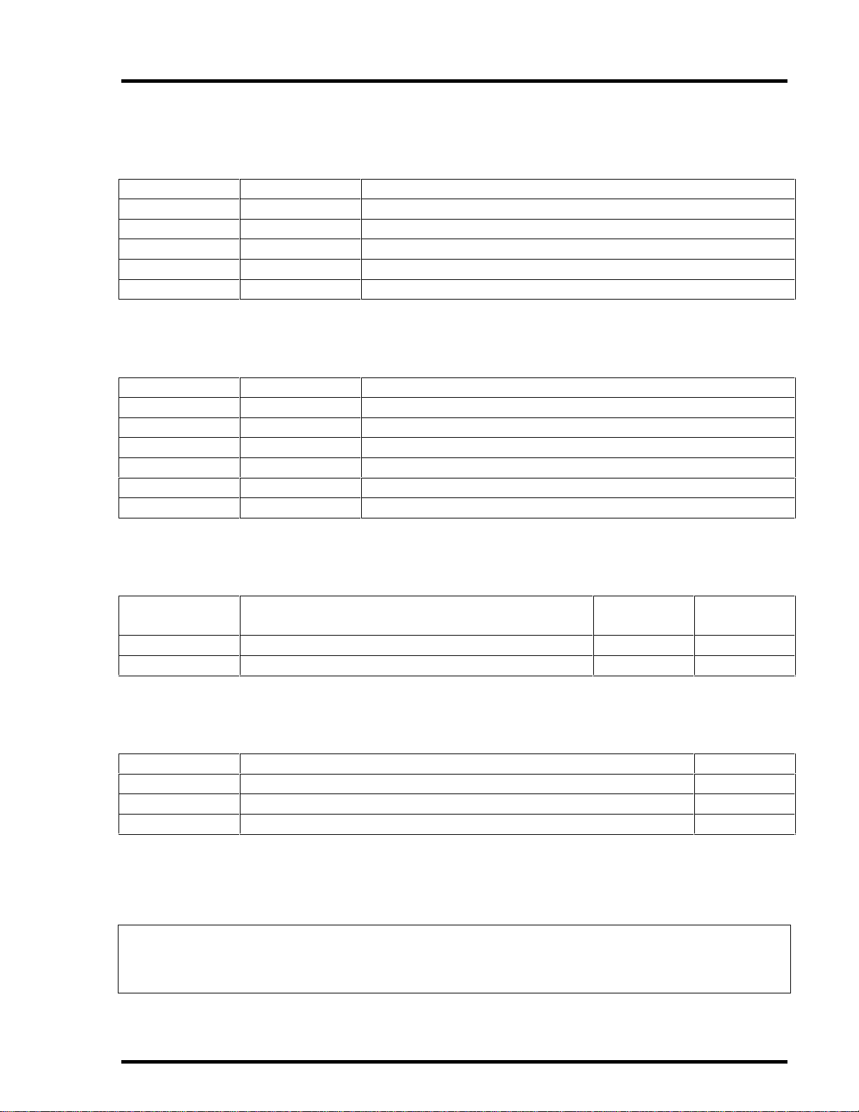
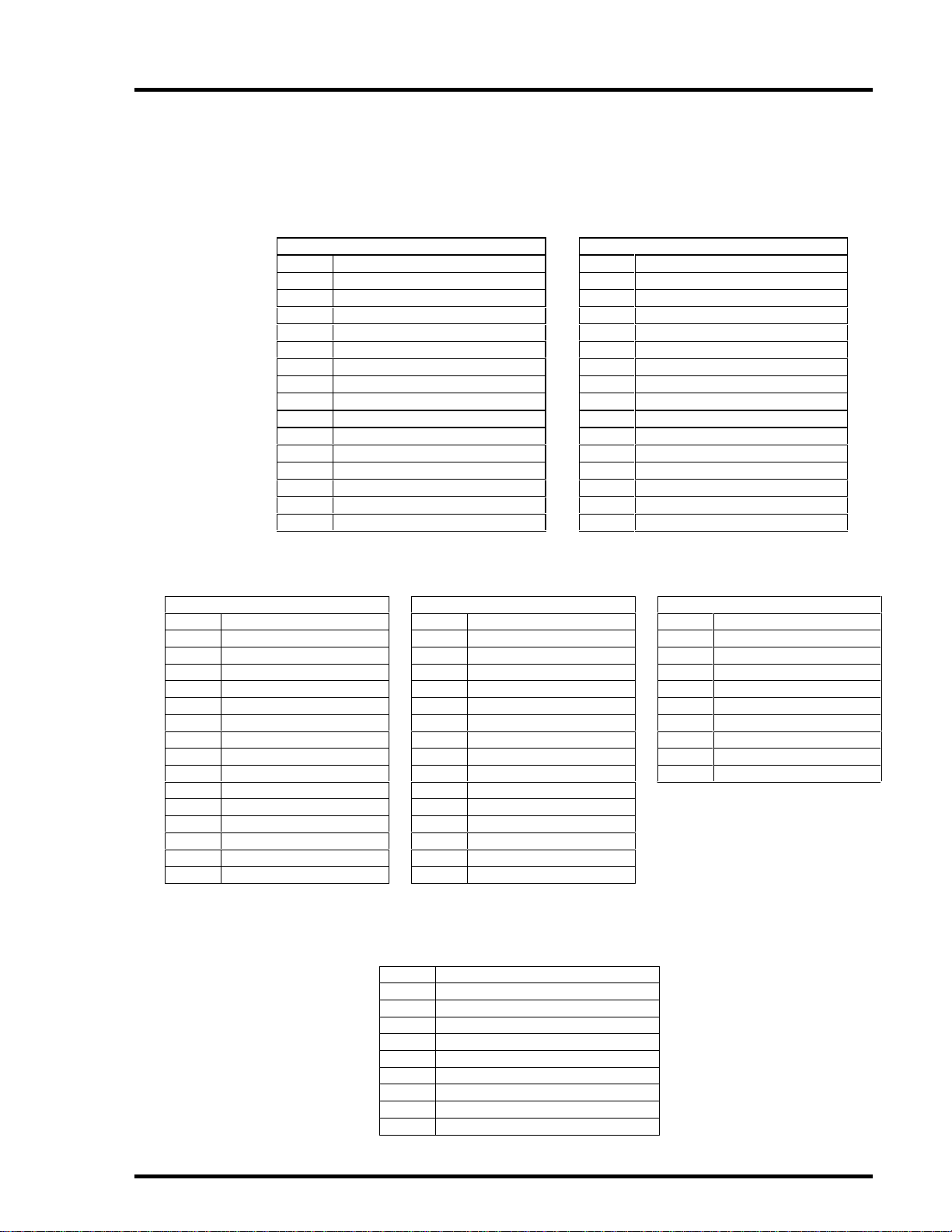
3.7 Mating Connector Information
All wiring harnesses to the unit are supplied and fabricated by the
installing agency.
Model # Pin # Connector Mating Connector
MCD-102-CH-1 P1 RD15M10JV30 RD15F10JVL0
P2 RD15F10JVL0 RD15M10JV30
MCD-102-CH-2 P1 DAMA-15P
D20418-2 Female Screwlock DAMA-15S
P2 DAMA-15S
D20419-18 Male Screwlock DAMA-15P
MCD-102-RU-1 (-3) RD15M10JV30 RD15F10JVL0
MCD-102-RU-2 (-4) DAMA-15P
D20418-2 Female Screwlock DAMA-15S
MCD-102-CP-1 RD9M10JVL0 RD9F10JVL30
MCD-102-CP-2 DEMA-9P
D20418-2 Female Screwlock DEMA-9S
MCD-103-CH-1 P1 RD15M10JV30 RD15F10JVL0
P2 RD15F10JVL0 RD15M10JV30
P3 RD9F10JV30 RD9M10JVL0
MCD-103-CH-2 P1 DAMA-15P
D20418-2 Female Screwlock DAMA15S
P2 DAMA-15S
D20419-18 Male Screwlock DAMA-15P
P3 DEMA-9S
D20419-21 Male Screwlock DEMA-9P
MCD-104-01-1 P1 RD15M10JV30 RD15F10JVL0
MCD-104-01-2 P1 DAMA-15P
D20418-2 Female Screwlock DAMA-15S