Audioaccess MA-362 Service User manual

MA-362
Twelve Channel
Amplifier
502-00085-00
Quick Start Guide
®

1
MA-362
Twelve Channel Amplifier
Quick Start Guide
Important Notes ☞Make sure you give the IMPORTANT SAFETY PRECAUTIONS sheet to
your customer.
☞Like any other high-powered amplifier, the MA-362 will generate heat
during normal operation. In order to provide sufficient air flow around
the MA-362 when installed on the shelf, make sure there is at least
three inches of clearance above the amplifier and at least two inches of
clearance on each side. When installed in a rack, make sure there is at
least three inches of clearance to the components both above and below
the MA-362.
Overview The MA-362 is a twelve-channel amplifier organized as six two-channel
pairs (zones). Each of these pairs can be operated in one of four ways:
• as a stereo pair
• left and right inputs summed to mono and routed to each channel
of the pair
• bridged with the left input supplying the input signal
• bridged with the right input supplying the input signal
Each pair can be triggered or turned on either by sensing the presence of an
input signal or with an applied trigger voltage. Zone 1 can also be selected for
“Always On” operation. The MA-362 features a powerful bussing architecture
that allows one input pair to supply multiple amplifier zones.
Controls
Input Link Switch Selects local RCA jacks (LOCAL) or RCA jacks on Zone to the immediate
left (LINK) as input source.
Mode Switch Selects Stereo (STEREO), Summed to Mono (MONO), Bridged using left
input (BRIDGE/L), or Bridged using right input (BRIDGE/R) operation mode.
Trigger Switch Selects trigger source for zone: signal sensing (SIGNAL), voltage trigger
(12V), or trigger signal of the Zone to immediate left (LINK).
Input Level Independently adjusts the left and right amplifier input level from 0dB (full
CW) to –20dB (full CCW). In Mono Mode, Input level controls adjust the
level of each channel and do not effect the L/R mix.

2
Stereo Operation ❑Connect the left and right input signals to the left and right RCA jacks
of a MA-362 Zone.
❑Set Input Link to “LOCAL” (note: Zone 1 always uses the local input).
❑Set Mode to “STEREO”.
❑Set Trigger to “SIGNAL” for signal sensing and “12V” for voltage trigger.
If applicable, connect trigger control signal to the +12V Trigger Input.
❑Connect speaker leads to the Zone’s LEFT and RIGHT SPEAKER OUTPUTS.
❑Starting with the controls at maximum (full clockwise rotation), adjust
left or right Input Level controls as needed to balance the sound output
from each speaker.
Summed to Mono
Operation
Configure as for Stereo Operation except set Mode to “MONO”
Stereo
Mono
Bridge/R
Bridge/L
Link
Signal
12V
Link
Local
Input
Link Mode
Input +12V Trigger
Input
Input Level Zone
3
Trigger
LR
+
–
LR
SUMMED TO MONO OPERATION
Signal Sensing 12 Volt Trigger
L & R Audio IN
Stereo
Mono
Bridge/R
Bridge/L
Link
Signal
12V
Link
Local
Input
Link Mode
Input +12V Trigger
Input
Input Level Zone
4
Trigger
LR
+
–
LR
L & R Audio IN 12V Trigger
Stereo
Mono
Bridge/R
Bridge/L
Link
Signal
12V
Link
Local
Input
Link Mode
Input +12V Trigger
Input
Input Level Zone
3
Trigger
LR
+
–
LR
STEREO OPERATION
Signal Sensing 12 Volt Trigger
L & R Audio IN
Stereo
Mono
Bridge/R
Bridge/L
Link
Signal
12V
Link
Local
Input
Link Mode
Input +12V Trigger
Input
Input Level Zone
4
Trigger
LR
+
–
LR
L & R Audio IN 12V Trigger

3
Bridged Operation Method One
☞You must use Method One if you are bussing zones.
❑Connect the left and right input signals to the Left and Right RCA jacks
of a MA-362 Zone.
❑Set Input Link to “LOCAL”.
❑Set Mode to “BRIDGE/L”.
❑Set Trigger to “SIGNAL” for signal sensing and “12V” for voltage trigger.
If applicable, connect trigger control signal to the +12V Trigger Input.
❑Connect left speaker leads to the Zones RIGHT + (+ speaker lead) and
LEFT + (– speaker lead) SPEAKER OUTPUTS.
❑On the zone to the immediate right, set Input Link to “LINK”.
❑Set Mode to “BRIDGE/R”.
❑Set Trigger to “LINK”.
❑Connect right speaker leads to the Zone’s RIGHT + (+ speaker lead) and
LEFT + (– speaker lead) SPEAKER OUTPUTS.
❑Starting with the controls at maximum (full clockwise rotation), adjust
left Input Level control on the first zone and right Input Level control on
the second zone as needed to balance the sound output from each speaker.
Method Two
❑Connect the left input signal to the Left RCA jack of a MA-362 Zone.
❑Set Input Link to “LOCAL”.
❑Set Mode to “BRIDGE/L”.
❑Set Trigger to “SIGNAL” for signal sensing and “12V” for voltage trigger.
If applicable, connect trigger control signal to the +12V Trigger Input.
❑Connect left speaker leads to the Zones RIGHT + (+ speaker lead) and
LEFT + (– speaker lead) SPEAKER OUTPUTS.
Stereo
Mono
Bridge/R
Bridge/L
Link
Signal
12V
Link
Local
Input
Link Mode
Input +12V Trigger
Input
Input Level Zone
3
Trigger
LR
+
–
LR
BRIDGED OPERATION (Method One)
L & R Audio IN
To
LEFT
Speaker
Stereo
Mono
Bridge/R
Bridge/L
Link
Signal
12V
Link
Local
Input
Link Mode
Input +12V Trigger
Input
Input Level Zone
4
Trigger
LR
+
–
LR
L & R Audio IN 12V Trigger
To
RIGHT
Speaker
L
Use Level
Stereo
Mono
Bridge/R
Bridge/L
Link
Signal
12V
Link
Local
Input
Link Mode
Input +12V Trigger
Input
Input Level Zone
5
Trigger
LR
+
–
LR
To
LEFT
Speaker
Stereo
Mono
Bridge/R
Bridge/L
Link
Signal
12V
Link
Local
Input
Link Mode
Input +12V Trigger
Input
Input Level Zone
6
Trigger
LR
+
–
LR
To
RIGHT
Speaker
Bridged Signal Sensing Bridged 12 Volt Trigger
R
Use Level L
Use Level R
Use Level

4
❑On the zone to the immediate right, connect the right input signal to the
Right RCA jack.
❑Set Input Link to “LOCAL”.
❑Set Mode to “BRIDGE/R”.
❑If the trigger in the first zone is set to signal sensing, set Trigger to
“SIGNAL”. Otherwise, set Trigger to “Link”.
❑Connect right speaker leads to the Zones RIGHT + (+ speaker lead) and
LEFT + (– speaker lead) SPEAKER OUTPUTS.
❑Starting with the controls at maximum (full clockwise rotation), adjust
left Input Level control on the first zone and right Input Level control on
the second zone as needed to balance the sound output from each speaker.
Bussed Operation Multiple zones can be bussed together. The RCA jacks on one Zone are used
to supply signal to the zone(s) to its immediate right. The unused RCA jacks
on any linked zone may be used as a buss output to connect to another
MA-362 or other amplifier.
❑Connect the left and right input signals to the Left and Right RCA jacks
of a MA-362 Zone.
❑Set Input Link switch to “LOCAL”.
❑Set Mode to “STEREO”.
❑Set Trigger to “SIGNAL” for signal sensing and “12V” for voltage trigger.
If applicable, connect trigger control signal to the +12V Trigger Input.
❑On the zone to the immediate right, set Input Link to “LINK”.
❑Set Mode to “STEREO”.
❑Set Trigger to “LINK”.
❑For each additional zone in the same buss group, set Input Link to
“LINK”, Mode to “STEREO” and Trigger to “LINK”.
Stereo
Mono
Bridge/R
Bridge/L
Link
Signal
12V
Link
Local
Input
Link Mode
Input +12V Trigger
Input
Input Level Zone
3
Trigger
LR
+
–
LR
BRIDGED OPERATION (Method Two)
Left Audio IN Right Audio IN
To
LEFT
Speaker
Stereo
Mono
Bridge/R
Bridge/L
Link
Signal
12V
Link
Local
Input
Link Mode
Input +12V Trigger
Input
Input Level Zone
4
Trigger
LR
+
–
LR
Left Audio IN Right Audio IN
12V Trigger
To
RIGHT
Speaker
L
Use Level
Stereo
Mono
Bridge/R
Bridge/L
Link
Signal
12V
Link
Local
Input
Link Mode
Input +12V Trigger
Input
Input Level Zone
5
Trigger
LR
+
–
LR
To
LEFT
Speaker
Stereo
Mono
Bridge/R
Bridge/L
Link
Signal
12V
Link
Local
Input
Link Mode
Input +12V Trigger
Input
Input Level Zone
6
Trigger
LR
+
–
LR
To
RIGHT
Speaker
Bridged Signal Sensing Bridged 12 Volt Trigger
R
Use Level L
Use Level R
Use Level

5
Multiple Busses Multiple busses (groups of linked zones) can be created. Follow the steps
described for Bussed Operation and simply make sure the Input Link
switch of the first zone of each buss group is set to “LOCAL”. Connect the
audio signals for the bussed group to the Left and Right RCA jacks of this
first zone.
Stereo
Mono
Bridge/R
Bridge/L
Link
Signal
12V
Link
Local
Input
Link Mode
Input +12V Trigger
Input
Input Level Zone
2
Trigger
LR
+
–
LR
MULTIPLE BUSS OPERATION (Stereo Mode)
L & R Audio IN
Stereo
Mono
Bridge/R
Bridge/L
Link
Signal
12V
Link
Local
Input
Link Mode
Input +12V Trigger
Input
Input Level Zone
3
Trigger
LR
+
–
LR
12V Trigger
Stereo
Mono
Bridge/R
Bridge/L
Link
Signal
12V
Link
Local
Input
Link Mode
Input +12V Trigger
Input
Input Level Zone
4
Trigger
LR
+
–
LR
L & R Audio IN
Stereo
Mono
Bridge/R
Bridge/L
Link
Signal
12V
Link
Local
Input
Link Mode
Input +12V Trigger
Input
Input Level Zone
6
Trigger
LR
+
–
LR
L & R Audio OUT
(to another amplifier)
12V Trigger
Stereo
Mono
Bridge/R
Bridge/L
Link
Signal
12V
Link
Local
Input
Link Mode
Input +12V Trigger
Input
Input Level Zone
2
Trigger
LR
+
–
LR
BUSS OPERATION (Stereo Mode)
L & R Audio IN
Stereo
Mono
Bridge/R
Bridge/L
Link
Signal
12V
Link
Local
Input
Link Mode
Input +12V Trigger
Input
Input Level Zone
3
Trigger
LR
+
–
LR
12V Trigger
Stereo
Mono
Bridge/R
Bridge/L
Link
Signal
12V
Link
Local
Input
Link Mode
Input +12V Trigger
Input
Input Level Zone
6
Trigger
LR
+
–
LR
L & R Audio OUT
(to another amplifier)

http://www.audioaccess.com
is a registered trademark of Harman International
a Harman International company
502-00085-00 ©11/2001 Audioaccess. All rights reserved.
Other manuals for MA-362 Service
2
Table of contents
Other Audioaccess Amplifier manuals
Audioaccess
Audioaccess PX-612 User manual
Audioaccess
Audioaccess PX-600 User manual
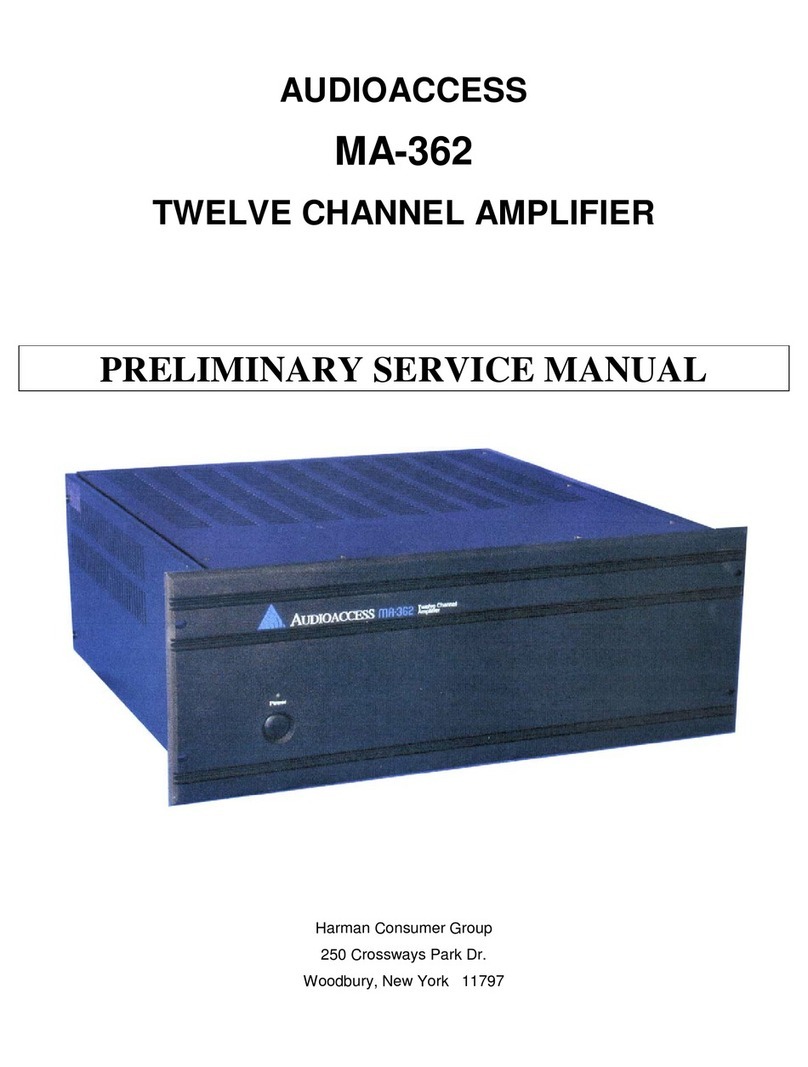
Audioaccess
Audioaccess MA-362 Service User manual
Audioaccess
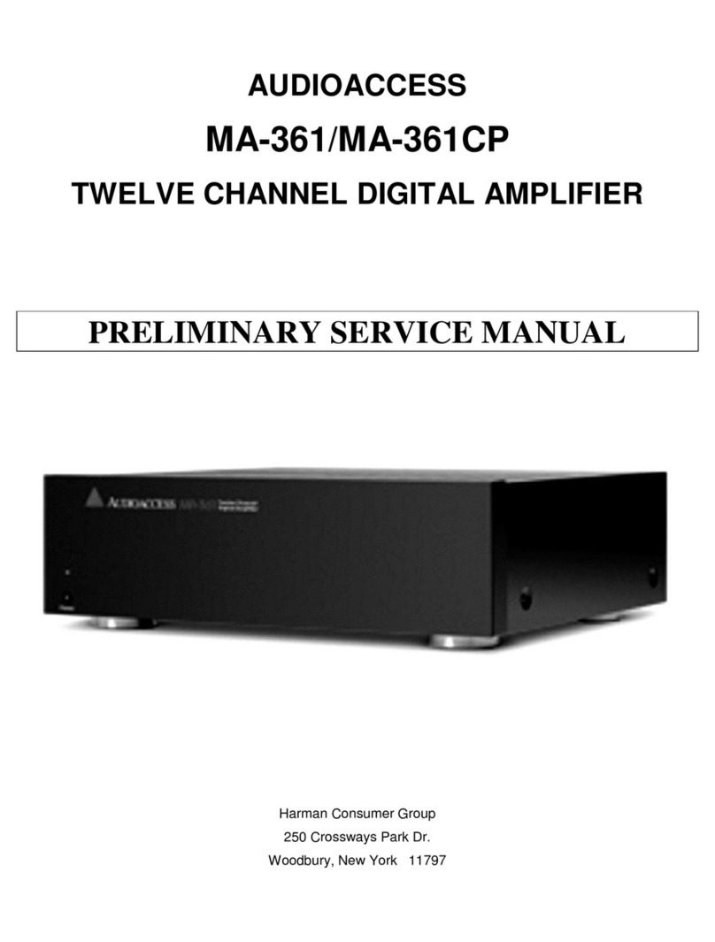
Audioaccess MA-361 Service User manual
Audioaccess
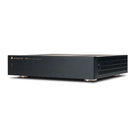
Audioaccess PX-612 User manual
Audioaccess
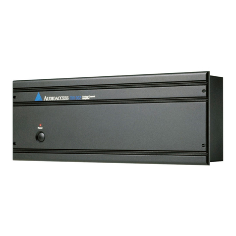
Audioaccess MA-362 Service Manual
Audioaccess
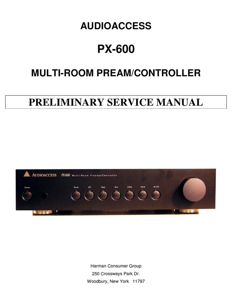
Audioaccess PX-600 Installation and operating instructions
Audioaccess
Audioaccess PX-600 User manual
