AudioArts Engineering W-12 User manual

TECHNICAL MANUAL
September 2007
W - 12
DIGITAL RADIO CONSOLE

R-16 / Dec 1997
W-12 Digital Radio Console Technical Manual - 1st EditionW-12 Digital Radio Console Technical Manual - 1st Edition
W-12 Digital Radio Console Technical Manual - 1st EditionW-12 Digital Radio Console Technical Manual - 1st Edition
W-12 Digital Radio Console Technical Manual - 1st Edition
©2007 Audioarts®Engineering*
AUDIOARTS ENGINEERING
600 Industrial Drive
New Bern, North Carolina 28562
252-638-7000
*a division of Wheatstone Corporation
W-12/ September 2007

AA
AA
ATTENTIONTTENTION
TTENTIONTTENTION
TTENTION
RR
RR
READEAD
EADEAD
EAD MM
MM
M
EE
EE
E!!
!!
!
W-12 / November 2007
Attention!
FF
FF
Federal Communications Commission (FCC) Complianceederal Communications Commission (FCC) Compliance
ederal Communications Commission (FCC) Complianceederal Communications Commission (FCC) Compliance
ederal Communications Commission (FCC) Compliance
Notice:Notice:
Notice:Notice:
Notice:
Radio FRadio F
Radio FRadio F
Radio Frequency Noticerequency Notice
requency Noticerequency Notice
requency Notice
NOTE:NOTE:
NOTE:NOTE:
NOTE: This equipment has been tested and found to comply with the
limits for a Class A digital device, pursuant to Part 15 of the FCC rules. These
limits are designed to provide reasonable protection against harmful
interference when the equipment is operated in a commercial environment.
This equipment generates, uses, and can radiate radio frequency energy
and, if not installed and used in accordance with the instruction manual,
may cause harmful interference to radio communications. Operation of this
equipment in a residential area is likely to cause harmful interference in
which case the user will be required to correct the interference at his own
expense.
This is a Class A product. In a domestic environment, thisThis is a Class A product. In a domestic environment, this
This is a Class A product. In a domestic environment, thisThis is a Class A product. In a domestic environment, this
This is a Class A product. In a domestic environment, this
product may cause radio interference, in which case, theproduct may cause radio interference, in which case, the
product may cause radio interference, in which case, theproduct may cause radio interference, in which case, the
product may cause radio interference, in which case, the
user may be required to take appropriate measures.user may be required to take appropriate measures.
user may be required to take appropriate measures.user may be required to take appropriate measures.
user may be required to take appropriate measures.
This equipment must be installed and wired properly in order to assure
compliance with FCC regulations.
Caution!Caution!
Caution!Caution!
Caution!
Any modifications not expressly approved in writing byAny modifications not expressly approved in writing by
Any modifications not expressly approved in writing byAny modifications not expressly approved in writing by
Any modifications not expressly approved in writing by
Wheatstone could void the user's authority to operate this equipment.Wheatstone could void the user's authority to operate this equipment.
Wheatstone could void the user's authority to operate this equipment.Wheatstone could void the user's authority to operate this equipment.
Wheatstone could void the user's authority to operate this equipment.

AA
AA
ATTENTIONTTENTION
TTENTIONTTENTION
TTENTION
RR
RR
READEAD
EADEAD
EAD MM
MM
MEE
EE
E!!
!!
!
W-12 / November 2007
Installing the Clamp-Installing the Clamp-
Installing the Clamp-Installing the Clamp-
Installing the Clamp-on Fon F
on Fon F
on Ferriteerrite
erriteerrite
errite
One ferrite has been included with your W-12 installation kit to help suppress
undesired electromagnetic interference. Rather than install it at the factory,
this ferrite has been packaged separately so that you can attach it after the
cable has been run, thus easing installation.
Place the ferrite on the console end of the cable that connects the W-12 console
to the power supply.
To attach the ferrite:
1. Place the ferrite on the cable so that the ferrite's curved inner edge rests
firmly on the cable, close to the connector that plugs to the console power
connector.
2. Press the two halves of the ferrite closed until they snap together.
3. Place the split washers (2) on the cable on the each side of the ferrite.
4. Attach the cable ties (2) just below the washers so that the ferrite cannot slide
down the cable.
Refer to the following figure.
W-12 / March 2008
Attach cable ties hereAttach cable ties here
Attach cable ties hereAttach cable ties here
Attach cable ties here
FerriteFerrite
FerriteFerrite
Ferrite
Console endConsole end
Console endConsole end
Console end
power connectorpower connector
power connectorpower connector
power connector
WasherWasher
WasherWasher
Washer
WasherWasher
WasherWasher
Washer

RR
RR
READEAD
EADEAD
EAD MM
MM
M
EE
EE
E!!
!!
!
W-12 / Sep 2007
IMPORTANT!
WW
WW
W-12 A-12 A
-12 A-12 A
-12 Audio Levelsudio Levels
udio Levelsudio Levels
udio Levels
GeneralGeneral
GeneralGeneral
General
All professional digital audio broadcast consoles manufactured by Audioarts
are hybrid in nature. That is, they allow the user to connect both analog and
digital domain sources and provide both analog and digital outputs. While this
approach allows for greater flexibility when interconnecting source and
destination equipment, the user must be aware of what levels to expect when
applying, say, a digital input and measuring at an analog output.
Gain StructurGain Structur
Gain StructurGain Structur
Gain Structuree
ee
e
Broadcast consoles by design have various electronic stages at which the
signal level may be amplified or attenuated. The primary stages are the A-D
converter input, channel fader, DSP mixing, and the bus output D-A converters.
The sum of these gain stages is commonly referred to as the console’s “gain
structure.” Wheatstone consoles are factory calibrated for 0dB or “unity gain”
when the input channel fader is set to nominal (-12dB).
The following is a stage by stage breakdown of the W-12 console’s gain stages:
Analog Input (A-D Converter)Analog Input (A-D Converter)
Analog Input (A-D Converter)Analog Input (A-D Converter)
Analog Input (A-D Converter)
• TheADCinputcircuitcardsaredesignedsothata+4dBuinputsignalwillyield
a -20dBFS digital output with the channel fader at nominal.
• An input gain adjust switch setting can be changed to increase the gain by 8dB
to allow for interfacing unbalanced equipment.
•Miclevelpreampshavetrimpotsformatchingvariousmicrophonesourcelevels
to the console’s normal +4dBu analog operating level.
DSP GainDSP Gain
DSP GainDSP Gain
DSP Gain
•Setinfirmwareforunitygain(-20dBFSinputyieldsa-20dBFSoutputwhenthe
input channel fader is set to nominal), digital attenuation may be applied on a
channel by channel basis via a dipswitch setting.
Analog Bus Output Gain (D-A Converter)Analog Bus Output Gain (D-A Converter)
Analog Bus Output Gain (D-A Converter)Analog Bus Output Gain (D-A Converter)
Analog Bus Output Gain (D-A Converter)
• The analog output DAC circuits are designed so that a -20dBFS digital input
signal will yield a +4dBu analog output with the channel fader at nominal.

RR
RR
READEAD
EADEAD
EAD MM
MM
M
EE
EE
E!!
!!
!
W-12 / Sep 2007
AA
AA
Audio Referudio Refer
udio Referudio Refer
udio Reference Levelsence Levels
ence Levelsence Levels
ence Levels
All consoles are fully factory calibrated and will comply with the following
reference level:
-20dBFS digital = +4dBu analog = 0VU Note: 0dBu = .775v rms
+4dBu = 1.23v rms
These settings will provide a headroom of 20dB over the nominal input signal of
+4dBu analog, or -20dBFS digital.
Note that due to the lack of level standards in the digital domain, headroom
available for digital sources will be entirely dependant on the source. In fact, CD's
are frequently made with less than 1dB of digital headroom, and any boosting of
digital CD levels in the console by moving the fader up above the nominal can
result in overload distortion for that channel. For this reason, a dipswitch allows
for digital attenuation on a fader by fader basis; digital sources can be conveniently
attenuated this way to guard against digital overload caused by not enough
headroom on the digital source. Since the W-12 console meters are true digital
reading meters, they will always show the console's digital levels, and whether
there are any "overs" in the signal. By pressing a channel's "CUE" button, the
switched meters will show the digital level of that channel's source. By using the
program and watching these meters, the amount of attenuation can be adjusted
to meet your headroom requirements.
TT
TT
Typical Input Levelsypical Input Levels
ypical Input Levelsypical Input Levels
ypical Input Levels
Mic Inputs Nominal = -50dBm, 150ohm Maximum = -26dBm
Analog Inputs Nominal = +4dBu Maximum = +24dBu
Digital Inputs Nominal = -20dBFS Maximum = 0dBFS
II
II
IMPORTANTMPORTANT
MPORTANTMPORTANT
MPORTANT

page Contents – 1
W-12 / Sep 2007
CONTENTS
W-12 Technical Manual
Table of Contents
Chapter 1 – Installation and Power
Unpacking and Installing the Console ........................................1-2
System Ground .............................................................................1-3
Further Grounding Details ................................................................................... 1-4
Power Supply ................................................................................1-5
Energizing ............................................................................................................ 1-6
Audio and Control Wiring.............................................................1-6
Digital Audio Connections ................................................................................... 1-6
Unbalanced Connections (analog audio) ............................................................ 1-7
W-12 Console Rear Drawing ........................................................1-8
Hook-Ups .......................................................................................1-9
Audio Connections.................................................................................................... 1-9
MPW-12 Mic Preamp Connections ..................................................................... 1-9
ADC -W12 Analog Input Connections—DB-25 .................................................. 1-10
SRC -W12 Digital Input Connections—DB-25 ................................................... 1-10
Monitor Output Connection—DB-25................................................................... 1-10
Program Analog Output & Caller Connections—DB-25..................................... 1-11
Program Digital Output & External Input Connections—DB-25......................... 1-12
Logic Connections ................................................................................................... 1-12
Logic Port Connections—DB-25 ........................................................................ 1-12
Tally—3-pin Plug Terminal ................................................................................. 1-13
Logic Port Mapping............................................................................................. 1-13
Remote ON, OFF, and Cough............................................................................ 1-13
External START & STOP ................................................................................... 1-13
Ready.................................................................................................................. 1-13
Talkback to Control Room .................................................................................. 1-14
On Tally .............................................................................................................. 1-14
Tally B ................................................................................................................. 1-15
Mic Preamp Connection Pinouts ............................................... 1-16
Analog Input Connection Pinouts ............................................. 1-17
Digital Input Connection Pinouts .............................................. 1-18
Monitor Connection Pinouts ...................................................... 1-19
PGM Analog Output & Caller Connection Pinouts .................. 1-20
PGM Digital Output & External Input Connection Pinouts...... 1-21
Logic Connection Pinouts.......................................................... 1-22
Input Daughter Card Installation ............................................... 1-23
Hand Crimp Tool Wiring Instructions ....................................... 1-25
Pin Extractor Instructions .......................................................... 1-26

page Contents – 2
W-12 / Sep 2007
CONTENTS
Chapter 2 - Console Features
Overview ..................................................................................... 2-2
W-12 Console Layout Drawing ................................................. 2-3
Mic Preamp ................................................................................. 2-4
Line Level Inputs........................................................................ 2-4
Outputs ....................................................................................... 2-5
Mute and Tally ............................................................................ 2-5
Console Programming Options ................................................ 2-6
FADER 1 - 12 Dipswitches ..................................................................................... 2-6
Attenuation......................................................................................................... 2-6
PGM 3 Bus Pre-Fader ....................................................................................... 2-6
CR Mute............................................................................................................. 2-6
Logic Assign ...................................................................................................... 2-7
A Note On Logic Port Assignments................................................................... 2-7
CALLER Dipswitch ................................................................................................. 2-7
Cue Dropout ...................................................................................................... 2-7
Cue Pre/Post ..................................................................................................... 2-7
CR Mutes ........................................................................................................... 2-7
Logic Assign ...................................................................................................... 2-8
Gain Trimpot ...................................................................................................... 2-8
MONITOR 1 Dipswitch ........................................................................................... 2-8
Split Cue, Control Room.................................................................................... 2-8
Cue Interrupt...................................................................................................... 2-8
Cue Mute ........................................................................................................... 2-8
Phantom Power ................................................................................................. 2-8
EFS - European Fader Start.............................................................................. 2-9
MONITOR 2 Dipswitch ........................................................................................... 2-9
Split Cue, Headphone ....................................................................................... 2-9
Talkback to Studio ............................................................................................. 2-9
Console Sample Rate........................................................................................... 2-10
Chapter 3 - Controls and Functions
Input Panel (IP-W12) .................................................................. 3-2
Source Select .................................................................................................... 3-3
Program Assign ................................................................................................. 3-3
Cue Button......................................................................................................... 3-3
Fader.................................................................................................................. 3-3
ON/OFF Switches.............................................................................................. 3-3
Master Panel (MST-W12) ........................................................... 3-4
Caller Input ............................................................................................................. 3-5
Program Assign ................................................................................................. 3-5
Com Button ........................................................................................................ 3-5
Fader.................................................................................................................. 3-5
ON/OFF Switch.................................................................................................. 3-5
Caller Set-Ups ................................................................................................... 3-6
Monitor Section....................................................................................................... 3-7
Control Room Program Select .......................................................................... 3-8
Control Room EXT Switch................................................................................. 3-8
Control Room Level Control .............................................................................. 3-8
Cue Level Control .............................................................................................. 3-8
W-12 / Apr 2008

page Contents – 3
W-12 / Sep 2007
CONTENTS
Headphone Level Control.................................................................................. 3-9
Studio EXT Switch ............................................................................................. 3-9
Studio Level Control .......................................................................................... 3-9
TB Button ........................................................................................................... 3-9
TB Level Control ................................................................................................ 3-9
Meters (VU-W12).................................................................................................. 3-10
VU Meter Pairs ................................................................................................ 3-10
Meters Select Buttons ..................................................................................... 3-10
Chapter 4 - Schematic and Load Sheet Drawings
W-12 Flow Diagrams
Inputs, Caller Feed, and Channel Logic................................................................. 4-2
Monitors .................................................................................................................. 4-3
Master Outputs ....................................................................................................... 4-4
INS-6 Input Panel Switch Board
Schematic ............................................................................................................... 4-5
Load Sheet.............................................................................................................. 4-7
MNS-12 Master Panel Switch Board
Schematic ............................................................................................................... 4-8
Load Sheet.............................................................................................................. 4-9
MNW-12 Monitor Board
Schematic ............................................................................................................. 4-10
Load Sheet............................................................................................................ 4-13
MPW-12 Mic Preamps
Schematic ............................................................................................................. 4-14
Load Sheet............................................................................................................ 4-15
ADCW-12 2 A/B Analog Inputs
Schematic ............................................................................................................. 4-16
Load Sheet............................................................................................................ 4-18
SRCW-12 2 A/B Digital Inputs
Schematic ............................................................................................................. 4-19
Load Sheet............................................................................................................ 4-20
MBW-12 Mother Board
Schematic ............................................................................................................. 4-21
Load Sheet............................................................................................................ 4-26
ONS-6 On/Off Switch Card
Schematic ............................................................................................................. 4-27
Load Sheet............................................................................................................ 4-28
PHONS-12 Phone On/Off Switch Card
Schematic ............................................................................................................. 4-29
Load Sheet............................................................................................................ 4-30
SPS-100 Power Supply
Schematic ............................................................................................................. 4-31
Load Sheet............................................................................................................ 4-32
Appendix 1
Replacement Parts List .............................................................A-2

INSTALLATION and POWER
page 1 – 1
W-12 / Sep 2007
Installation and Power
Chapter Contents
Unpacking and Installing the Console ........................................1-2
System Ground .............................................................................1-3
Further Grounding Details .................................................................................... 1-4
Power Supply ................................................................................1-5
Energizing............................................................................................................. 1-6
Audio and Control Wiring.............................................................1-6
Digital Audio Connections .................................................................................... 1-6
Unbalanced Connections (analog audio) ............................................................. 1-7
W-12 Console Rear Drawing ........................................................1-8
Hook-Ups .......................................................................................1-9
Audio Connections................................................................................................ 1-9
MPW-12 Mic Preamp Connections ................................................................. 1-9
ADC -W12 Analog Input Connections—DB-25.............................................. 1-10
SRC -W12 Digital Input Connections—DB-25 ............................................... 1-10
Monitor Output Connection—DB-25............................................................... 1-10
Program Analog Output & Caller Connections—DB-25................................. 1-11
Program Digital Output & External Input Connections—DB-25..................... 1-12
Logic Connections ............................................................................................... 1-12
Logic Port Connections—DB-25 .................................................................... 1-12
Tally—3-pin Plug Terminal ............................................................................. 1-13
Logic Port Mapping......................................................................................... 1-13
Remote ON, OFF, and Cough........................................................................ 1-13
External START & STOP ............................................................................... 1-13
Ready ............................................................................................................. 1-13
Talkback to Control Room .............................................................................. 1-14
On Tally .......................................................................................................... 1-14
Tally B............................................................................................................. 1-15
Mic Preamp Connection Pinouts ................................................1-16
Analog Input Connection Pinouts ..............................................1-17
Digital Input Connection Pinouts ...............................................1-18
Monitor Connection Pinouts .......................................................1-19
PGM Analog Output & Caller Connection Pinouts ...................1-20
PGM Digital Output & External Input Connection Pinouts.......1-21
Logic Connection Pinouts...........................................................1-22
Input Daughter Card Installation ................................................1-23
Hand Crimp Tool Wiring Instructions ........................................1-25
Pin Extractor Instructions ...........................................................1-26
INSTALLATION and POWER
page 1 – 2
W-12 / Sep 2007
Installation and Power
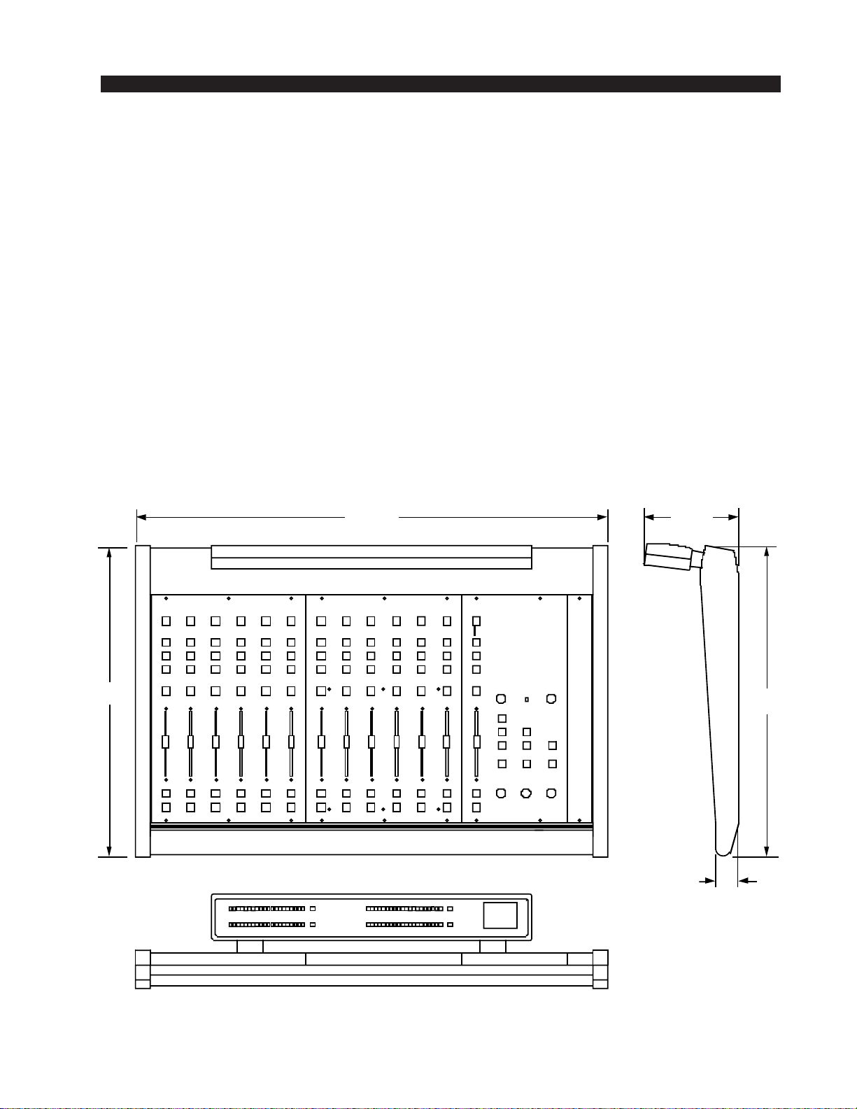
Unpacking and Installing the Console
The W-12 console, with its power supply, connecting cable, and
technical manual, is shipped in one packing box. The console can be
unpackedbyonepersonbygraspingtheconsoleatbothsides,andlifting
itupwardoutofthebox.Removepackingmaterialsandstoretheminthe
box for future use. Carefully place the console on your countertop (the
W-12 audio console is designed for countertop placement). Avoid prox-
imity to any electromagnetic fields, such as large power transformers,
motors, and fluorescent lighting fixtures.
NOTE: This console
contains static-sensi-
tive devices. Normal
precautions against
staticdischargeshould
be observed.
20.500
6.250
1.500
31.125
20.500

INSTALLATION and POWER
page 1 – 3
W-12 / Sep 2007
CONSOLE
2-TRACK
MULTI-TRACK
AC BREAKER
BOX
DEVICE 1
DEVICE 2
DEVICE N
CONSOLE POWER SUPPLY
CONTROL ROOM POWER AMP
STUDIO POWER AMP
OTHER
POWER COMPANY
EARTH GROUND
HEAVY
(#4 or #6)
COPPER
WIRE
HIGH POWER
EQUIPMENT RACK
COPPER ROD
SOIL
3-wire ground or separate wire run from chassis
EFFECTS RACK
MIC PANEL
GND
TYPICAL SYSTEM
GROUNDING SCHEME
etc.
3–5 ft.
Tie the console ground lug
terminal strip to the system
earthground. Tieeverypiece
of equipment in the entire
audio system to the console
ground lug terminal strip.
System Ground
The first step is to ground the console.
Note that as supplied from the factory, console rackmount power
supply common, audio ground, and the W-12 mainframe are connected
togetherattheconsole,butareNOTconnectedtoelectricalgroundandthe
chassis of the power supply. Safety requirements dictate that a positive
connectionfromtheconsolemainframetoelectricalgroundbemadeinthe
completedinstallation.Usethegroundinglugontherearofthemainframe
to establish your system ground. The grounding lug may be found at the
rear of the console, on the rear frame panel, to the left if you are looking
at the rear of the console.
The system ground serves two important purposes:
(1) It provides a zero signal reference point for the entire audio system;
(2) It assures safety from electrical shock.
There exist two terms that one encounters in a discussion of ground:
(A)EARTHGROUND,whichisusuallyaheavycopperroddrivenintothesoil
adjacent to the building (around 6 feet down) or a connection to the copper water
pipes leading into the building. Either is acceptable (unless, of course, the water
pipe is made of plastic).

INSTALLATION and POWER
page 1 – 4
W-12 / Sep 2007
(B) THE POWER COMPANY EARTH CONDUCTOR that enters the build-
ing at the power line breaker box; this conductor should be (and is often by code)
tiedto theabove-mentioned earth groundat onepoint. This pointis theSYSTEM
EARTH GROUND.
TIE THE CONSOLE GROUND LUG TO THE SYSTEM EARTH
GROUND. TIE EVERY PIECE OF EQUIPMENT IN THE ENTIRE
AUDIO SYSTEM TO THE CONSOLE GROUND LUG. If the system
earthground point is inaccessible, tie the consoleground lugto thepower
company earth conductor at the main breaker box (see drawing "Typical
Grounding Scheme" on previous page).
Each piece of equipment should be connected by its own ground wire
(usually the round third pin on the AC cord). This means that every AC
outlet must have a separate conductor run to the console ground lug; the
outletscannotbedaisy-chainedasisnormallyencounteredincommercial
and residential AC systems. Any equipment not supplied with 3-wire AC
cables must have individual ground wires (16 gauge or larger) connected
to their chassis grounds and then run to the console ground lug terminal
strip.
Further Grounding Details
Check all equipment to be absolutely certain that each unit is power
transformer isolated from the AC mains to prevent safety hazards.
It is assumed that in each piece of audio equipment the audio ground
and the chassis are tied together at some point. Any piece of equipment
lacking a grounded chassis is likely to be prone to interference problems.
Locateallunbalancedaudioequipment in thesamerackif possible, to
minimize chassis ground potential differences. It may also be helpful to
insulateeachpieceofunbalancedequipmentfromitsmountingrailsinthe
rackbymeansofnylon10-32screwsandinsulatingwashersbetweenrails
and faceplates.
Once the system is properly grounded, proceed with the console
power supply installation and connection (next section).

INSTALLATION and POWER
page 1 – 5
W-12 / Sep 2007
1
2
3
4
Phantom
Digital
C
ommon
Digital
C
ommon
+ Digital
PIN PIN
8-pin Connector
Male
Power Supply End
8-pin Connector
Female
Console End
5
6
7
8
+ Digital
Audio
C
ommon
- V
+ V
VIO
GRN
BRN
WHT
ORG
BLK
BLU
RED
PS Cable Pinou
t
1
2
3
4
5
6
7
8
VIO
GRN
BRN
WHT
ORG
BLK
BLU
RED
Console
End Power Supply
End
Front view of the SPS-100
rackmount power supply
Rear view of the SPS-100
rackmount power supply
Power Supply
The W-12 console is powered by an Audioarts Model SPS-100
rackmountpowersupply.Thisunitoccupiestwo19”widerackspaces
(total height 3-1/2”). Convection cooled, it requires ample ventilation
spaceaboveand belowit. The SPS-100generates heatinthe courseof
normal operation — do not mount heat sensitive devices in the same
rack cabinet.
Note the power supply should be
mounted in an equipment rack within
fifteen feet of the console (but no closer
than3feet).Avoidlocatinganyhighgain
equipment(suchasphonopreamps,tape
recorders, etc.) too near the rackmount
supplies, to avoid magnetic interference
into that equipment.
Once the supply is rackmounted, it
shouldbeconnectedtotheconsoleusing
thefactorysuppliedcable.Thecablehas
two different types of connectors on it:
an8-pin female connector that connects
to the console’s power supply connec-
tor, and an 8-pin male connector that
plugs into the rear of the rackmount
SPS-100 power supply. The console’s
powersupplyconnectorislocatedat the
rearoftheconsole,towardtheleftendof
themeterbridgebottompanwhenviewed
from the rear of the console.

INSTALLATION and POWER
page 1 – 6
W-12 / Sep 2007
The power feed recom-
mended in the text is of-
teninstalledandreferred
to in studios as an “iso-
lated AC ground” outlet.
It is usually orange in
color.
Note that the power supply is fitted with a 3-wire grounded AC cord
that should be plugged into a "clean" AC power source, that is, an AC
source that feeds only the control room audio gear. This source should be
a separate feed from those powering lighting, air-conditioning, or any
other non-audio machinery. The third pin ground wire of the AC source
should be tied to the central system ground point.
Energizing
AssumingtheW-12consolemainframeisproperlyplacedandgrounded,
anditsSPS-100powersupplycorrectlyrackmountedandconnectedtothe
console, you may now energize the power supply by plugging it into the
ACmains.Thegreen“PWR”LEDonthepowersupplyfrontpanelshould
light up to indicate the presence of the voltage.
Note:Tode-energizetheconsole,unplugtherackmountpowersupply’s
AC cord from the AC mains. Never de-energize the console by discon-
necting the cable that connects the console and power supply together.
Once you have verified proper power-up, unplug the rackmount powerOnce you have verified proper power-up, unplug the rackmount power
Once you have verified proper power-up, unplug the rackmount powerOnce you have verified proper power-up, unplug the rackmount power
Once you have verified proper power-up, unplug the rackmount power
supply to de-energize the console. You may now proceed to wire up audiosupply to de-energize the console. You may now proceed to wire up audio
supply to de-energize the console. You may now proceed to wire up audiosupply to de-energize the console. You may now proceed to wire up audio
supply to de-energize the console. You may now proceed to wire up audio
and control connections.and control connections.
and control connections.and control connections.
and control connections.
Audio and Control Wiring
Audio I/O and control connections to the W-12 console are made via
DB-25,andDB-9connectors,and6-pinand3-pinplugterminals,located
on the rear panel of the console. See the console’s rear drawing on
page1-8.ThefactorysuppliedhandcrimpingtoolisusedforallI/Owiring
connections to and from the console (see instructions on page 1-23).
Digital Audio Connections
CABLE-AllAES/EBUinputandoutputdigitalaudioconnectionsare
balanced and should be made using a high quality digital audio cable. Be
sure to select a digital audio cable with an integral drain wire of the same
wire gauge (AWG) as the twisted pair. Typical AES/EBU digital audio
cablehasaverylowcharacteristiccapacitanceperft(pF/ft),andanominal
impedanceof110ohm.Highqualitydigitalaudiocableoffersbettersignal
transmission performance versus typical analog audio cable, especially
overlongcableruns.Checkthecablemanufacturer’sdatasheettobe sure
the cable you plan to use will work in your application.
CONNECTORS - All AES/EBU connections are made with the
suppliedDB-25connectors.Thesecrimpstyleconnectorswillacceptwire
gauge 24 - 28AWG.
SPDIF INPUTS - The SPDIF (Sony/Phillips Digital Interface) or
“consumer” digital audio interface is a two wire unbalanced signal
typicallyonasingleRCAstyleconnector.Werecommendusingshielded
twisted pair cables for these connections. Wire the SPDIF center conduc-
tor (HOT) to the SRC-W12 “HI” input pin using one wire of the pair and

INSTALLATION and POWER
page 1 – 7
W-12 / Sep 2007
wiretheSPDIFshell(ground)to the SRC-W12“LO”inputpinwiththe other
wireofthepair.Connectthecable’sshieldtotheSRC-W12“SH”pin,leaving
the shield floating (that is, not connected) at the SPDIF end.
TheSRC-W12digitalinputaudiocardisprovidedwith110ohm/ 75ohm
switches on the A and B inputs to allow impedance matching with 75 ohm
sources.
Unbalanced Connections (analog audio)
ANALOG INPUTS — Wire to the console with typical shielded two
conductorcable(likeBelden9451),justasifyou were connecting abalanced
source. At the unbalanced source machine’s output, connect the black wire
(LO) to the shield.
ANALOG OUTPUTS — All of the W-12 console’s line level analog
outputs are electronically balanced, low impedance, outputs, expecting a
minimum load of 600 ohms. The outputs are balanced but are not floating.
Therefore,caremustbeexercisedwhenconnectingthemtoanunbalanced
system.Whiletemporarilyshortingthelowsideoftheoutputsignaltoground
will not cause any problems, continued operation under these conditions will
result in increased distortion, decreased reliability, and possible oscillation
problems. If you must connect one of these outputs to an unbalanced
system, be sure to leave the low side unterminated, and connect the
unbalanced system to the high side output and shield connections only.

page 1 – 8
W-12 Console Rear
W-12 / Sep 2007
INSTALLATION and POWER
page 1 – 9
W-12 / Sep 2007
Hook-Ups
Therearof the consolehassix slots forplugging in theanalog(ADC-W12)
or digital (SRC-W12) input daughter cards Each daughter card provides the
audio input circuitry for two faders. The rear of the console also has a plug in
dual microphone preamp card (MP-W12) with a 6-pin plug terminal provided
formicrophoneMIC1andMIC2inputs,andaDB-9connectorformicrophone
preamp outputs. Additional DB-25 connectors are provided for monitor,
analog, and digital program outputs, caller input/output, external input, and
logic connections. There also is a 3-pin plug terminal provided for tally
connections.
Pinoutdrawingsonpages1-16through1-22showallwiringconnectionsat
glance.
Audio Connections
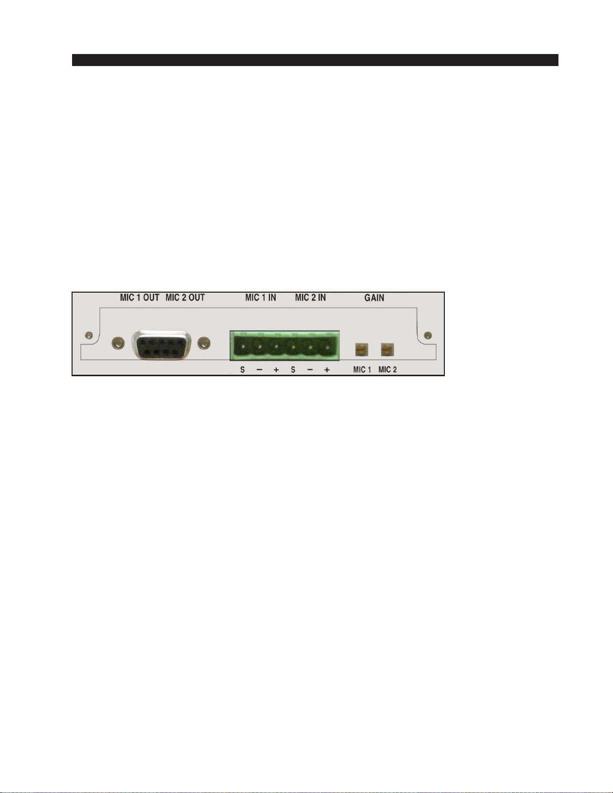
MPW-12 Mic Preamp Connections
MIC 1 and MIC 2 Inputs—6-pin Plug Terminal
All signals are analog mono. The mic input level is normally -50dBu
balanced.
Pin 1 – Mic 1 In SH
Pin 2 – Mic 1 In LO
Pin 3 – Mic 1 In HI
Pin 4 – Mic 2 In SH
Pin 5 – Mic 2 In LO
Pin 6 – Mic 2 In HI
MIC 1 and MIC 2 Outputs—DB-9
All signals are analog mono. The mic output level is normally +4dBu
balanced.
Pin 5 – Mic 1 Out SH
Pin 4 – Mic 1 Out HI
Pin 9 – Mic 1 Out LO
Pin 8 – Mic 2 Out SH
Pin 7 – Mic 2 Out HI
Pin 3 – Mic 2 Out LO

INSTALLATION and POWER
page 1 – 10
W-12 / Sep 2007
ADC-W12 Analog Input Connections—DB-25
Pin 25 – LINE 1 A LT IN SH
Pin 24 – LINE 1 A LT IN HI
Pin 12 – LINE 1 A LT IN LO
Pin 11 – LINE 1 A RT IN SH
Pin 10 – LINE 1 A RT IN HI
Pin 23 – LINE 1 A RT IN LO
Pin 22 – LINE 1 B LT IN SH
Pin 21 – LINE 1 B LT IN HI
Pin 9 – LINE 1 B LT IN LO
Pin 8 – LINE 1 B RT IN SH
Pin 7 – LINE 1 B RT IN HI
Pin 20 – LINE 1 B RT IN LO
Pin 19 – LINE 2 A LT IN SH
Pin 18 – LINE 2 A LT IN HI
Pin 6 – LINE 2 A LT IN LO
Pin 5 – LINE 2 A RT IN SH
Pin 4 – LINE 2 A RT IN HI
Pin 17 – LINE 2 A RT IN LO
Pin 16 – LINE 2 B LT IN SH
Pin 15 – LINE 2 B LT IN HI
Pin 3 – LINE 2 B LT IN LO
Pin 2 – LINE 2 B RT IN SH
Pin 1 – LINE 2 B RT IN HI
Pin 14 – LINE 2 B RT IN LO
SRC-W12 Digital Input Connections—DB-25
Pin 25 – AES 1 A IN SH
Pin 24 – AES 1 A IN HI
Pin 12 – AES 1 A IN LO
Pin 11 – AES 1 B IN SH
Pin 10 – AES 1 B IN HI
Pin 23 – AES 1 B IN LO
Pin 22 – AES 2 A IN SH
Pin 21 – AES 2 A IN HI
Pin 9 – AES 2 A IN LO
Pin 8 – AES 2 B IN SH
Pin 7 – AES 2 B IN HI
Pin 20 – AES 2 B IN LO
Monitor Output Connections—DB-25
Pin 25 – CR LT OUT SH
Pin 24 – CR LT OUT HI
Pin 12 – CR LT OUT LO
Pin 11 – CR RT OUT SH
Pin 10 – CR RT OUT HI
Pin 23 – CR RT OUT LO
INSTALLATION and POWER
page 1 – 11
W-12 / Sep 2007
Pin 22 – ST LT OUT SH
Pin 21 – ST LT OUT HI
Pin 9 – ST LT OUT LO
Pin 8 – ST RT OUT SH
Pin 7 – ST RT OUT HI
Pin 20 – ST RT OUT LO
Pin 19 – CUE LT OUT SH
Pin 18 – CUE LT OUT HI
Pin 6 – CUE LT OUT LO
Pin 5 – CUE RT OUT SH
Pin 4 – CUE RT OUT HI
Pin 17 – CUE RT OUT LO
Pin 16 – HDPN LT OUT SH
Pin 15 – HDPN LT OUT HI
Pin 3 – HDPN LT OUT LO
Pin 2 – HDPN RT OUT SH
Pin 1 – HDPN RT OUT HI
Pin 14 – HDPN RT OUT LO
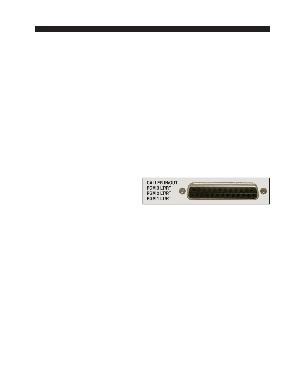
Program Analog Output & Caller Connections—DB-25
Pin 25 – PGM 1 LT OUT SH
Pin 24 – PGM 1 LT OUT HI
Pin 12 – PGM 1 LT OUT LO
Pin 11 – PGM 1 RT OUT SH
Pin 10 – PGM 1 RT OUT HI
Pin 23 – PGM 1 RT OUT LO
Pin 22 – PGM 2 LT OUT SH
Pin 21 – PGM 2 LT OUT HI
Pin 9 – PGM 2 LT OUT LO
Pin 8 – PGM 2 RT OUT SH
Pin 7 – PGM 2 RT OUT HI
Pin 20 – PGM 2 RT OUT LO
Pin 19 – PGM 3 LT OUT SH
Pin 18 – PGM 3 LT OUT HI
Pin 6 – PGM 3 LT OUT LO
Pin 5 – PGM 3 RT OUT SH
Pin 4 – PGM 3 RT OUT HI
Pin 17 – PGM 3 RT OUT LO
Pin 16 – CALLER IN SH
Pin 15 – CALLER IN HI
Pin 3 – CALLER IN LO
Pin 2 – CALLER OUT SH
Pin 1 – CALLER OUT HI
Pin 14 – CALLER OUT LO
Table of contents
Other AudioArts Engineering Dj Equipment manuals


