AudioArts Engineering RD-12 User manual

RD-12 Digital Audio
Console
TECHNICAL MANUAL
March 1999

R-16 / Dec 1997
RD-12 Digital Audio Console Technical Manual - 1st Edition
©1999 Audioarts®Engineering*
AUDIOARTS ENGINEERING
600 Industrial Drive
New Bern, North Carolina 28562
252-638-7000
*a division of Wheatstone Corporation
RD-12 / March 1999

ATTENTION
READ ME!
RD-12 / March 99
Attention!
This console contains static sensitive devices:
Normal precautions against static discharge should be observed when
handling individual modules. In particular, modules being packed for shipping
for return or repair must be packed in special static protection bags before
packaging. Damage caused by static discharge may not be covered under
warranty.
Replacing Modules in a Powered-up Console:
While in an emergency situation it is possible to remove and insert modules
on a powered-up console, Wheatstone does not recommend this procedure.
Whenever possible it is best to power down the console first before removing
or replacing modules.
However, if you find you must proceed with this operation, then be sure to
take the following precaution:
When re-inserting a module, take care to replug it squarely into its
mainframe connector socket, so all edgecard fingers make contact
simultaneously. In other words, the gold-plated bus connector fingers on the
bottom edge of the module's printed circuit board must be inserted squarely
(i.e., perpendicular) to the mating socket on the bottom pan of the console
mainframe. The intent is to prevent a situation where one of the module's
power pins makes significant contact before the others. (Naturally, this
same precaution must be taken when using extenders.)
If the above instructions are followed the procedure should be routine; if they
are not, you could run the risk of damaging the console's logic chips.
Again, to avoid ANY possibility of this damage, whenever possible we
strongly recommend powering down the consolebefore replacing any modules.
!
RR
RR
READEAD
EADEAD
EAD MM
MM
M
EE
EE
E!!
!!
!
May 2000
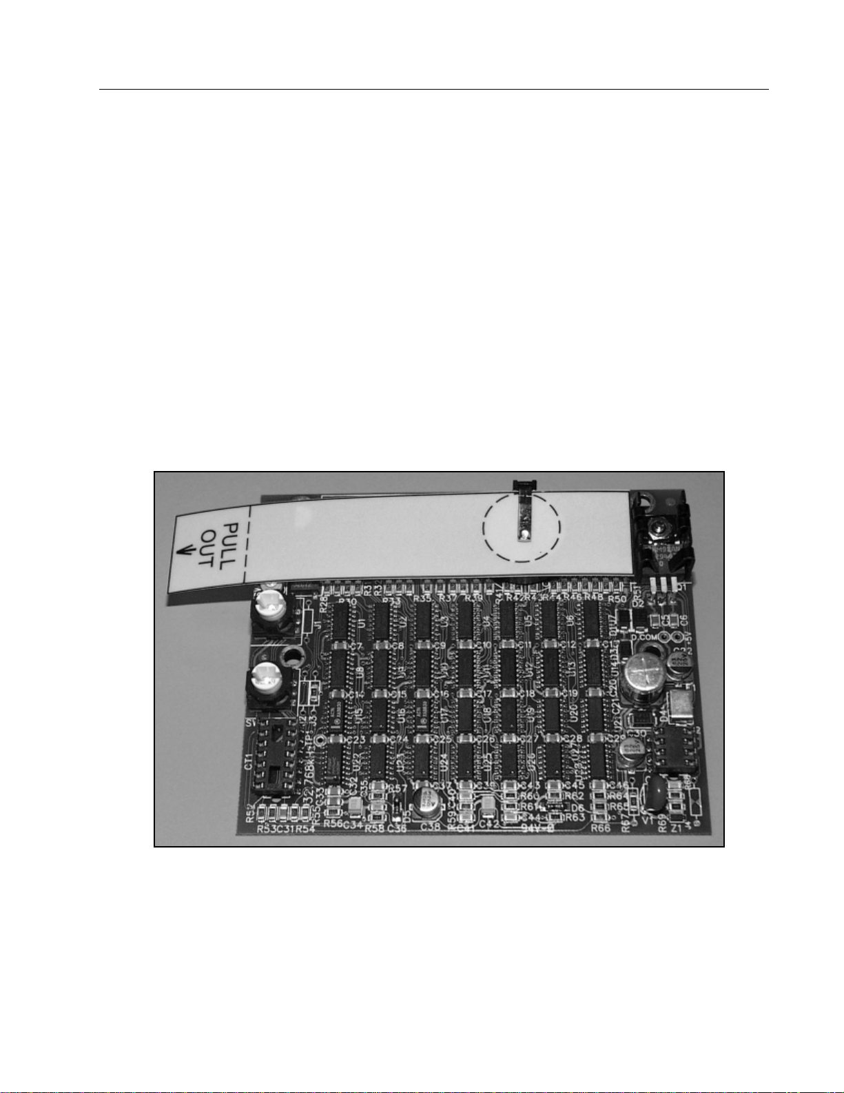
Console Clock Battery Backup
Attention!
Console Clock Display Card
To activate battery backup of the console’s clock simply pull out the yellow
strip from the clock display card, that is mounted on the inside of console
meterbridge, as shown on the picture below.

Your Audioarts RD-12 audio console is equipped with two
"module extractor tools" which are mounted underneath the
console armrest, to the far right (just above and to the left of
the righthand mainframe headphone jack).
Main module faceplates are held into the console mainframe by two
mounting screws (top and bottom). When removed the screws leave
specially threaded holes that accept the two extractor tools.
To remove a module faceplate from the mainframe:
Remove the front top and bottom mounting screws. Remove the extractor
tools from underneath the armrest, and screw each tool into a module
faceplate mounting hole. Use only four or five turns (do not over-insert; you
may damagethe threaded mainframe hole underneath).Using the extractor
tools as handles, pull the module straight up out of the mainframe.
ModuleRemovalTools
E X T R A C T O R T O O L S

page Contents – 1
RD-12 / March 99
CONTENTS
RD-12 Technical Manual
Table of Contents
Chapter 1 – Installation and Power
CountertopMounting................................................................. 1-2
Clearances.............................................................................................................. 1-2
System Ground .......................................................................... 1-2
Power Supplies .......................................................................... 1-4
Power Supply Cable Pinout.................................................................................... 1-5
The VU/Timer Cable ............................................................................................... 1-6
Energizing ............................................................................................................... 1-6
Audio and Control Wiring.......................................................... 1-7
ConnectionProcedures .......................................................................................... 1-7
Insert Points............................................................................................................ 1-7
UnbalancedConnections ....................................................................................... 1-7
Hand crimp tool wiring instructions......................................................................... 1-8
Chapter 2 - Mono Mic Inputs
Module Overview........................................................................ 2-2
Internal Programming Options ................................................. 2-3
Insert Bypass .......................................................................................................... 2-3
Phantom Power ...................................................................................................... 2-3
Mutes ...................................................................................................................... 2-3
Timer Restart .......................................................................................................... 2-3
Tallies...................................................................................................................... 2-4
Utility Bus Pre-Fader .............................................................................................. 2-4
Talkback.................................................................................................................. 2-4
Superphone Output Assign .................................................................................... 2-5
Hook-ups..................................................................................... 2-5
AUDIO CONNECTIONS......................................................................................... 2-5
CONTROL CONNECTIONS................................................................................... 2-6
Remote ON & OFF ................................................................................................. 2-6
Talkback to Control Room ...................................................................................... 2-6
On Tally................................................................................................................... 2-6
Off Tally................................................................................................................... 2-7
RD-12 / Nov 03

page Contents – 2
RD-12 / March 99
CONTENTS
Chapter 3 - Stereo Line Inputs
Module Overview...........................................................................3-2
Internal Programming Options ....................................................3-3
Mutes ........................................................................................................................ 3-3
Timer Restart ............................................................................................................ 3-3
Cue Dropout.............................................................................................................. 3-3
Local/Ready .............................................................................................................. 3-3
Utility Bus Pre-Fader ................................................................................................ 3-4
Tallies........................................................................................................................ 3-4
Superphone Output Assign ...................................................................................... 3-4
Remote On/OFF — Constant vs. Pulse ................................................................... 3-4
Remote START/STOP - Normal vs. EFS................................................................. 3-5
Hook-ups........................................................................................3-5
ANALOG AUDIO CONNECTIONS........................................................................... 3-5
DIGITAL AUDIO CONNECTIONS............................................................................ 3-6
CONTROL CONNECTIONS..................................................................................... 3-6
Remote ON & OFF ................................................................................................... 3-6
On Tally..................................................................................................................... 3-7
External START & STOP ......................................................................................... 3-7
Ready........................................................................................................................ 3-7
Typical Hook-Up Diagram ........................................................................................ 3-8
Chapter 4 - Output Modules
Module Overview...........................................................................4-2
Internal Programming Options ....................................................4-3
Insert Bypass ............................................................................................................ 4-3
Hook-ups........................................................................................4-3
Master Output Module 1 (PGM)
AMP A, B Connectors — Analog Audio............................................................. 4-3
AMP D Connector — Digital Outputs ................................................................ 4-4
Master Output Module 2 (AUD and UTIL)
AMP A, B Connectors — Analog Audio............................................................. 4-4
AMP D Connector — Digital Outputs ................................................................ 4-4
Chapter 5 - Control Room Module
Module Overview...........................................................................5-2
Internal Programming Options ....................................................5-3
Cue Interrupt............................................................................................................. 5-3
Cue Mute .................................................................................................................. 5-3
Mono Cue ................................................................................................................. 5-3
Hook-ups........................................................................................5-4
AMP A, B Connectors — AUDIO.............................................................................. 5-4
AMP B Connector — CONTROL.............................................................................. 5-4
RD-12 / Jan 00

page Contents – 3
RD-12 / March 99
CONTENTS
On-Air Tally......................................................................................................... 5-4
AMP D Connector — AUDIO.................................................................................... 5-5
Chapter 6 - Studio Control Module
Module Overview...........................................................................6-2
Internal Programming Options ....................................................6-3
External Talkback Mute/Dim..................................................................................... 6-3
Studio Dim ................................................................................................................ 6-3
Hook-ups........................................................................................6-4
AMP A, B Connectors — AUDIO.............................................................................. 6-4
AMP B Connector — CONTROL.............................................................................. 6-4
Tally 2 and Tally 3 ............................................................................................... 6-4
AMP C, D Connectors — AUDIO ............................................................................. 6-5
Chapter 7 - Meter Output Module
Module Overview...........................................................................7-2
Internal Programming Options ....................................................7-2
Hook-ups........................................................................................7-2
Chapter 8 - CPU and DSP Modules
Module Overview...........................................................................8-2
AES Clock Sync........................................................................................................ 8-2
CPU-5 Display .......................................................................................................... 8-2
Chapter 9 - Superphone Input Module; optional
Module Overview...........................................................................9-2
Caller Set-Ups .......................................................................................................... 9-2
Automatic Features................................................................................................... 9-3
Inputs and Outputs ................................................................................................... 9-3
Internal Programming Options - Main PCB ................................9-4
Output Assign Switch Enable ................................................................................... 9-4
Mutes ........................................................................................................................ 9-4
Timer Restart ............................................................................................................ 9-4
Tallies........................................................................................................................ 9-4
Cue Dropout.............................................................................................................. 9-5
Gain Trimpots ........................................................................................................... 9-5
Internal Programming Options - Piggyback PCB ......................9-5
External In................................................................................................................. 9-5
Cue Pre/Post ............................................................................................................ 9-5
Gain Trimpots ........................................................................................................... 9-5
Hook-ups........................................................................................9-6

page Contents – 4
RD-12 / March 99
CONTENTS
AUDIO CONNECTIONS (AMP A, B)........................................................................ 9-6
AUDIO and CONTROL CONNECTIONS (AMP C, D) ............................................. 9-6
Chapter 10 - Line Preselector (Analog); optional
Overview .......................................................................................10-2
Internal Programming Options ...................................................10-2
Hook-ups.......................................................................................10-3
Audio Inputs ............................................................................................................. 10-3
Outputs .................................................................................................................... 10-4
Chapter 11 - Line Preselector (Digital/Analog); optional
Overview .......................................................................................11-2
Internal Programming Options ...................................................11-2
LSR-500 (drawing)........................................................................11-3
Hook-ups – LSD-5 ........................................................................11-3
Control Connections ................................................................................................ 11-3
Power Connections.................................................................................................. 11-4
Hook-ups – LSR-500 ....................................................................11-4
Analog Audio Inputs................................................................................................. 11-4
Digital Audio Inputs.................................................................................................. 11-5
Analog Outputs ........................................................................................................ 11-6
Digital Outputs ......................................................................................................... 11-6
DB Connector Pinout Drawing (LSR-500)..................................11-7
Chapter 12 - Intercom Module; optional
Overview .......................................................................................12-2
Internal Programming Options ...................................................12-2
Cue Enable .............................................................................................................. 12-3
Input Signal .............................................................................................................. 12-3
Power for various ICMs ........................................................................................... 12-3
Station Select........................................................................................................... 12-3
Hook-ups.......................................................................................12-4
AMP B Connector - AUDIO ..................................................................................... 12-4
AMP A, B Connectors - CONTROL......................................................................... 12-4
AMP D Connector - AUDIO ..................................................................................... 12-5
AMP C, D Connectors - CONTROL ........................................................................ 12-5
Chapter 13 - Tape Remote Module; optional
Overview .......................................................................................13-2
Hook-ups.......................................................................................13-3
RD-12 / June 00

page Contents – 5
RD-12 / March 99
CONTENTS
START/STOP Function Control I/O...................................................................... 13-3
Full-Function Control I/O ...................................................................................... 13-5
Chapter 14 - Meterbridge and Clock
Overview ................................................................................... 14-2
Replacement Parts................................................................... 14-2
Clock ......................................................................................... 14-2
Controls................................................................................................................. 14-2
Setting the Time.................................................................................................... 14-3
Battery Backup ..................................................................................................... 14-3
Operational Modes ............................................................................................... 14-3
Chapter 15 - I/O Schematic Drawings
Mono Mic Input Module Schematic (MMD-500).................................................. 15-2
Stereo Line Input Module Schematic (SLD-500)................................................. 15-4
Digital Stereo Line Input Card Schematic (SRC-500) ......................................... 15-5
Analog Stereo Line Input Card Schematic (SLADC-600) ................................... 15-6
Output Module Schematic (OMD-500) ................................................................ 15-7
Control Room Module Schematic (CRD-500) ..................................................... 15-8
Studio Control Module Schematic (SCD-500)................................................... 15-11
Digital Superphone I/O Card Schematic (SPND-500) ....................................... 15-13
Analog Superphone I/O Card Schematic (SPNA-600)....................................... 15-14
Digital/Audio Line Select Rackmount Schematic (LSR-500) ............................ 15-15
Tape Remote Module Schematic (TRD-500)..................................................... 15-17
Intercom Module Schematic (ICMD-500) ........................................................... 15-18
Appendix - Replacement Parts List
Replacement Parts List .............................................................A-2
RD-12 / Aug 00

I N S T A L L A T I O N a nd P OWER
page 1 – 1
RD-12 / March 99
Installation and Power
Chapter Contents
Countertop Mounting................................................................. 1-2
Clearances..........................................................................................................1-2
System Ground .......................................................................... 1-2
Power Supplies .......................................................................... 1-4
Power Supply Cable Pinout................................................................................1-5
The VU/Timer Cable...........................................................................................1-6
Energizing...........................................................................................................1-6
Audio and Control Wiring.......................................................... 1-7
Connection Procedures ...................................................................................... 1-7
Insert Points........................................................................................................1-7
Unbalanced Connections ................................................................................... 1-7
Hand crimp tool wiring instructions.....................................................................1-8
RD-12 / Nov 03

I N S T A L L A T I O N a nd P OWER
page 1 – 2
RD-12 / March 99
Installation and Power
Countertop Mounting
The RD digital audio console is designed for countertop drop-in
mounting. Console placement should avoid proximity to any electro-
magnetic fields, such as large power transformers, motors, and fluores-
cent lighting fixtures. The required cut-out width is 31 5/8” for RD-12
or 43 5/8” for RD-20, and cut-out front-to-back dimension is 18 3/8”.
The front of the console will extend approximately one inch forward of
the cut-out. The console’s wooden sidepieces will extend about 7/8” on
either side of the cut-out width.
Clearances
Note the two module extractor tools (black thumbwheel screws)
mounted in the front surface of console’s lower mainframe pan (just
above and to the left of the righthand headphone jack). These must be
removed before lowering the console into its cutout!
Once in place the console mainframe pan will extend approxi-
mately 5 1/2 inches below the countertop surface. Note the hinged
meterbridge will require 10 1/2” above the countertop surface to open
freely. When fully open the meterbridge will extend 5 1/2” behind the
rear line of the cut-out. When closed, the meterbridge will extend
2 1/2” behind this rear cut-out line and 6 1/4” above the countertop
surface.
Do not connect the RD console to its power supply (and do not
connect the power supply to the AC power line) until instructed to
do so.
System Ground
The first step is to ground the console.
Note that as supplied from the factory, console rackmount power
supply common, audio ground, and the RD mainframe are connected
together at the console, but are NOT connected to electrical ground and
the chassis of the power supply. Safety requirements dictate that a
positive connection from the console mainframe to electrical ground be
made in the completed installation. Use one of the grounding lugs on
the bottom of the mainframe to establish your system ground. The
!
RD / Oct 00

I N S T A L L A T I O N a nd P OWER
page 1 – 3
RD-12 / March 99
CONSOLE
2-TRACK
MULTI-TRACK
AC BREAKER
BOX
DEVICE 1
DEVICE 2
DEVICE N
CONSOLE POWER SUPPLY
CONTROL ROOM POWER AMP
STUDIO POWER AMP
OTHER
POWER COMPANY
EARTH GROUND
HEAVY
(#4 or #6)
COPPER
WIRE
HIGH POWER
EQUIPMENT RACK
COPPER ROD
SOIL 3-wire ground or separate wire run from chassis
EFFECTS RACK
MIC PANEL
GND
TYPICAL SYSTEM
GROUNDING SCHEME
etc.
3–5 ft.
Tie the console ground lug
terminal strip to the system
earth ground. Tie every piece
of equipment in the entire
audio system to the console
ground lug terminal strip.
grounding lug terminal strip may be found at the rear of the console,
along the bottom edge of the mainframe pan directly under the
rightmost mainframe slots (to the lower left if you are looking at the rear
of the console).
The system ground serves two important purposes:
(1) It provides a zero signal reference point for the entire audio system;
(2) It assures safety from electrical shock.
There exist two terms that one encounters in a discussion of ground:
(A) EARTH GROUND, which is usually a heavy copper rod driven into the
soil adjacent to the building (around 6 feet down) or a connection to the copper
water pipes leading into the building. Either is acceptable (unless, of course,
the water pipe is made of plastic).
(B) THE POWER COMPANY EARTH CONDUCTOR that enters the
building at the power line breaker box; this conductor should be (and is often
by code) tied to the above-mentioned earth ground at one point. This point is
the SYSTEM EARTH GROUND.
RD / Oct 00

I N S T A L L A T I O N a nd P OWER
page 1 – 4
RD-12 / March 99
TIE THE CONSOLE GROUND LUG TERMINAL STRIP TO THE
SYSTEM EARTH GROUND. TIE EVERY PIECE OF EQUIPMENT IN
THE ENTIRE AUDIO SYSTEM TO THE CONSOLE GROUND LUG
TERMINAL STRIP. If the system earth ground point is inaccessible, tie
the console ground terminal strip to the power company earth conductor
at the main breaker box (see drawing "Typical Grounding Scheme" on
previous page).
Each piece of equipment should be connected by its own ground wire
(usually the round third pin on the AC cord). This means that every AC
outlet must have a separate conductor run to the console ground lug
terminal strip; the outlets cannot be daisy-chained as is normally encoun-
tered in commercial and residential AC systems. Any equipment not
supplied with 3-wire AC cables must have individual ground wires (16
gauge or larger) connected to their chassis grounds and then run to the
console ground lug terminal strip.
Further Grounding Details
Check all equipment to be absolutely certain that each unit is power
transformer isolated from the AC mains to prevent safety hazards.
It is assumed that in each piece of audio equipment the audio ground
and the chassis are tied together at some point. Any piece of equipment
lacking a grounded chassis is likely to be prone to interference problems.
Locate all unbalanced audio equipment in the same rack if possible, to
minimize chassis ground potential differences. It may also be helpful to
insulate each piece of unbalanced equipment from its mounting rails in the
rack by means of nylon 10-32 screws and insulating washers between rails
and faceplates.
Once the system is properly grounded, proceed with the console
power supply installation and connection (next section).
Power Supplies
The RD console is powered by an Audioarts Model SPS-180R
rackmount power supply. This unit occupies two 19” wide rack spaces
(total height 3-1/2”). Convection cooled, it requires ample ventilation
space above and below it. The SPS-180R generates a lot of heat in the
course of normal operation — do not mount heat sensitive devices in the
same rack cabinet.
Note the power supply should be mounted in an equipment rack within
fifteen feet of the console (but no closer than 3 feet). Avoid locating any
high gain equipment (such as phono preamps, tape recorders, etc.) too near
the rackmount supplies, to avoid magnetic interference into that equip-
ment.
This power supply contains high voltage circuits that are hazardous and
potentially harmful.Under no circumstances should the metal cover be
removed! If you have a problem with the power supply, the SPS-180R unit
must be returned to Audioarts for repair.
RD-12 / Nov 03
I N S T A L L A T I O N a nd P OWER
page 1 – 5
RD-12 / March 99
Once the supply is rackmounted, it should be connected to the console
using the factory supplied cable. The console’s power supply connector is
located at the rear of the console, at the right end of the meterbridge bottom
pan. Note that the power supply cable’s 10-pin female connector has to be
rotated until its locating pins match the male connectors on the console. Do
not force a connector on; it attaches easily when properly aligned. Connect
the cable first to the console, then to the rear of the rackmount power
supply.
RD / Nov 2003
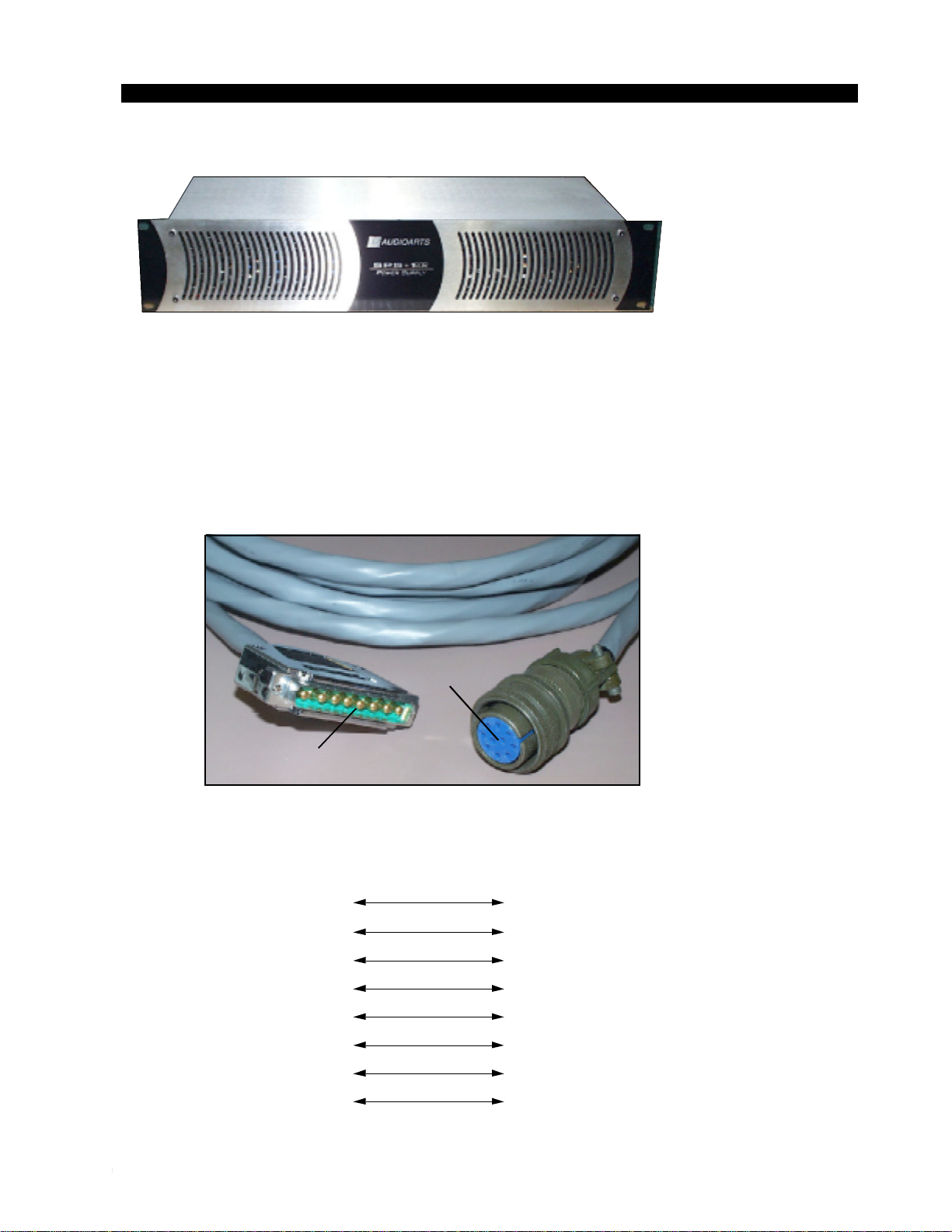
Front view of the SPS-180R
rackmount power supply
Power Supply
Console
End
End
E
D
F
H
PIN
1
2
3
4
PIN
8-pin Connector
Male
Power Supply End 10-pin Connector
Female
Console End
G
A
C
B
5
VIO
GRN
BRN
YEL
ORG
BLK
BLU
RED
PS Cable Pinout
VIO
GRN
BRN
YEL
ORG
Phantom
6
BLK
7
BLU
8RED
Digital Ground
Digital Ground
Digital+
Digital+
Analog Ground
-V in
+V in

I N S T A L L A T I O N a nd P OWER
page 1 – 6
RD-12 / March 99
Note that each power supply is fitted with a 3-wire grounded AC cord
that should be plugged into a "clean" AC power source, that is, an AC
source that feeds only the control room audio gear. This source should be
a separate feed from those powering lighting, air-conditioning, or any
other non-audio machinery. The third pin ground wire of the AC source
should be tied to the central system ground point. Note that while the AC
power cord ground wire terminates at the power supply chassis, it does
NOT connect to the RD console common; the console itself must be
grounded separately. (See previous section, "System Ground".)
The VU/Timer Cable
Connections from the MOD-5 Meter Output Module to the Meterbridge
for VU meter and timer signals are made through a special cable that ships
with the console. This cable has a DB-25 at the one end and two 12-pin
AMP type connectors at the other end. Connect the DB-25 connector to
the matching DB-25 connector on the underside of the Meterbridge at the
back of the console. Connect the two AMP type connectors to connectors
A and B on the bottom of the frame at the slot that contains the MOD-5
module (the connectors on the cable are labeled “A” and “B”).
Energizing
Assuming the RD console mainframe is properly placed and grounded,
and its SPS-180R power supply correctly rackmounted and connected to
the console, you may now energize the SPS-180R rackmount power
supply by plugging it into the AC mains. The console's individual module
switches will assume factory default settings.
Note: To de-energize the console, unplug the rackmount power
supply’s AC cord from the AC mains. Never de-energize the console by
disconnecting the cable that connects the console and power supply
together.
Once you have verified proper power-up, unplug the rackmount power
suppliesto de-energize theconsole. Youmay nowproceed towire upaudio
and control connections.
RD-12 / Nov 03
The power feed recom-
mended in the text is of-
ten installed and referred
to in studios as an “iso-
lated AC ground” outlet.
It is usually orange in
color.

I N S T A L L A T I O N a nd P OWER
page 1 – 7
RD-12 / March 99
Audio and Control Wiring
All audio and control I/O connections to the RD-12 console are made
through 12-pin AMP type connectors. The supplied 12-pin connectors use
crimp type pins. A crimp tool must be used, and an extraction tool is handy to
remove pins that have been inserted in the wrong connector block hole, or if
rewiring or wiring repair is needed in the future (see “Hand crimp tool wiring
instructions” on pages 1-8, 1-9). Always be careful to double check pin
numbering on the connector block and the wiring diagram before inserting the
pin in the block.
Connection Procedures
As supplied from the factory, the console requires no logic connections to
function. Therefore an orderly installation begins with the audio wiring. Note
that this manual is organized by module type (inputs, outputs, monitor
modules, etc.); each chapter contains detailed wiring instructions for its
module type. Proceed through the manual, chapter by chapter, until all modules
have been wired to suit your particular installation requirements. Once proper
audio operation is verified, go back to each individual chapter and proceed with
control wiring.
Insert Points
Certain module signals have insert patch points in their signal chains to
allow outboard audio processing. These include MONO MIC INPUTS
(MMD-5) and OUTPUT MODULES (OMD-5).
Normally these points are internally bridged at the factory (via PCB-
mounted programming switches) prior to shipment. If you intend to use
outboard signal loops at these points, you must reprogram these switches. See
pages 2-3 (mic inputs) and 4-3 (output modules) for details.
Unbalanced Connections (analog audio)
INPUTS — Wire to the console with typical shielded two conductor cable
(like Belden 9451), just as if you were connecting a balanced source. At the
unbalanced source machine’s output, connect the black wire (LOW) to the
shield. If the machine has a -10 dBu output, don’t hesitate to turn module input
gain as high as is needed.
OUTPUTS — RD consoles use a balanced output circuit which behaves
exactly like the secondary of a high-quality transformer, with no center tap—
this output is both balanced and floating. Either the HIGH or LOW side of the
output should be strapped to ground, with the output taken from the other side.
(Normally you’d strap LOW to ground, and take HIGH to feed your unbal-
anced equipment.)

I N S T A L L A T I O N a nd P OWER
page 1 – 8
RD-12 / March 99
HAND CRIMP TOOL WIRING INSTRUCTIONS
The supplied hand crimping tool (W/S#850067) is used for all I/O wiring con-
nections to and from the console. It is to be used with the supplied pin (figure 1)
intended for 22"-28" gauge wire.
1) Strip wire approximately 3/16" (insert in
proper wire stripper, rotate one half turn, and
pull insulation off wire).
2) Leaving wire aside for the moment, with
crimping tool fully open (engraved side toward
you) bring a terminal into position from the
unmarked side of the tool. Place the conductor
tabs (inner set as shown in figure 1) on the
"18-22" or "24-30" (depending on the wire) an-
vil (slightly curved surface) so that the circular
portion of the tabs rests in the curved surface
of the anvil and the two tabs face up into the
walls of the female jaw. The insulation tabs will
be flush with the top of the tool (figure 2).
3) Close tool very slightly, only to the point
of holding the terminal in position (figure 2).
4) Insert wire into terminal until wire insu-
lation is stopped by conductor tabs (figure 3).
CRIMP by squeezing handles until jaws are fully
closed (figure 4).
5) If there is an insertion error or if a circuit
change is needed, you'll need to use an extrac-
tor tool to remove terminals (see next page).
Note that metallized plastic hoods for each
connector are also supplied with the console.
(1) Pin crimp terminal
CONDUCTOR
TABS
INSULATION
TABS
INSULATION
STOPS HERE
(2) The terminal conductor tabs (pointing UP) are
placed in anvil 18-22; the terminal's insulation tabs
extend in front towards the camera.
(3) The stripped wire is placed into the terminal and
crimped. Note the wire's insulation must stop just
short of the conductor tabs (detail)
(4) Final step: jaws fully closed; the insulation tabs
have been crimped.
RD-12 / Jun 2004

INSTALLATION and POWER
page 1 – 9
RD-12 / March 99RD-12 / Jun 2004
STEP 1.
Push wire attached to pin terminal, to
be removed, forward to free pin
terminal locking flanges from the
Nylon Connector Housing.
STEP 2.
Place extractor tip over pin
terminal to be removed. Press
handle portion of extractor in
downward motion until tip rests
upon Nylon Housing.
STEP 3.
Push ball at top of extractor
down toward pin terminal; pin
terminal will extract from Nylon
Housing.
EXTRACTOR PIN INSTRUCTIONS
If you should accidentally insert a crimp terminal pin into the wrong socket, the
supplied pin extractor tool (Waldom P/N W-HT-2023) will let you correct your mistake
without having to sacrifice a connector.

M O N O M I C I N P U T
page 2 – 1
RD-12 / March 99
Mono Mic Input (MMD-5)
Chapter Contents
Module Overview........................................................................ 2-2
Internal Programming Options ................................................. 2-3
Insert Bypass..........................................................................................................2-3
Phantom Power ...................................................................................................... 2-3
Mutes ......................................................................................................................2-3
Timer Restart ..........................................................................................................2-3
Tallies......................................................................................................................2-4
Utility Bus Pre-Fader .............................................................................................. 2-4
Talkback..................................................................................................................2-4
Superphone Output Assign ....................................................................................2-5
Hook-ups..................................................................................... 2-5
AUDIO CONNECTIONS.........................................................................................2-5
CONTROL CONNECTIONS...................................................................................2-6
Remote ON & OFF .................................................................................................2-6
Talkback to Control Room...................................................................................... 2-6
On Tally...................................................................................................................2-6
Off Tally...................................................................................................................2-7
Table of contents
Other AudioArts Engineering Dj Equipment manuals

Popular Dj Equipment manuals by other brands

Fun Generation
Fun Generation USB PartyPar 6 RGB user manual

Equinox Systems
Equinox Systems Twin Shot MKII Electric Confetti Launcher user manual

Chauvet DJ
Chauvet DJ COLORband Q4 IP Quick reference guide

American DJ
American DJ Inno Roll LED User instructions

Lightmaxx
Lightmaxx GALAXY ARC Series user manual

PIONEER DJ
PIONEER DJ SERATO DDJ-REV7 instruction manual


