Audiocenter Artist T88D User manual

Artist T88D/T88
User’s Manual
Revision A0-2021-11
Audio Matrix

Important Precautions
1.Save the carton and packing materials even if the equipment
is arrived in good condition. Should you ever need to ship the
device (back to the factory), you can only use the original
manufacturer’s packaging.
9.Have gain controls on processors turned down during
power-up to prevent amplifier or speaker damage if there
are high signal levels at the inputs.
2.Read all documentation before operating your equipment.
Retain all documentation for future reference.
4.Do not spill water or other liquids into or on the unit, or
operate the unit while standing in liquid.
This symbol is used to alert the operator to follow
important operating and precautions detailed in documentation.
This symbol is used to warn operators that uninsulated“dangerous voltages” are
present within the equipment that may pose a risk of electric shock.
5.Make sure power outlets conform to the power
requirements listed on the back of the unit.
6.Do not use the unit if the electrical power cord is frayed or
broken. The power supply cords should be routed so that they
are not likely to be walked on or pinched by items placed upon
or against them, paying particular attention to cords and plugs,
convenience receptacles, and the point where they exit from
the appliance.
7.Always operate the unit with the AC ground wire connected
to the electrical system ground. Precautions should be taken
so that the means of grounding of a piece of equipment is not
defeated.
8.Mains voltage must be correct and same as that printed
on the rear of the unit. Damage caused by connection to
improper AC voltage is not covered by any warranty.
15.Do not connect the inputs / outputs of processor or
consoles to any other voltage source, such as a battery,
mainssource, or power supply, regardless of whether the
processor or console is turned on or off.
18.To obtain service, contact your nearest AUDIOCENTER
service centre, distributor or dealer.
3.Follow all instructions printed on unit chassis for proper
operation.
11.Never hold a power switch in the “ON” position if it won’t
staythere itself.
10.Power down and disconnect units from mains voltage
beforemaking connections.
13.Do not block fan intake or exhaust ports. Do not operate
equipment on a surface or in an environment which may impede
the normal flow of air around the unit, such as a bed, rug, weather
sheet, carpet, or completely enclosed rack. If the unit is used in an
extremely dusty or smoky environment, the unit should be
periodically “blown free” of foreign matter.
12.Do not use the unit near stoves,heat registers,radiators,or
other heat producing devices.
14.Do not remove the cover. Removing the cover will
expose you to potentially dangerous voltages. There are
no user serviceable parts inside.
16.Non-use periods: The power cord of equipment should
beunplugged from the outlet when left unused for a long
period of time.
17.Service information: Equipment should be serviced by
qualified service personnel when:
A.Thepowersupplycordortheplughasbeendamaged;
B.Objectshavefallen,orliquidhasbeenspilledintothe
equipment;
C.Theequipmenthasbeenexposedtorain;
D.Theequipmentdoesnotappeartooperatenormally,or
exhibitsamarkedchangeinperformance;
E.Theequipmenthasbeendropped,ortheenclosure
damaged.

2
2
2
3
3
4
5
6
7
11
21
23
30
37
20
Table of Contents
Introduction
Unpacking
Installation
Front Panel
Rear & Side Panel
Introduction of Front & Rear Panel Function
Software Operation Instructions
Software Connection
Software Interface
Function Interface
Preset Management
Camera Tracking
GPIO and Central Control Instruction
Appendix 1 Common Central Control Protocol Instructions
Appendix 2 Specifications
1
Audio Matrix

2
Wall controller
Introduction
Congratulations on your ownership of a new Artist Audio Matrix , and thank you for your confidence in AUDIOCENTER products.
You are among the growing number of audio professionals who have made AUDIOCENTER one of the world’s leading suppliers
of professional and commercial/industrial audio systems.
For your safety, please read the Important Precautions section before installing and operating the Audio Matrix, and please take
some time to read this manual so that you can make full use of the Audio Matrix.
In order to maintain strict quality assurance standards, all Artist Audio Matrix are built in AUDIOCENTER’s state-of-the-art
manufacturing faculty. Internal components are the finest available,and key sub assemblies are pre-tested before final assembly.
Finally, each power Audio Matrix is “burned in” and thoroughly tested (using audio precision test equipment) before shipping. You
can depend on consistent and stable performance even when your Artist Audio Matrix is subject to punishing extremes in the
most demanding fixed or mobile sound reinforcement applications.
Work Seamlessly with Artist speakers and power amplifiers, providing a variety of classical
speaker presets to quickly establish a complete sound system
All functions can be configured through Windows system, supporting networking, joint debugging
and remote control of multiple devices
24 bit AD/DA conversion, 96KHz sampling rate, 10Hz ~ 28KHz bandwidth, over
116dB dynamic range
Built-in camera tracking function to control the camera by sound
GPIO programmable connector
Unpacking
Please inspect the audio matrix carefully immediately after unpacking. If you find any damage, notify your supplier /dealer
immediately. Only the shipper may file a damage claim with the carrier for damage incurred during shipping. Be sure to save
the carton and all packing materials for the carrier’s inspection. If you ever need to ship the unit back to AUDIOCENTER or an
authorized service center, you should use only the original manufacturer’s packaging.
Installation
Artist T88D/T88 is one-rack-space high. Four front-panel mounting holes are provided on each audio matrix. All mount in standard
19-inch racks.
Wallcontroller Mobile
phone The tablet Laptop computer
Audio Matrix
Artist T88D/T88 is a powerful8-in-8-out audio matrix that supports 8 analog audio inputs and 8 analog audio output. Artist T88D
also supports 4 * 4 Dante network audio input and output. Diverse I/O options provide you with the flexibility required to integrate
into the system. It can meet the control and audio processing for various places.
8 analog audio inputs, 8 analog audio outputs, Artist T88D supports 4 * 4 Dante network
audio input and output
With both microphone input and line input, with 48V phantom power
In built with functions of AFC, auto mixing, matrix mixing, equalizer, crossover, limiter by
DSP to deliver clear sound dynamic
USB drive-free automatic connection software, open RS-232, RS-485 protocol to achieve
third-party control, support TCP/IP remote control
Through the computer software BrainCore Net of the Windows system, all devices in the local area can be controlled remotely,
and all the parameters of the Audio Matrix can be effectively controlled. Through the joint debugging function, multiple devices of
the same model can be debugged. Part of the function control can also be achieved through the wall controller and the mobile
APP (Android). With the scene preset function, users can directly use the wall controller or intelligent central control to achieve
scene calling, volume adjustment and other functions.
Artist T88D
Artist T88
Artist T88
3
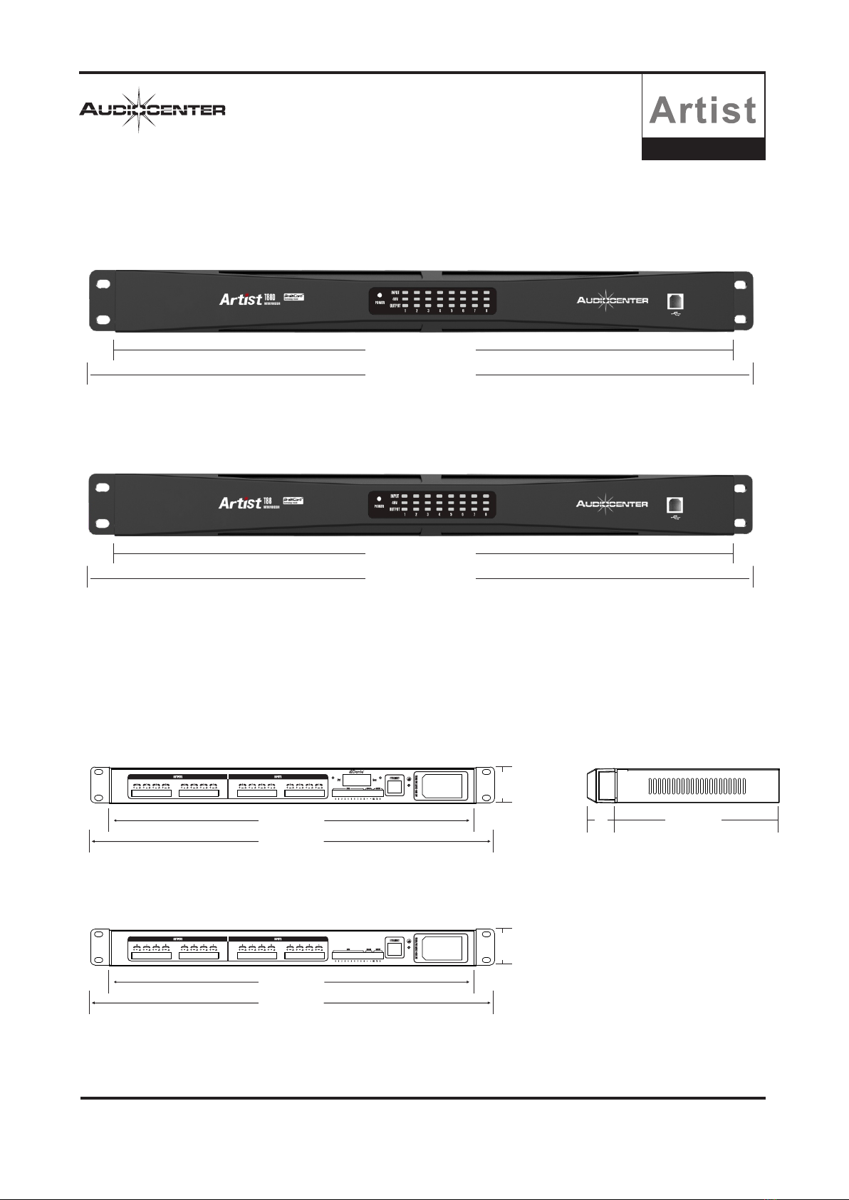
Artist T88D
484mm
439mm
44mm
484mm
439mm
44mm
Front Panel
Rear & Side Panel
Audio Matrix
484mm
439mm
484mm
439mm
210mm35

4
5mm x 20mm/3A/250V
Artist T88D Introduction of Front & Rear Panel Function
Artist T88 Introduction of Front & Rear Panel Function
1.USB port
The computer control software can be connected through USB port.
2.Power LED
The white light indicates that AC power is connected and the processor
is turned on.
3.Input LED
The blue light indicates that the channel has signal input.
4.48V phantom power LED
The yellow light indicates that 48V phantom power is turned on,
which can be turned on or off by computer control software.
5.Output LED
The blue light indicates that the channel has signal output.
6.Rack mounting ears
Two front panel mounting holes are provided on each mounting ear.
7.8-channel analog output
Euro-block connector, balanced output
8.8-channel analog input
Euro-block connector, balanced input
9.Dante audio transmission interface
2 * RJ45 interface, standard CAT5 or CAT6 cable connection, can be
configured as daisy chain connection (up to 8 devices).
10.GPIO interface
GPIO control extension
11.RS 485 interface
It can be used as central control, panel control,
camera tracking and expansion interface.
12.RS 232 interface
It can be used as central control, panel control,
camera tracking and expansion interface.
13.ETHERNET computer control interface
Rj45 interface, based on TCP / IP protocol, standard
CAT5 or CAT6 network cable connection.
14.Grounding terminal
15.Power supply socket
Connected via standard IEC plug
16.Fuse
17.Power switch
When the processor is not in use, please keep its
power switch off.
Audio Matrix

5
Software operation instructions
“BrainCoreNet” is a software for users to quickly interact with the parameters of one or more devices. Configuration
parameters of the device can be stored in the disk file. It provides a very convenient means for the preset configuration
of multiple devices or different applications and the switching and returning of parameters. This product has high execution
efficiency and clear interface structure. The UI of this product adopts the self-developed control library.
Operating environment
The software is suitable for WIN7 / WIN8 / WIN10 any x86 / x64 operating system with Microsoft and NET
Framework4.0 runtime libraries.
Software installation
Double-click the software installation package "BrainCore Net.exe" and follow the instructions to install it.
Software operation
Operation steps: double click the executive document to enter the software theme interface, as shown
in the figure below
Precaution
Some connection modes do not support multiple software opened at the same time. Please keep only one software
opened on each PC at most.
Audio Matrix

Devices List
Scan Setting Link
Device
1.T88D
USB T88D
M.VOL 0.0
Devices List
Scan Setting Link
Device
1.T88D
169.254.184.20 T88D
M.VOL 0.0
6
Software connection
Artist T88D/T88 audio matrix can be connected to “BrainCore Net” management software in a variety of ways.
USB connection
Users can quickly connect to the “BrainCore Net” management software through the USB interface of the processor
panel. First of all, the user needs to set the connection port as "USB" port, and the software will scan the currently
connected device and connect it.
Note: 1, 2 and 3 are the sequence of operation steps The green color indicates that "USB" of the
current device has been connected.
Ethernet connection
Users can connect to the "BrainCore Net" management software through the “Ethernet” interface (RJ45) on the back
of the audio matrix. First, the user needs to set the connection port as the "TCP" port, and the software will scan the
currently connected device.
Note: 1, 2 and 3 are the sequence of
operation steps
Then we need to change the IP address of the audio matrix to be in the same IP segment with the computer,
and there is no IP conflict in the LAN.
Note: If it is directly connected to the computer through the network cable, please change the IP of the processor to the local IP of
the computer and connect it in the same IP segment.
If it is a wireless connection through a router, please change the IP of the audio matrix to the IP of the computer wireless network card
and connect it in the same IP segment.
Audio Matrix
IP address of computer local
connection
IP address of computer wireless
network card
IP:169.254.184.163;192.168.3.26
Device IP
Connection
COM USB TCP UDP
OK Cancel
Refresh
Port
Boute
Devices List
Scan Setting Link
Device
Connection
COM USB TCP
OK Cancel
Refresh
Port
Boute
Devices List
Scan Setting Link
Device

7
HOME
(1)Menu
(2)Scan
(3)Setting
(4)Link (7)Module
(5)Device (8)Module function
(6)Computer IP address (9)Listofinputandoutputchannels
File
:
Device
Menu column
1.New project: the software can create the model of each device in this menu when the
device is not connected,
2.Demo device: add virtual devices will not affect existing devices,
3.Open: open an existing device management project from the computer disk,
4.Save: save the current device management project in the computer disk,
5.Save AS: save the current device management project as a file.
1.Devices: view or modify the firmware information, device
name and IP address of the device,
2.Channels: output channel preset management,
3.Channel copy: copy the parameters of the same type of channel,
4.Central Control: users can click to view the central control protocol for quick configuration,
5.GPIO: customize configuration of 8 GPIOs on the back board.
Audio Matrix
File D
New Project
Demo Device
Open
Save
Save As
Device
Devices
Channels
Channel Copy
Central Control
GPIO
8
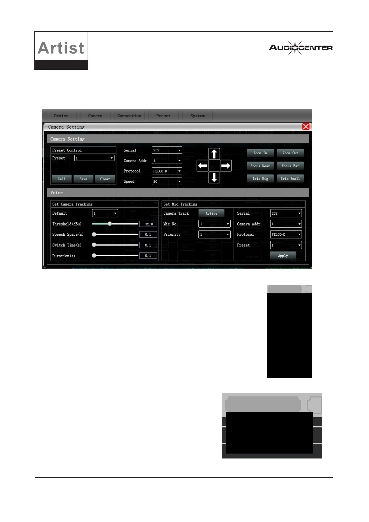
Camera
Connection
Click "Camera" in the menu, and then the camera interface as shown in the right figure will come out, which is used
for camera voice tracking settings.
Please refer to "Camera Settings" on page 23 for detailed camera settings.
1.Port: set connection mode, port number and baud rate.
2.Connect: connect and download the device parameters.
3.Disconnect: disconnect the connected device.
4.Connect ALL: connect and download the parameters of all devices in the device list.
5.Disconnect ALL: disconnect all connected devices in the device list.
6.Port Setting: set the baud rate of the device.
Audio Matrix
Connection
Port
Connect
Disconnect
Connect All
Disconnect All
Port Setting
Preset
Device Preset
Channel Preset
Preset
1.Device Preset: Click the preset management interface to manage the
preset. For details, please refer to "Preset Management" on page 20.
2.Channel Preset: Click the preset management interface for output
channel, and the users can load Audiocenter standard presets or
customized presets for the speakers through this function. For details,
please refer to "Preset Management" on page 20.

System
Language
About
Upgrade
Help File
9
Audio Matrix
System
4.Help File
Scan
Setting
1.Language: multi languages switch.
2.About: for the current firmware and device version information.
3.Upgrade: upgrade the firmware of the device.
Click the "Scan" button to directly scan all devices currently
in connection mode, and display the scanning progress as
shown in the right figure.
Set the connection mode of the scanning device and click the
“Setting” button, and then the right figure will come out.
If the device port changes, click the "Refresh" button to update the
port list instantly.
Connection
COM USB TCP UDP
OK Cancel
Refresh
Port
Boute
COM1
115200 bps
Link
To set the parameters of multiple devices at the same time, click the "Link" button, and the net link interface as shown
in the following figure will come out. Select the devices to be set at the same time on the left, move to the create group
in the middle, and then select the group setting parameters on the right. Finally, press the "OK" button to make the group
function effective. You can also use the same operation to correct the net group settings.

10 Audio Matrix
Device
When the software scans or you add a simulation device, the corresponding device will
be automatically added to the device list, which is convenient for users to interact with
the required devices and operate multiple devices at the same time.
Local IP address
When the software is opened, it will automatically obtain the address of the
network connection corresponding to the network adapter that has been in
effect in the current computer system, which is convenient to manage the IP
address of the device.
Devices List
Scan Setting Link
Device
1.T88D
169.254.184.20 T88D
M.VOL 0.0
2.T88D
3.T88
IP:169.254.184.163;192.168.3.26
In 1 In 2 In 3 In 4 In 5 In 6 In 7 In 8 T4 Out 3 Out 4 Out 5 Out 6 Out 7 Out 8
T3
MICLINE LINE LINE LINE LINE LINE LINE
Master
Volume
MUTE
0.0
0
-100
0.0
MUTE
4
2
3
1
0.0
MUTE
4
2
3
1
0.0
MUTE
4
2
3
1
0.0
MUTE
4
2
3
1
0.0
MUTE
4
2
3
1
0.0
MUTE
4
2
3
1
0.0
MUTE
4
2
3
1
0.0
MUTE
4
2
3
1
0.0
MUTE
4
2
3
1
0.0
MUTE
4
2
3
1
0.0
MUTE
4
2
3
1
0.0
MUTE
4
2
3
1
0.0
MUTE
4
2
3
1
0.0
MUTE
4
2
3
1
0.0
MUTE
4
2
3
1
0.0
MUTE
4
2
3
1
Function module control key
You can click the corresponding module to enter the corresponding operation page.
List of input and output channels
It can display the level, gain, input mode, channel name and other information of each channel, control the main switch of
corresponding channel gain and mute, and turn on the group link function of input and output channels, so as to realize
more powerful and convenient operation.

11
Audio Matrix
INPUT
INPUT
NOISE GATE
NOISE GATE
Threshold
-120.00 dBu
Release
1.00 ms
Attack
1.00 ms
ON
Introduction to function interface
Click in the module button, and the channel input module shown on the right will pop up.
As shown in the figure on the right, the polarity, mute and input mode of the corresponding input
channel can be operated.
Three input modes are optional: analog input, digital input and test signal. One channel can only have
one input mode.
Dante and test signal switch together for every two channels.
A:Analog input is divided into LINE and MIC. MIC input can set 48V phantom power supply (NONE/48V),
sensitivity selection (0 ~ 40dB) and AFC function.
B:T88D supports four Dante network audio inputs (channel1 to 4 ).
C:As shown in the figure below, the channel test signal is set to switch every two channels together, and the test signal
can be "sine wave", "pink noise" and "white noise". If it is selected as an analog signal, it will be switched back to the analog signal input.
Click in the module button to enter the input noise gate to set the module.
As shown in the figure above, click the noise gate switch to turn on or off the function of
the noise gate of the channel. Green means turn on and red means turn off.
Attack time :Enter the corresponding value in the value box to control the Attack time.
Release time:Enter the corresponding value in the value box to control the release time.
Threshold level :Enter the corresponding value in the value box to control the threshold level.
Mute
Analog LINE
MIC
AFC
NONE
Level 1 Level 2
Digital
Test Digital
Setting
0dB
Dante

12 Audio Matrix
PEQ-X
Click in the module button, and then the PEQ setting interface as shown in the following figure will pop up.
The button at the upper right corner of the module can enlarge the module, which can make the interface more clear.
Phase: display the phase curve of the current channel.
View: show or hide all equalization control points.
Bypass: turn on or off all EQ equalizers of the current channel at the same time.
Preset: save the current equalizer setting parameters to the computer, and recall and overwrite the existing equalizer
parameters.
Copy:copy the current equalizer parameter value and paste it into another input channel.
Paste: can be used together with the copy button, And can paste the equalizer parameter values copied by the copy
function to the current channel.
Reset: reset the equalizer parameters to the default values.
EQ curve display of multi channels
As shown in the figure below, EQ curve display switch of each channel is shown on the left. When turn it on, the EQ curve
of the corresponding channel will be displayed in the EQ curve chart.
Input equalizer (PEQ-X)
.
13
Audio Matrix
AUTO MIX
-60
12
PR
0.0
In 1
0.00
Gain
Slope
Response
-60 -60 -60
12 12 12
PR PR PR
0.0 0.0 0.0
In 2 In 3 In 4
0.00 0.00 0.00
-60
12
PR
0.0
In 5
0.00
-60 -60 -60
12 12 12
PR PR PR
0.0 0.0 0.0
In 6 In 7 In 8
0.00 0.00 0.00
1
2
3
4
5
6
7
8
Output
0.00 dB
0.00
0.00
dB
dB
DELAY
DELAY
MIX
In 1
In 2
In 3
In 4
In 5
In 6
In 7
In 8
Bypass 0.00 ms Bypass Out1
Bypass
Bypass
Bypass
Bypass
Bypass
Bypass
Bypass
Bypass
Bypass
Bypass
Bypass
Bypass
Bypass
Bypass
Out2
Out3
Out4
Out5
Out6
Out7
Out8
0.00 ms
0.00 ms
0.00 ms
0.00 ms
0.00 ms
0.00 ms
0.00 ms
0.00 ms
0.00 ms
0.00 ms
0.00 ms
0.00 ms
0.00 ms
0.00 ms
0.00 ms
Bypass ft cm ms Bypass
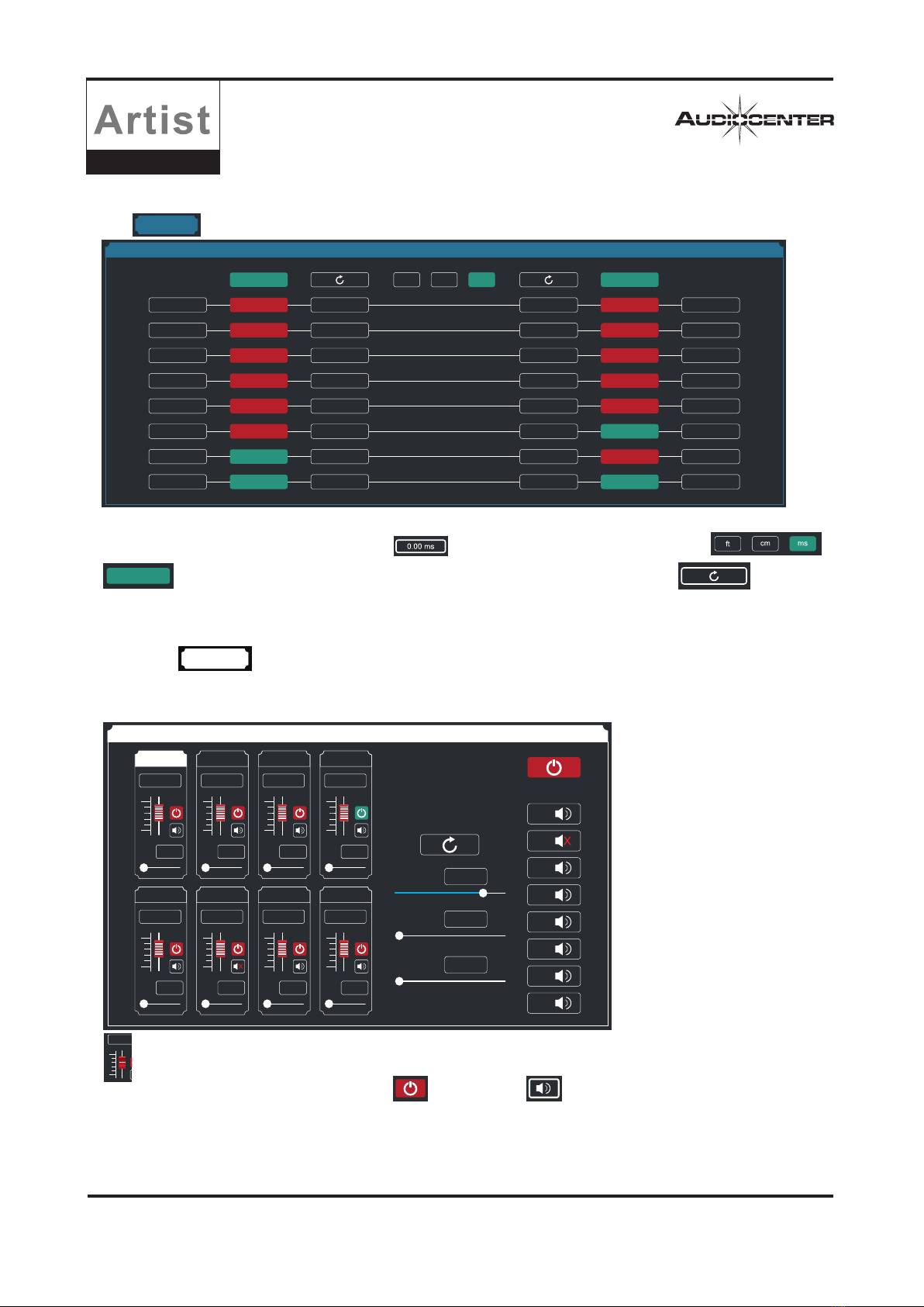
DELAY
AUTO MIX
-60
12
0.0
Click in the module button to enter the I / O delay setting module.
As shown in the figure above, the time delay control contents of all input / output channels are listed.
Input the corresponding number in the value box,and the delay unit can be selected through ;
is the switch of delay function: red means off, green means on; upper reset button can directly reset
the default value of channel delay.
Bypass
Double click in the module button, and then the automatic mixing setting module in the figure below will
pop up, which can control the corresponding relationship (many-to-many relationship) between the input and output
channels when the automatic mixing function takes effect. Input part, as shown in the figure below, the left part is the
automatic mixing setting module of the input part.
is the input mixing gain of the corresponding channel. Drag the slider or input the corresponding value in the
value box at the top; channel input mixing switch and mute switch control whether it is effective (red
means off, green means effective); You can adjust the priority of the channel 0-10 to control PR value. The highest
priority is level 10.
The middle part from top to bottom is all parameters reset button, input mix total gain, mix slope, mix response time.
In the output section, the top right corner is the main output switch. To turn on the mixing function of the output section,
the switch must be turned on (red means off, green means on), and below are the switches of each output channel.

14 Audio Matrix
MATRIX MIX
MATRIX MIX
PEQ-X
Click in the module button, and then the matrix mix setting module as shown below will pop up.
In the figure above, the left is output channel, and the upper is input channel. The value box with the value is the input /
output channel mixing key. When the mixing key is green (double-click the value box to switch the state), signals of input
and output channel realize the mixing function.
The right part of the above figure includes the gain, reset button, and clear button of the matrix mix. Click the value box on
the left, drag the sliding block of matrix mixing gain or input value in the value box to adjust the gain in this matrix block,
Click the reset button to reset the matrix mixing function to the initial one-to-one state, Click the clear button to clear all
matrix mixing functions, and there is no corresponding relationship between the input and output of the device.
Output equalizer (PEQ-X)
Click in the module button, and then theinterface of the output equalizer setting module as shown in the
following figure will pop up. The function and operation mode are the same as those of the input equalizer.

15
Audio Matrix
OUTPUT
LIMITERS
OUTPUT
LIMITERS
Click in the module button, and then the output setting module as shown in the following figure will pop up.
Click in the module button, and then the output setting module as shown in the following figure will come out.
As shown in the figure above, the polarity and mute setting of the corresponding output channel can be controlled.

16
Audio Matrix
Master
Volume
MUTE
0.0
0
-100
Out 3
0.0
MUTE
4
2
3
1
1
In 1
LINE
0.0
MUTE
4
2
3
1
1
Input channel
On the list of input and output channels in the software homepage, the left part is the input channels, as
shown in the figure below.
Channel name
Input level status display
Mute button
Input mode of the current channel
Input volume control
Display and control of input volume
Group link of input channel (when the background
color of corresponding number changes to yellow ,
it means that the channel is in the input group of
corresponding number)
Output channel
On the list of input and output channels in the software homepage, the right part is the output channels,
as shown in the figure below.
Channel name
Output level status display
Mute button
When this channel has Dante, it means that the channel has
Dante output function (There is analog output at the same time)
Output volume control
Display and control of output volume
Group link of output channel (when the background color of
corresponding number changes to yellow ,it means that
the channel is in the output group of corresponding number)
Total volume control
On the list of input and output channels in the software homepage, the middle part is the total volume
control, as shown in the figure below.
Master volume
Total mute button
Display and control of total volume
Total volume control

17
Audio Matrix
<1>
Device
Artist T88D
0 dB
M .VOL
USB
<1> Device 1
USB
<2> Device 2
0 dB
M .VOL
Artist T88
Demo Device
Device 1
Artist T88D
USB
The device list of the software homepage is shown in the
figure on the right
is the number of the device connected
is the device name (user can change the device name in the software)
is the product name (user cannot modify, this example picture shows
Artist T88D)
is the connection mode used by the device (USB, TCP, COM, this example
picture shows USB)
from left to right, shows device lock display, mute control state,
refresh button and remove device button
If you need to debug different devices, you can click to select the target device, and the interface will be updated to the
device function page.
Click "File"→"Demo Device" in the menu bar of the main interface of the software, and then the interface of adding
devices as shown in the figure below will pop up. Select the virtual device model to be added and add it to the device list.
Note: virtual devices cannot connect to real devices.
File Device Camera
Home
T88
T88D
New Project
Demo Device
Open
Save
Save As

18
设备列
Audio Matrix
Devices management
Software Info:display the version number and date of the upper and lower computer of the current device.
Device Info: display the current device name, device group and factory information. To display the factory name, you need
to press the hide shortcut key Ctrl + Alt + F12, where a new name can be input in "Device Name" and "Factory Name", and
then click button to save.
Click " Device "→" Device " in the menu bar of the main interface of the software, and then the interface of device
management as shown in the figure below will pop up.
Device IP information: if the current device is connected with network information, the IP address, gateway and MAC
address of the device will be displayed here. The IP and gateway can enter new information and click the OK button to
save and restart the device network module. The newly entered network information will take effect in time.
Preset management of output channel (Channels)
Click " Device "→" Channel Name" in the menu column of the main interface of the software, The channel name management
will pops up as the following picture shows.
This manual suits for next models
1
Table of contents
Other Audiocenter Stereo System manuals


