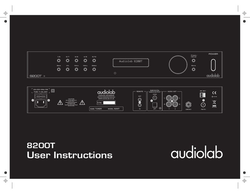
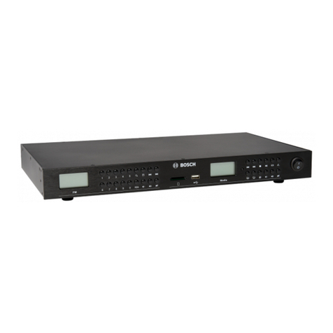
Audiolab 8200T User manual

8200T
Band Info Menu
Mono Store
Select
POWER
Preset
/
Manual
1/62
/75/104/93/8

8200T
VERSION HISTORY
Rev
V01
Date Update Content
2011.06.10 First Version

CONTENT
8200T
Introduction
ia
screen of Bottom
Assembly Parts List
Electronic Parts List
/
Specification
Assembly Sketch
Schematic Diagram
Wir ng Di gram
Silk Top
Maintenance Alignment Procedure
1.
2.
3.
4.
5.
6.
7.
8.
9.
1
2-4
5
6-8
9
10-13
14
15-16
17-22

INTRODUCTION
1
8200T
No part of this document may be reproduced or transmitted in any form or by any means,electronic or
mechanical, for any purpose, without the express written permission of International Audio Group
Limited (IAG)
This manual is for the exclusive use of IAG, its approved distributors and approved UK service agents.
No part of this manual shall be transferred to any other party without the express written permission of
IAG.
It is the responsibility of the user to ensure that all the information contained in this manual is current.
Notification for new issues of this manual and minor updates will be given via the IAG web-site or on
request.
This manual has been prepared with the greatest care, it is intended for information only and no liability
shall be accepted for errors or changes to specification.
For further service information, parts lists and updates, please contact our web-site at
www.international audio group.com .
2011 International Audio Group Limited. All rights reserved.
C

SPECIFICATION
2
8200T
1.FM Section
Frequency Range
CE&UL 87.5-108MHz Step 50KHz
1): Power supply voltage & Frequency (need to same as the product code)
CCCType 220V/50Hz .+/-10%
CEType 230V/50Hz .+/-10%
2): Temperature & Humidity
Temperature 5 ~45
Humidity 50 ~90 % RH
3):a. Set Volume at max
b.take on the EQ model
c. set the bass ,balance filter at no use model
d.take off the EQ model
4):testbyatuotestsystem
°C
Test conditions
Measurement item FREQ Unit Limit Remarks
1 Usable sensitivity MONO IHF(3% THD) 98MHz dBu ≤18
2 S/N RATIO MONO (60dBU IHF A wtd) 98MHz dB ≥72
3 S/N RATIO STEREO (60dBU IHF A wtd) 98MHz dB ≥66
9 Channel Separation (60dBu IHF A wtd) 98MHz dB ≥32
11 FM output Level 98MHz V 1.8 to 2.2
12 Output DC offset 98MHz mV ≤3
98MHz % 0.4
5STEREO THD (60dBu IHF wtd)
L=R,C=40KHz Dev 98MHz % 0.6
4MONO THD (60dBu IHF wtd)
L=R,C=40KHz Dev
6IF Rejection
(10.7MHz) (ref to item1) 98MHz dB
7Image Rejection
(119.4MHz) (refer to item1) 98MHz dB
98MHz dB
≥70
≥40
≤-3
10 Alternate channel selectivity
(+/400KHz,IHF) 98MHz dB ≥60
8Frequency response 20Hz-15KHz (1KHz
Ref, UL=75uS,CE=50uS)
≤3213 RDS decode sensitivity , 4%
DEVIATION 57KHz dBu

2.AM Section
Frequency Range
UL 530-1710KHz Step 10KHz
3.DAB Section
SPECIFICATION
8200T
3
Measurement item FREQ(KHz) Unit Limit Remarks
2 S/N RATIO (5mV input) 999/1000 dB ≥38
3 THD (5mV input) 999/1000 % ≤3
4 Selectivity 999/1000 dB ≥17
+/-36Frequency response
100-2.3KHz(400Hz,5mV) 999/1000 dB
1-1.5
1Usablesensitivity(400Hz,20
dB,direct input)
5 Output (30%,10mV) 999/1000 V
999/1000 dBuV ≤32
Measurement item Measurement condition Unit Limit Remarks
1Frequency
response(42-20KHz)
Play G06P01T1.PLY 42HZ-
20KHZ signal dB -3
2THD(1KHz)
Play G06P01T1.PLY, 1KHZ
signal %0.2
3 Output Level Play G06P01T1.PLY, 1KHZ
signal V 1.4±0.2
5 sensitivity Play G06P01T1.PLY, 1KHZ
signal dB ≥80
Play G06P01T1.PLY,1KHZ
signal(OFF RF) dB ≥65
6 Channel Separation Play G06P01T1.PLY,
1KHZ signal (OFF RF) dB ≥60
4S/N

Functional
SPECIFICATION
8200T
4
Measurement item Measurement condition Unit Limit Remarks
1 Remote control distance 30℃M≥5
2Operating voltage in range
from AC voltage CE AC230V % ±10
3Operating voltage in range
from AC voltage UL AC120V % ±10
4 Operating Temperature ℃0to+45
5 IR output voltage Level V 2.8V to 3.5V
6IR accept input volaget
Range V3to12
7 COAXIAL output Level 75 OHM loading V 0.5 to 1
8 COAXIAL THD 1KHz % ≤0.2

ASSEMBLY SKETCH
5
8200T

SCHEMATIC DIAGRAM
6
8200T
8200T-Mainboard-P1/2

SCHEMATIC DIAGRAM
7
8200T
8200T-Mainboard-P2/2

SCHEMATIC DIAGRAM
8
8200T
8200T Front Board-P1/1
A2
DWG NO: SIZE: REVISOR DATE ISSUE DESCRIPTION OF CHANGE
PCB P/N:
DATE: SHEET: 1/1
DESIGNER:
PRODOUCT NAME:
TITLE:
BRAND:
IAG
IAG Group LTD.
ISSUE:
AUDIOLAB
MAIN SCH
8200T
SZ Lin
2010-9-14
053-1030411048R A00
C003042-S04
SZ Lin
2010-9-14
A00 Release for DC
NC
1VBAT
2PC13-TAMP-RTC
3PC14-OSC32-IN
4PC15-OSC32-OUT
5PD0-OSC-IN
6PD1-OSC-OUT
7RST
8PC0
9PC1
10 PC2
11 PC3
12 VSSA
13 VDDA
14 PA0-WKUP
15 PA1
16 PA2
17 PA3
18 VSS-4
19 VDD-4
20 PA4
21 PA5
22 PA6
23 PA7
24 PC4
25 PC5
26 PB0
27 PB1
28 PB2
29 PB10
30 PB11
31 VSS-1
32 VDD-1
33
PB12
34
PB13
35
PB14
36
PB15
37
PC6
38
PC7
39
PC8
40
PC9
41
PA8
42
PA9
43
PA10
44
PA11
45
PA12
46
PA13
47
VSS-2
48
VDD-2
49
PA14
50
PA15
51
PC10
52
PC11
53
PC12
54
PD2
55
PB3
56
PB4
57
PB5
58
PB6
59
PB7
60
BOOT0
61
PB8
62
PB9
63
VSS-3
64
VDD-3
IC18 STM32F101RBT6
1VSS 2VDD
3V0 4RS
5R/W 6E
7DB0 8DB1
9DB2 10DB3
11 DB4 12DB5
13 DB6 14DB7
15 LED+ 16LED-
LCD1 LCD-0306121
R1441M
C135 22P
C134 22P
Y112M
R135 47K
C68
0.1u
C67
0.1u
R65 NC
Q11MMBT2222 R133 7.5K
R85 4.7K
Q12MMBT2222 R131 1.5K
R86 4.7K
LED1ON
R134 3.3K
1A0
2A1
3A2
4VSS 5SDA
6SCL
7WC
8VCC
IC19 AT24C16
1OUT
2GND
3VCC
IR1
R111
22R
R874.7K
R96 NC
1
GND/ADJ
2VOUT
3VIN
IC8 1117-3.3
C118 10u
C113 220u
C55 0.1u
C114 220u
C58 0.1u
S1 1/6 R98 10K
R121 1.8K
C60 0.1u
S2 2/7
R123 2.49K
S3 3/8
R125 3.9K
S4 4/9
R127 6.8K
S5 5/10
R143 20K
R142 1.8K
L16 60
C56 0.1u
L14 60
C57 0.1u
R132 1K
C62
0.1u
C63
0.1u
C64
0.1u
C65
0.1u
R66 NC
R67 4.7K
R68 4.7K
R69 4.7K
R951K
R74
4.7K
R934.7K
R734.7K
R724.7K
R714.7K
R70
4.7K
C66 0.1u
S7 INFO R99 10K
R122 1.8K
C61 0.1u
S8 ST/MO
R124 2.49K
S9 MENU
R126 3.9K
S10 SEL
R128 6.8K
S11 PRESET
1
2
3
4
5
ENC1 24P24-ENCODER
C145 NC
12
34
56
78
910
11 12
13 14
15 16
17 18
19 20
J8 CN10X2P254
R80 4.7K
R81 0
R82 0
R83 4.7K
R84 4.7K
R79 4.7K
R78 4.7K
R94 0
R77 0
R76 4.7K
R75 4.7K
R136 22R
R105 10K
R104 10K R103 10K
R102 10K
R101 10K
R108 10K
R106 10K
R107 10K
C119 10u
1-
2+
J9
R109 10K
12
34
56
78
910
11 12
13 14
15 16
17 18
19 20
21 22
23 24
25 26
J1B FROM MB
P3
R129 20K
S6 BAND
R130 20K
S12 STORE
R91 4.7K
R92 4.7K
R112 100R
R113 22R
P2
P1
C29 220u
R154 22R
C136
47P
C142 220u
S13
S14
S15
S16
S17
S18
C1
0.1u
C2
0.1u
C3
0.1u
C4
0.1u
C5
0.1u
C6
0.1u
MCU-5V BL-
3V3
3V3
3V3
3V3
3V3
KEY1
KEY2
SCL
SDA
TUN-ST
TUN-DET
RDS-DAVN
DAB-ON
DAB-RST
DAC-RST
DAC-CS
DAC-CCLK
DAC-CDTI
MUTE
BL-
MCU-5V
3V3
SCL
SDA
MCU-5V
3V3
3V3
5VB
MCU-5V
MCU-5V
3V3
3V3
KEY1
VLCD
VLCD
VLCD
3V3
KEY2
QUAD/P PHASE/P
QUAD/P
PHASE/P
AC-OFF
3V3
DB4
DB6
DB5
DB7
DB7
DB6
DB5
DB4
LEDM
LEDL
LEDM
LEDL
TRST
TDO
TDI
TCK
TMS
R/W
RS
E
R/W
RS
E
TRST
TDI
TMS
TCK
TDO
RST
RST
3V3
DAB-ON
DAB-RST
SDA
SCL
TUN-ST
TUN-DET
RDS-DAVN
DAC-RST
DAC-CS
DAC-CCLK
DAC-CDTI
MUTE
IR-LOCAL
AC-OFF
IR-MCU-O
TX
RX
TX
RX
IR-LOCAL
IR-IN
IR-IN
5VB
IR-MCU-O

WIRING DIAGRAM
9
8200T
8200T Wiring Diagram-P1/1
SZ Lin
SZ Lin
C003042-S01
053-1030411000R
SHEET: 1/3
Release for DC
A00
2010-9-14
A00
2010-9-14
8200T
MAIN SCH
AUDIOLAB
ISSUE:
IAG Group LTD.
IAG
BRAND:
TITLE:
PRODOUCT NAME:
DESIGNER:
DATE:
PCB P/N:
DESCRIPTION OF CHANGE
ISSUE
DATE
REVISOR
SIZE:
DWG NO: A2
POWRE TRANFORMER
115V/230V
SELECT
MAIN BOARD
MCU LCD BOARD
LCD
FM/AM MODULE
DAB MODULE
AC SOCKET
5PINS
20PINS
AC11V
GND
AC11V
AC9V
AC9V
SDA
SCL
RDS-DAVN
TUN-DET
TUN-ST
TUN-ON
DAB-RST
DAB-ON
DAC-CDTI
DAC-CCLK
DAC-CS
DAC-RST
MUTE
+9V
5V STBY
STBY-CT
GND
IR1
POWER ON
RDS
DAC
AUDIO AMP
radio buffer and 19K LPF
dac LPF
switch relay
audio output stage
mute relay
9V
+-9V
3.3V
5V
+-9V
5V
5V
5V +-9V
5V 3.3V

10
SILK TOPSCREEN OF BOTTOM
/
8200T-MainBoard Top Silkscreeen-P1/1
8200T

11
8200T
SILK TOPSCREEN OF BOTTOM
/
8200T Voltage Convert Silkscreeen-P1/1

SILK TOPSCREEN OF BOTTOM
/
8200T Front Board Top Silkscreeen-P1/1
12
8200T

SILK TOPSCREEN OF BOTTOM
/
8200T Front Board Bottom Silkscreeen-P1/1
13
8200T

MAINTENANCE ALIGNMENT PROCEDURE
14
8200T
8200T -Ageing test step-P1/1
1):Press the power button on the panel of the unit,then the green LED will be lightened on.Adjust the
frequence shown to be "FM 104.3Mhz". After this the output of the "OUTPUT" terminal on the rear panel
will keep changing.running for 4hours.
2):keep the above testing conditions, check whether everything is normbal while and after the unit
keepsrunning for 4hours.
3.Power off the unit after finishing the test.Do not forget to make a mark or label on the units
which has already been tested,and then place them on the indicated zone for following tests.
1.Device connecting & setting
1):Plug the ageing test special power supply to the power socket on the rear panel of the unit.
2):Plug the Antenna of tuner in the jack of rear panel;
2.Ageing test

ASSEMBLY PARTS LIST
15
8200T
R/N P/N PART NAME DESCRIPTION QTY
1 300-1030410000R Front Panel finish and anodized 1
2 205-1030410001R Button bracket 32*92*4 ABS 1
3 231-3007005102R Rubber washer Φ5*Φ7*1mm 12
4 340-1020410000R Function button painted 12
5 534-3002061006R Screw M3*6 19
6 319-1027410001R Side panel sand blasting ,anodized 2
7 604-1030410001R Main chassis painted and silkscreen 1
8 088-1030414001R Front PCBA PCBA 1
9 588-3000066037R Screw M3*6 14
10 088-1030410000R Main PCBA PCBA 1
11 524-2923090616R Screw ST2.9*9.5 2
12 302-1020410000R Top cover sand blasting ,anodized 1
13 524-2025050601R Screw ST2*5 1
14 534-3002100606R Screw M3*10 13
15 044-1700000000QR AC socket AC socket 1
16 308-1024000000R Bracket 46.5*23.2*10mm T=1.6mm
SECC 1
17 231-1152070054R PC pad 70*152*0.5(Thickness) 1
18 223-0630120601R Plastic post TP-6 4
19 534-3002060021R Plastic screw M3*6 4
20 053-1020410152R POWER PCBA POWER PCBA 1
21 500-6010500300AR Nut M6 1
22 513-6412150780R Washer 6.4*12*1.5 1
23 022-2000042360R Power transformer AUDIO LAB 8200T 1
24 231-2087007100R Transformer Washer Φ68 1
25 263-0020100102R EVA 20*10*10 1
26 588-3000086037R Screw M3*8 4
27 226-1550830331R Feet Φ23*Φ19*13 4
28 226-0230001911R Feet Φ23.7*13.7*19.2 4
29 226-0080031911R Feet Mainstay Φ8.0*Φ3.7*19.0 4
30 305-1030410000R Potentiometer Bracket Painted 1
31 709-0011200020R Mains Swicth Bracket painted 1
32 242-1008010000R Button Bracket 55.3*26.8*4mm 1
33 215-1027410001R Platic Washer painted 1
8200T-Assembly Bom-P1/2

Remark:Colour DifferenceTable
ASSEMBLY PARTS LIST
16
8200T
8200T-Assembly Bom-P2/2
R/N P/N PART NAME DESCRIPTION QTY
34 215-1027410000R Power Button painted 1
35 243-1009410000R Plastic Washer Φ6*Φ9*6.5*18 1
36 574-3002100803AR Knob paited Φ38 1
37 206-1020410000R Display Window Glass 34*93*1.5 PMMA 1
38 111-0100183000R Double-sideTape1 34*93*0.12 1
39 206-2024000001R IR Display Window D12*2.5 1
40 422-0150080102R Double-sideTape2 D15*D8.5*0.12mm 1
41 071-0000000001R Wires Clip FCJ40 1
42 500-3050240300AR Nut M3 6
R/N P/N PART NAME DESCRIPTION QTY
302-1030410000R screened light grey(silver anodized) 1
302-1030420000R screened light grey(black anodized) 1
340-1020410000R silver painted 12
340-1020410001R black painted 12
319-1027410000R silver painted 1
319-1027420000R black painted 1
604-1030410001R silver painted 1
604-1030420000R black painted 1
534-3002061006R M3*6NI 19
534-3002060906R M3*6 BLACK 19
524-2923090616R ST2.9*7.5NI 1
524-2923091016R ST2.9*7.5 BLACK 1
302-1020410000R sand blasting ,anodized silver 1
302-1020410001R sand blasting ,anodized black 1
524-2025050601R M2*5NI 1
524-2023061001R M2*6.5 BLACK 1
534-3002100606R M3*10NI 13
534-3002100906R M3*10 BLACK 13
205-1027410001R silver painted(ABS757#) 1
205-1027420001R black painted(ABS757#) 1
215-1027410000R silver painted(ABS757#) 1
215-1027420000R black painted(ABS757#) 1
340-1030410000-1R silver painted 1
340-1030410001-1R black painted 1
36
14
33
34
Screw
Platic Washer
Power Button
Knob
Top cover12
Screw13
9Screw
Screw11
Side panel6
Main chassis7
Front Panel1
Function button4

ELECTRONIC PARTS LIST
17
8200T
8200T - -P1/6Electronic Bom
R/N P/N PART NAME DESCRIPTION LOCATION QTY
1 044-1700000000QR Power Socket MAINSINLET2POLE2
FUSE LOCS 1
2 055-0326015128R Flat Cable UL2651#28*26P*250MM J1A--J1B 1
3 017-1231000000R Radio Module MT004MS1-6D KSE 1
4 055-0010005255R FFC Cables 10pin L=50mm,PH=1.25 J3 1
5 017-1362000000R DAB Module GyroSignal Gyro-1128 DAB1 1
6 053-1020410152R Power Switch PCB AUDIOLAB8200CD PCB 1
Layer FR4 1.6MM 1
7 060-4180310312R Dual Jacket Wire UL1672 18 AWG Blue
L=310MM 1
8 060-4180310112R Dual Jacket Wire UL1672 18AWG Brown
L=310MM 1
9 742-3501000000R Heat Sinkable Tube Φ35 Black Power
Socket 0
10 742-0151000000R Heat Sinkable Tube φ1.5 Black L=32MM LED PINS 0
11 724-0353800000R PET Knit Sleeve
φ
10.0,Diametre=0.25mm,ROH
S
0
12 742-1001000000R Heat sinkable tube φ10 Black 0
13 071-0000000001R Flat Cable Holder FCJ-40 1
14 041-1376000000QR Mains Switch SWITCH MAINS 2P SDDSA
3289A SW900 1
15 008-1003025005R Capacitor MKT 10NF/250V 10% C900,C901 2
16 031-2200504121HR Fuse Fuse T1A/250V 213 Series
5*20MM LITTELFUSE
Power
Socket 2
17 033-0050011302QR AM Antenna ANTENNA AM LOOP 1
18 812-1472180000R RF Coaxial
Connector HC-004-014 1
19 036-1307015000R Battery 1.5V 7-Size 2
20 846-0010000001R Fuse Cap FUSE-1 (20*11*6MM) 4
21 062-9118000220R Mains Cable PHP-
307 2PIN H03VV-F3G0.75MM2 1
22 022-2000042360R Transformer 115/230V Power=38W
D=85MM H=38MM 1
23 055-0403015111R Terminal Wire 3PIN PH=3.96MM L=150MM
Blue and Brown 1
24 071-3200000000R Tie Wrap Black 200*2.2MM 5
25 088-1030414001R 8200T PCBA 8200T Front PCBA 1
26 056-4120001144R Male Connector 20PIN 2.54MM Verical J8 1
27 271-0260000000R PCB Bracket PCBHoleSize2.5mm,PCB
PH=6mm 2
28 271-0060000000R PCB Bracket LCI-5,White Nylon 66 4
Other manuals for 8200T
1
Table of contents
Other Audiolab Tuner manuals
