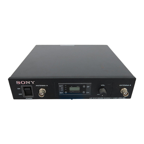
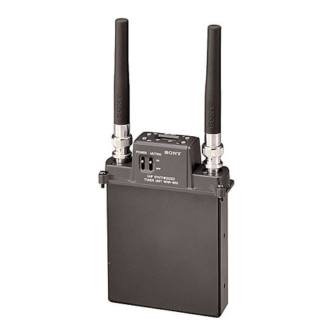
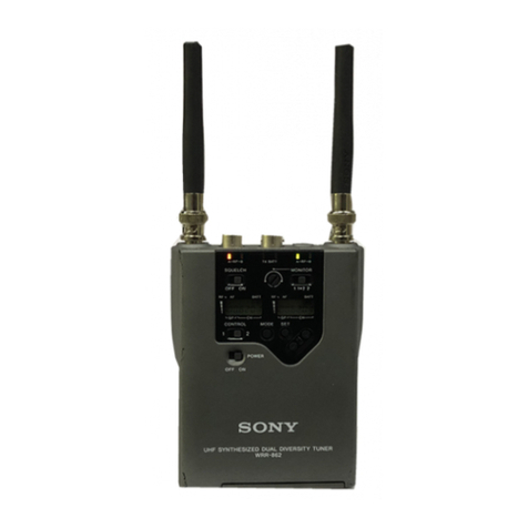
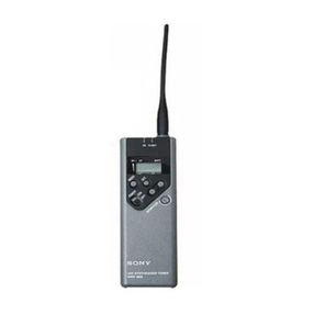
Sony WRR-802A User manual

UHF SYNTHESIZED DIVERSITY TUNER
WRR-802A
SERVICE MANUAL
U Model
1st Edition
Printed in Japan
Sony Corporation 1999. 6 11
Broadcasting & Professional Systems Company ©1999
WRR-802A (U) E
9-976-876-01

!WARNING
This manual is intended for qualified service personnel only.
To reduce the risk of electric shock, fire or injury, do not perform any servicing other than that
contained in the operating instructions unless you are qualified to do so. Refer all servicing to
qualified service personnel.
!WARNUNG
Die Anleitung ist nur für qualifiziertes Fachpersonal bestimmt.
Alle Wartungsarbeiten dürfen nur von qualifiziertem Fachpersonal ausgeführt werden. Um die
Gefahr eines elektrischen Schlages, Feuergefahr und Verletzungen zu vermeiden, sind bei
Wartungsarbeiten strikt die Angaben in der Anleitung zu befolgen. Andere als die angegeben
Wartungsarbeiten dürfen nur von Personen ausgeführt werden, die eine spezielle Befähigung
dazu besitzen.
!AVERTISSEMENT
Ce manual est destiné uniquement aux personnes compétentes en charge de l’entretien. Afin
de réduire les risques de décharge électrique, d’incendie ou de blessure n’effectuer que les
réparations indiquées dans le mode d’emploi à moins d’être qualifié pour en effectuer d’autres.
Pour toute réparation faire appel à une personne compétente uniquement.
WRR-802A (U)

1
WRR-802A (U)
Table of Contents
1. Operating Instructions
2. Service Overview
2-1. Boards Location ..........................................................................................2-1
2-2. Error Messages............................................................................................2-1
2-3. Setting / Release of Muting Function..........................................................2-2
2-4. Service Information for Tuner Unit ............................................................2-2
2-4-1. Tuner Unit Removal...................................................................2-2
2-4-2. Tuner Unit Checking ..................................................................2-3
3. Electrical Alignment
3-1. Preparation ..................................................................................................3-1
3-1-1. Equipment and Tools .................................................................3-1
3-2. Adjustment ..................................................................................................3-2
3-2-1. Tuner Unit Adjustment ..............................................................3-3
3-2-2. Overall Characteristics Check ....................................................3-8
4. Semiconductor Pin Assignments
5. Spare Parts
5-1. Notes on Repair Parts..................................................................................5-1
5-2. Exploded Views ..........................................................................................5-2
5-3. Electrical Parts List .....................................................................................5-4
5-4. Accessories Supplied ................................................................................5-12
6. Block Diagrams
Overall Block Diagram ...............................................................................6-2
Tuner Unit Block Diagram..........................................................................6-3
7. Board Layouts
CN-1922 Board ...........................................................................................7-1
CN-1923 Board ...........................................................................................7-1
MB-872 Board ............................................................................................7-2

2WRR-802A (U)
RE-176 Board..............................................................................................7-2
VR-261 Board .............................................................................................7-2
DP-305 Board (Tuner unit) .........................................................................7-3
RF-92 Board (Tuner unit) ...........................................................................7-3
8. Schematic Diagrams
CN-1922 Board ...........................................................................................8-1
CN-1923 Board ...........................................................................................8-2
MB-872 Board ............................................................................................8-2
RE-176 Board..............................................................................................8-2
VR-261 Board .............................................................................................8-2
DP-305 Board (Tuner unit) .........................................................................8-6
RF-92 Board (Tuner unit) ...........................................................................8-4

1-1
WRR-802A (U)
Section 1
Operating Instructions This section is extracted
from operation manual.
3-867-234-11 (1)
Operating Instructions
Manual de instrucciones
Mode d’emploi
Wireless Channel Lists
Listas de canales inalámbricos
Listes des canaux sans fil
WRR-802A
© 1999 by Sony Corporation
ES
UHF Synthesized
DiversityTuner
US
FR
[U64] [U66] [U68]
2
US
English
Owner’s Record
The model and serial numbers are located at the rear.
Record the serial number in the space provided below.
Refer to them whenever you call upon your Sony dealer
regarding this product.
Model No. WRR-802A Serial No.
WARNING
To prevent fire or shock hazard, do not expose the unit
to rain or moisture.
To avoid electrical shock, do not open the cabinet.
Refer servicing to qualified personnel only.
You are cautioned that any changes or modifications not
expressly approved in this manual could void your authority
to operate this equipment.
Notice for customers in the U.S.A.
Declaration of Conformity
Trade Name : SONY
Model No. : WRR-802A
Responsible Party : Sony Electronics Inc.
Address : 1 Sony Drive, Park Ridge, NJ.07656
USA
Telephone No. : 201-930-6970
This device complies with Part 15 of the FCC Rules.
Operation is subject to the following two conditions: (1) this
device may not cause harmful interference, and (2) this
device must accept any interference received, including
interference that may cause undesired operation.
Notice for customers in Canada:
Use of Sony wireless devices is regulated by the Industry
Canada as described in their Radio Standard Specification
RSS-123. A licence is normally required. The local district
office of Industry Canada should therefore be contacted.
When the operation of the device is within the broadcast
band, the license is issued on no-interference, no-protection
basis with respect to broadcast signals.
Operation of this device is subject to the following two
conditions: (1) this device may not cause interference, and
(2) this device must accept any interference, including
interference that may cause undesired operation of the
device.
1US
Precautions...............................................................1
Overview ...................................................................2
Features ................................................................. 2
System Configuration ........................................... 3
Location of Parts and Controls............................... 4
Front Panel ............................................................ 4
Display .................................................................. 5
Rear Panel ............................................................. 6
Channel Setting ........................................................ 7
Operation ..................................................................9
Muting Functions ................................................ 11
Error Messages ......................................................11
Specifications.........................................................12
Wireless Channel Lists........................................ L-1
Table of Contents Precautions
On operation
• The unit must be used within a temperature range of 0°C to
40°C (32°F to 104°F). Avoid using the unit for extended
periods at extremely high temperatures or placing it in direct
sunlight, especially outdoors because this may damage the
finish of the case. Never install the unit on or near a heat
source, such as lighting equipment or power amplifiers.
• Avoid using in very humid or dusty places, because such
use may shorten the life of the unit.
• To avoid degradation of the signal-to-noise ratio, do not
use the unit in noisy places or in locations subject to
vibration, such as the following:
— near electrical equipment, such as motors, transformers
or dimmers
— near air conditioning equipment or places subject to
direct air flow from an air conditioner
— near public address loudspeakers
— where adjacent equipment might knock against the unit
• Switching lights on or off may produce electrical
interference over the entire frequency range. Position the
unit and the wireless microphones so that interference is
minimized.
• The unit is precisely adjusted at the factory and no
adjustment before use is necessary. Do not touch the
inside of the unit or try to repair it by yourself.
On cleaning
Clean the unit with a dry, soft cloth. Never use thinner,
benzene, alcohol or any other chemicals, since these may
damage the finish.
2
US
Versatile display
A liquid-crystal display provides a variety of information,
including the levels of the reception channels, RF
information and transmitter battery condition.
Space diversity reception system
The WRR-802A provides stable signal reception with
minimum dropout.
Tone squelch circuit for noise elimination
A built-in squelch circuit eliminates noise and signal
interference when the WRR-802A is in signal reception
standby mode.
Compander system
A compander (compressor/expander) system enables
stabilized wireless transmission over a wide dynamic range.
Adjustable audio output level
You can adjust the audio output level by volume.
Overview
The WRR-802A is a reliable UHF synthesized diversity
tuner for the 800-MHz-band Sony UHF wireless
microphone system which uses the frequency bands
allocated for UHF TV broadcasting.
This unit is designed to enable simultaneous use of multiple
channels when channels are selected according to the Sony
channel plan.
For the selectable wireless channels and frequencies, see
“Wireless Channel Lists” on page L-1.
Features
Phase Locked Loop (PLL) synthesized system
The WRR-802A has a refined phase locked loop (PLL)
synthesizer circuit and covers two UHF TV channels. It
operates on 94 channels over a 12-MHz frequency.
Preprogrammed wireless channel plan for
simultaneous multichannel operation
The WRR-802A has many preprogrammed, easily settable
channels in a simultaneous multichannel operation. One
group allows setting of 94 channels. The unit also has 10
preset groups of channels, each of which permits ,
simultaneous operation of 7, 8, 11, 13 or 19 channels
without the effects of intermodulation.

1-2 WRR-802A (U)
3
US
Frequency band Model name
TV channel Transmitter or
microphone
Frequency
(MHz) Tuner
64 770.125 to
775.875 WRT-805A (64)
WRT-807A (64)
WRT-808A (64)
WRT-810A (64)
WRT-820A (64)
WRT-822A (64)
WRT-860A (64)
WRR-802A (64)
WRR-805A (64)
MB-806A with
WRU-806A (64)
WRR-810A (64)
WRR-820A (64)
WRR-840A (64)
WRR-850A (64)
WRR-855A (64)
65 776.125 to
781.875
66 782.125 to
787.875 WRT-805A (66)
WRT-807A (66)
WRT-808A (66)
WRT-810A (66)
WRT-820A (66)
WRT-822A (66)
WRT-860A (66)
WRR-802A (66)
WRR-805A (66)
MB-806A with
WRU-806A (66)
WRR-810A (66)
WRR-820A (66)
WRR-840A (66)
WRR-850A (66)
WRR-855A (66)
67 788.125 to
793.875
68 794.125 to
799.875 WRT-805A (68)
WRT-807A (68)
WRT-808A (68)
WRT-810A (68)
WRT-820A (68)
WRT-822A (68)
WRT-830A (68)
WRT-860A (68)
WRT-867A (68)
WRR-802A (68)
WRR-805A (68)
MB-806A with
WRU-806A (68)
WRR-810A (68)
WRR-820A (68)
WRR-840A (68)
WRR-850A (68)
WRR-855A (68)
WRR-860A (68)
69 800.125 to
805.875
System Configuration
The unit can be used with a Sony UHF synthesized wireless
microphone or UHF synthesized transmitter among the
models listed in the table below.
Sony 800 MHz-band system models
4
US
Front Panel
1POWER switch 2ANTENNA A, B connectors
3GP button
4CH button
5+ button
7Display
1POWER switch
Turns the power on and off.
2ANTENNA A, B (antenna A, B) connectors (BNC
type)
Connect the supplied antennas.
The DC power voltage is not output from the antenna
connector.
3GP (group) button
To change the group, press the + or – button while holding
this button down.
4CH (channel) button
To change the channel in a group, press the + or – button
while holding this button down.
5+ button
To go to a higher group or channel, press this button while
holding the GP or CH button.
Press this button changes the indication from GP/CH to
frequency.
Location of Parts and Controls
ON ANTENNA A VOL. ANTENNA B
OFF
POWER
MIN MAX
CH
GP
+
–
GP CH
BATTAF
RF
6– button
8VOL. Control
5
US
4BATT indication
1AF indicator
2AF level indications
3BATT indicator
1AF (audio frequency) indicator
2AF (audio frequency) level indications
The indicator lights and the indications appear when the
audio output level is higher than the reference level.
3BATT (battery) indicator
4BATT (battery) indication
Indicate the condition of the wireless microphone
transmitter batteries. The indicator and indication appear
and start flashing about one hour before the transmitter
batteries go flat. The time at which flashing begins will
depend on the type of battery used in the transmitter, and its
condition.
5GP/CH (group/channel) indication
Shows the reception channel group and respective channel
number.
Pressing the + button changes this indication to the
frequency indication.
6RF (radio frequency) level indications
7RF (radio frequency) indicator
The indicator lights and the indications (dots) appear when
the antenna reception is optimal. Depending on the RF input
level, the number of dots changes.
6– button
To go to a lower group or channel, press this button while
holding the GP or CH button.
7Display
Displays the status of the tuner and the group and channel
assigned to the unit.
For details, see the following section “Display”.
8VOL. (volume) control
Adjusts the volume of the tuner output.
Display
GP CH
BATTAF
RF
7RF indicator
6RF level indications
5GP/CH indication
6
US
TUNER OUTPUT
LINE LEVEL –20dBm
TRS PHONE BALANCED
LEVEL
LINEMIC
–58dBm –20dBm
DC IN 9V
¥
Rear Panel
1TUNER OUTPUT connector
3TUNER OUTPUT connector
1TUNER OUTPUT (tuner sound output) connector
(XLR type)
Supplies audio signals. You can connect this to the audio
input connector of a mixer, amplifier, or similar equipment.
2OUTPUT LEVEL switch
Select the output level of the XLR-type connector as
–20 dBm or –58 dBm. (0 dBm = 0.775 Vrms)
Set this switch according to the input level of the equipment
connected to the tuner.
2OUTPUT LEVEL switch
Location of Parts and Controls
3TUNER OUTPUT (tuner sound output) connector
(ø6.3 phone balanced (
1
/
4
inch TRS))
Supplies audio signals. You can connect this to the audio
input connector of a mixer, amplifier, or similar equipment.
The output level is fixed at –20 dBm.
4DC IN 9V (9 V DC power input) connector
Connect the supplied AC power adaptor.
5Cord clamp
Attaches the cord of the AC power adaptor.
4DC IN 9V connector
5Cord clamp

1-3
WRR-802A (U)
7
US
Here is explained channel setting for the U68 model as an
example.
Take the following precautions to prevent interference and
noise.
• If there is a TV broadcasting station nearby, to avoid
possible interference from its broadcasting, do not use that
station’s channel.
• When simultaneously using two or more tuners, always set
the tuners to different channels within the same group
(other than group 00).
1
Turn the POWER switch on.
The message “U 68” appears on the display, and then
the current status of this unit is displayed.
Note
Turn the POWER switch on after reducing the volume
of equipment connected to the TUNER OUTPUT
connector. Otherwise, noise will be heard when the
power is turned on.
2
While holding down the GP button, press the + or –
button to select a group.
Each time you press the + or – button, the GP indication
changes as shown in the following figure. To change the
indication continuously, press and hold down the + or –
button.
Channel Setting
GP CH GP CH
+
–
1 3,4 2 2,3,4
(Continued)
8
US
The CH indication shows the lowest frequency channel
of the selected group. For group 00, however, the
channel selected last is displayed.
Releasing the buttons automatically cancels the group
selection mode, and the currently displayed group is
selected.
3
While holding down the CH button, press the + or –
button to select a channel.
Similar to step 2, each time you press the + or – button,
the CH indication changes in the order shown in the
group and reception channel list. (See “Wireless
Channel Lists” on page L-1.)
If you press the + button when the last channel of the
selected group is displayed, the first channel of the
group will be displayed.
Selecting the reception channel by frequency
Press the + button.
This changes the GP/CH indication to a frequency
indication.
To change a frequency, press the + or – button while
keeping the CH button pressed. (A higher or lower
frequency will be displayed.)
Press the + button again to change the frequency
indication back to a GP/CH indication.
4
If the desired channel or frequency is displayed, release
the CH button and + or – button.
The selected channel is set.
To store the selected group and channel
Leave the indication unchanged for 1 second.
The group and channel set in the procedure explained above
are stored in memory.
Channel Setting
GP CH GP CH
+
–
GP CH GP CH
+
–
9
US
1
Connect the supplied antennas and make the antenna
tips point upward.
2
Connect the supplied AC power adaptor to the DC IN
9V connector and an audio mixer or amplifier to the
TUNER OUTPUT connector.
ANTENNA A, B
Audio mixer, amplifier
AC power adaptor
UHF synthesized
transmitter
UHF
synthesized
wireless
microphone
DC IN 9V
TUNER OUTPUT
5
34
1
2
+
–
Operation
3
Turn the POWER switch on.
Note
Turn the POWER switch on after reducing the volume
of the equipment connected to the TUNER OUTPUT
connector. Otherwise, noise will be heard when the
POWER switch is turned on.
4
Set the reception channel.
For details on setting the channels, see page 7.
5
Turn on the wireless microphone or transmitter.
Use the wireless microphone or transmitter to which the
same channel is assigned as to this unit.
If noise is heard
Depending on the environment where the system is
installed, outside noise or radio wave may disrupt the
transmission of certain channels.
To select a channel under this circumstance, turn off the
wireless microphone or transmitter. Then select a channel at
which the RF indicator is off. (A channel free from noise or
radio wave interference is selected.) Set the same channel on
the microphone or transmitter.
10
US
1) The distance depends on the operating environment and conditions.
WRR-802A
AN-820A
WD-820A
Tuner
a) Coaxial cable (30 m (100 feet))
a) a)
Notes on using with a WD-820A
• This unit does not supply the internal booster of the
optional AN-820A UHF Antenna through the ANTENNA
A,B connectors. It is impossible to connect the AN-820A
directly.
• When adding the WRR-802A by cascade connection to a
tuner system containing the WD-820A UHF Antenna
Divider, use a coaxial cable (5D-2V, RG-212/U or
equivalent) with length of 30 m (100 feet) as shown in the
figure.
• To avoid noise, remove the transmitter from the antennas
as far as possible when setting the channel or waiting with
the transmitter powered.
Notes
• Do not simultaneously use two or more microphones and
transmitters that are set to the same channel.
• Separate the reception antennas and the transmitter by
more than 3 m (9 feet 11 inches).
• The number of wireless microphone channels actually
usable in a multi-channel system may be smaller than the
normal capacity of that system if there is interference from
TV broadcasting or other RF signals.
• When operating two or more UHF wireless microphone
systems using the same wireless channel in the same
group, ensure that the systems are at least 100 m (330
feet)
1)
apart as far as they are installed within sight of each
other.
Operation

1-4 WRR-802A (U)
11
US
Apart from the normal indications, the following error
messages may appear on the display.
Meaning Remedy
Err 01
Message
An error has occurred in
the backup memory data. The memory data is
initialized. Reset the
group and channel
settings.
Contact your nearest
Sony dealer.
The PLL-synthesized
circuit has a malfunction.
Err 02
NO TONE As no tone signal is
available or a tone signal
other than 32.768 kHz is
being received, the audio
signal output is muted.
Make sure that the
transmitter is turned on.
If it is, then the problem
lies in the transmitter’s
tone signal generator or
the tuner’s tone squelch
circuit. Contact your
nearest Sony dealer.
If you are using a WRT-
810A wireless
microphone, a “NO
TONE” message
appears when you turn
off the AF switch, but
this is normal.
Error Messages
Muting Functions
This unit has the following three muting functions, which work
in combination.
(1) Muting by RF input level
As sufficient S/N for the audio output may not be obtained if no
RF signal is received or the RF input level is low, the audio
output can be muted when the RF input level falls below the
muting level.
(2) Tone squelch
The audio output is obtained only when the unit receives an RF
signal which includes a specified tone signal. The audio output
is muted to eliminate noise which may be heard when the
transmitter is turned on/off or the unit receives an interference
RF signal.
(3) Noise squelch
The audio output is muted to eliminate noise which may be
heard when there is such excessive interference RF signal that
the tone squelch does not work.
To turn off the muting functions
While holding down the GP and CH buttons, turn the POWER
switch to ON. All indications momentarily appear, then go off.
“OFF” is then displayed. This procedure cancels all three
muting functions at the same time.
To turn on the muting functions
Turn the POWER switch to OFF, then to ON again. The three
muting functions are activated at the same time.
12
US
Tuner
Reception type 110KF3E
Circuit system Dual conversion superheterodyne
Reception frequencies
U64 model: 770.125 to 781.875 MHz
U66 model: 782.125 to 793.875 MHz
U68 model: 794.125 to 805.875 MHz
Local oscillatorsCrystal controlled PLL synthesizer
Selectivity 60 dB or more (at ±250 kHz detuned)
Spurious rejection ratio
70 dB or more
Image rejection ratio
60 dB or more
Muting level 30 dBµ
1)
Antenna connectors
BNC-R type (2), 50 ohms
Frequency response
100 to 15,000 Hz ±3 dB
De-emphasis 50µsec
Signal-to-noise ratio
40 dB or more at an A-weighted RF input
level of 20 dBµ
60 dB or more at an A-weighted RF input
level of 60 dBµ
(±5 kHz deviation at 1 kHz modulation)
Distortion 1% or less (±40 kHz deviation at 1 kHz
modulation)
Tone signal frequency
32.768 kHz
Specifications
Output level –20 dBm
2)
or –58 dBm (±5 kHz deviation at
1 kHz modulation)
Output impedance
150 ohms
Output connector
ø6.3 phone balanced (
1
/
4
inch TRS)
XLR-3-12C
1) 0 dBµ=1 µV
2) 0 dBm=0.775 Vrms (600 ohms loaded)
General
Power requirements
9 V DC
Current consumption
Approx. 600 mA
Operating temperature
0°C to 40°C (32°F to 104°F)
Storage temperature
–20°C to +55°C (–4°F to +131°F)
Dimensions 218 ×44 ×210 mm
(8
5
/
8
×1
3
/
4
×8
3
/
8
inches) (w/h/d)
Mass Approx. 1.6 kg (3 lb 8 oz)
Accessories supplied
AC power adaptor (1)
Antennas (2)
Operating Instructions (1)
Design and specifications are subject to change without
notice.
L-1
Guidance on use of multi-channel system
This product is designed to give excellent interference free
operation in multi-channel systems. To maintain this, Sony
recommends that one of the original Sony groups, number
00, 11, 12, 13, A1, A2, A3, L1, L2, H1 or H2 is selected.
These groups will offer excellent performance, free from
mutual interference from other Sony wireless microphone
transmitters in the selected group when used under the
recommended operating conditions. The remaining groups
are included for compliance with frequency regulations in
various countries, and will not always guarantee interference
free operation.
Group 00 is used to scan for open channels, or to use only
for a one channel system.
Directrices para el uso de sistemas multicanal
Este producto se ha diseñado para proporcionar una
operación excelente sin interferencias en sistemas de
múltiples canales. Para esto, Sony recomienda seleccionar
uno de los grupos originales de Sony, es decir, los número
00, 11, 12, 13, A1, A2, A3, L1, L2, H1 o H2.
Estos grupos ofrecen un funcionamiento excelente, sin
interferencias en ambos sentidos con otros transmisores de
micrófono inalámbrico de Sony del grupo seleccionado,
siempre que se utilicen en las condiciones de
funcionamiento recomendadas. Los demás grupos se han
incluido por motivos de compatibilidad con las normas
sobre frecuencias de varios países y no siempre garantizarán
un funcionamiento sin interferencias.
El grupo 00 sirve para buscar canales abiertos o se utiliza
solamente para sistemas de un solo canal.
Guide d’utilisation du système multicanal
Ce produit est conçu pour assurer un excellent
fonctionnement exempt d’interférences dans les systèmes
multicanaux. A cette fin, Sony recommande de sélectionner
l’un des groupes Sony originaux portant les numéros 00, 11,
12, 13, A1, A2, A3, L1, L2, H1 et H2.
Ces groupes offrent d’excellentes performances, exemptes
d’interférences mutuelles avec d’autres emetteurs de
microphone sans fil Sony dans le groupe sélectionné s’ils
sont exploités dans les conditions d’utilisation préconisées.
Les autres groupes sont inclus pour satisfaire aux
réglementations sur les fréquences dans les différents pays
et ne garantissent pas toujours un fonctionnement exempt
d’interférences.
C’est le groupe 00 qui est utlilisé pour explorer les canaux
ouverts, ou en vue de l’utilisation d’un système à canal
unique.
Wireless Channel Lists/Listas de canales inalámbricos/
Listes des canaux sans fil
L-2
Wireless Channel Lists/Listas de canales inalámbricos/Listes des canaux sans fil
For 68-Version Model Using TV Channels 68 and 69/Para modelos de la versión 68 que utilizan
los canales de TV 68 y 69/Pour le modèle 68 utilisant les canaux de télévision 68 et 69
Group 00: All channel access
Use to scan for open channels. Groupe 00: Accès tous canaux
Pour l’exploration des canaux ouverts.
Grupo 00: Acceso a todos los canales
Se utiliza para buscar canales abiertos.
Channel
Canal Frequency (MHz)
Frequencia
Fréquence
Channel
Canal Frequency (MHz)
Frequencia
Fréquence
Channel
Canal Frequency (MHz)
Frequencia
Fréquence
Channel
Canal Frequency (MHz)
Frequencia
Fréquence
TV-68 Band/Banda de TV 68/Bande télé 68 TV-69 Band/Banda de TV 69/Bande télé 69
68-01 794.125 68-25 797.125
68-02 794.250 68-26 797.250
68-03 794.375 68-27 797.375
68-04 794.500 68-28 797.500
68-05 794.625 68-29 797.625
68-06 794.750 68-30 797.750
68-07 794.875 68-31 797.875
68-08 795.000 68-32 798.000
68-09 795.125 68-33 798.125
68-10 795.250 68-34 798.250
68-11 795.375 68-35 798.375
68-12 795.500 68-36 798.500
68-13 795.625 68-37 798.625
68-14 795.750 68-38 798.750
68-15 795.875 68-39 798.875
68-16 796.000 68-40 799.000
68-17 796.125 68-41 799.125
68-18 796.250 68-42 799.250
68-19 796.375 68-43 799.375
68-20 796.500 68-44 799.500
68-21 796.625 68-45 799.625
68-22 796.750 68-46 799.750
68-23 796.875 68-47 799.875
68-24 797.000
69-01 800.125 69-25 803.125
69-02 800.250 69-26 803.250
69-03 800.375 69-27 803.375
69-04 800.500 69-28 803.500
69-05 800.625 69-29 803.625
69-06 800.750 69-30 803.750
69-07 800.875 69-31 803.875
69-08 801.000 69-32 804.000
69-09 801.125 69-33 804.125
69-10 801.250 69-34 804.250
69-11 801.375 69-35 804.375
69-12 801.500 69-36 804.500
69-13 801.625 69-37 804.625
69-14 801.750 69-38 804.750
69-15 801.875 69-39 804.875
69-16 802.000 69-40 805.000
69-17 802.125 69-41 805.125
69-18 802.250 69-42 805.250
69-19 802.375 69-43 805.375
69-20 802.500 69-44 805.500
69-21 802.625 69-45 805.625
69-22 802.750 69-46 805.750
69-23 802.875 69-47 805.875
69-24 803.000
1-5
WRR-802A (U)
L-3
Group 11: 11-channel group
Use when both TV channels 68 and 69
are open.
Grupo 11: Grupo de 11 canales
Se utiliza cuando los canales de TV 68
y 69 están abiertos.
Groupe 11: Groupe de 11 canaux
Lorsque les canaux de télévision 68 et
69 sont ouverts.
Group 12: 8-channel group
Use when TV channel 69 is open.
Grupo 12: Grupo de 8 canales
Se utiliza cuando el canal de TV 69
está abierto.
Groupe 12: Groupe de 8 canaux
Lorsque le canal de télévision 69 est
ouvert.
Group 13: 8-channel group
Use when TV channel 68 is open.
Grupo 13: Grupo de 8 canales
Se utiliza cuando el canal de TV 68
está abierto.
Groupe 13: Groupe de 8 canaux
Lorsque le canal de télévision 68 est
ouvert.
Channel
Canal Frequency (MHz)
Fréquence
Frequencia
68-05 794.625
68-14 795.750
68-25 797.125
68-41 799.125
68-47 799.875
69-12 801.500
69-16 802.000
69-30 803.750
69-37 804.625
69-40 805.000
69-42 805.250
Channel
Canal Frequency (MHz)
Fréquence
Frequencia
69-01 800.125
69-05 800.625
69-11 801.375
69-25 803.125
69-28 803.500
69-36 804.500
69-41 805.125
69-43 805.375
Channel
Canal Frequency (MHz)
Fréquence
Frequencia
68-03 794.375
68-13 795.625
68-18 796.250
68-26 797.250
68-37 798.625
68-40 799.000
68-44 799.500
68-46 799.750
L-4
Wireless Channel Lists/Listas de canales inalámbricos/Listes des canaux sans fil
Group A1: 19-channel group
The channels listed as Group A1 for
the 64- and 66-version models can be
simultaneously used in combination.
See “Group A1” on pages 8 and 12.
Grupo A1: Grupo de 19 canales
Los canales enumerados en el Grupo
A1 para modelos de las versiones 64 y
66 pueden utilizarse simultáneamente
de forma combinada.
Consulte “Grupo A1” en las páginas
8 y 12.
Groupe A1: Groupe de 19 canaux
Les canaux spécifiés pour le Groupe
A1 pour les modèles 64 et 66 peuvent
être utilisés simultanément en
combinaison.
Voir “Groupe A1” aux pages 8 et 12.
Channel
Canal Frequency (MHz)
Frequencia
Fréquence
68-06 794.750
68-20 796.500
68-24 797.000
68-40 799.000
69-04 800.500
69-17 802.125
69-23 802.875
69-47 805.875
Group A3: 13-channel group
The channels listed as Group A3 for
the 64- and 66-version models can be
simultaneously used in combination.
See “Group A3” on pages 8 and 12.
Grupo A3: Grupo de 13 canales
Los canales enumerados en el Grupo
A3 para modelos de las versiones 64 y
66 pueden utilizarse simultáneamente
de forma combinada.
Consulte “Grupo A3” en las páginas
8 y 12.
Groupe A3: Groupe de 13 canaux
Les canaux spécifiés pour le Groupe
A3 pour les modèles 64 et 66 peuvent
être utilisés simultanément en
combinaison.
Voir “Groupe A3” aux pages 8 et 12.
Channel
Canal
68-10 795.250
68-21 796.625
68-29 797.625
68-35 798.375
68-39 798.875
68-42 799.250
68-44 799.500
Group A2: 13-channel group
The channels listed as Group A2 for
the 64- and 66-version models can be
simultaneously used in combination.
See “Group A2” on pages 8 and 12.
Grupo A2: Grupo de 13 canales
Los canales enumerados en el Grupo
A2 para modelos de las versiones 64 y
66 pueden utilizarse simultáneamente
de forma combinada.
Consulte “Grupo A2” en las páginas
8 y 12.
Groupe A2: Groupe de 13 canaux
Les canaux spécifiés pour le Groupe
A2 pour les modèles 64 et 66 peuvent
être utilisés simultanément en
combinaison.
Voir “Groupe A2” aux pages 8 et 12.
Channel
Canal Frequency (MHz)
Frequencia
Fréquence
69-11 801.375
69-22 802.750
69-30 803.750
69-36 804.500
69-40 805.000
69-43 805.375
69-45 805.625
Frequency (MHz)
Frequencia
Fréquence
L-5
Group L1: 7-channel group
Use when TV channel 68 is
open.
Grupo L1: Grupo de 7
canales
Se utiliza cuando el canal de
TV 68 está abierto.
Groupe L1: Groupe de 7
canaux
Lorsque le canal de télévision
68 est ouvert.
Group L2: 7-channel group
Use when TV channel 68 is
open.
Grupo L2: Grupo de 7
canales
Se utiliza cuando el canal de
TV 68 está abierto.
Groupe L2: Groupe de 7
canaux
Lorsque le canal de télévision
68 est ouvert.
Group H1: 7-channel group
Use when TV channel 69 is
open.
Grupo H1: Grupo de 7
canales
Se utiliza cuando el canal de
TV 69 está abierto.
Groupe H1: Groupe de 7
canaux
Lorsque le canal de télévision
69 est ouvert.
Group H2: 7-channel group
Use when TV channel 69 is
open.
Grupo H2: Grupo de 7
canales
Se utiliza cuando el canal de
TV 69 está abierto.
Groupe H2: Groupe de 7
canaux
Lorsque le canal de télévision
69 est ouvert.
Channel
Canal Frequency
Frequencia
Fréquence
(MHz)
68-09 795.125
68-11 795.375
68-19 796.375
68-25 797.125
68-30 797.750
68-34 798.250
68-37 798.625
Channel
Canal Frequency
Frequencia
Fréquence
(MHz)
68-10 795.250
68-13 795.625
68-17 796.125
68-22 796.750
68-28 797.500
68-36 798.500
68-38 798.750
Channel
Canal Frequency
Frequencia
Fréquence
(MHz)
69-09 801.125
69-11 801.375
69-19 802.375
69-25 803.125
69-30 803.750
69-34 804.250
69-37 804.625
Channel
Canal Frequency
Frequencia
Fréquence
(MHz)
69-10 801.250
69-13 801.625
69-17 802.125
69-22 802.750
69-28 803.500
69-36 804.500
69-38 804.750
L-6
Wireless Channel Lists/Listas de canales inalámbricos/Listes des canaux sans fil
Group 00: All channel access
Use to scan for open channels. Groupe 00: Accès tous canaux
Pour l’exploration des canaux ouverts.
For 66-Version Model Using TV Channels 66 and 67/Para modelos de la versión 66 que utilizan
los canales de TV 66 y 67/Pour le modèle 66 utilisant les canaux de télévision 66 et 67
Grupo 00: Acceso a todos los canales
Se utiliza para buscar canales abiertos.
Channel
Canal Frequency (MHz)
Frequencia
Fréquence
Channel
Canal Frequency (MHz)
Frequencia
Fréquence
Channel
Canal Frequency (MHz)
Frequencia
Fréquence
Channel
Canal Frequency (MHz)
Frequencia
Fréquence
TV-66 Band/Banda de TV 66/Bande télé 66 TV-67 Band/Banda de TV 67/Bande télé 67
66-01 782.125 66-25 785.125
66-02 782.250 66-26 785.250
66-03 782.375 66-27 785.375
66-04 782.500 66-28 785.500
66-05 782.625 66-29 785.625
66-06 782.750 66-30 785.750
66-07 782.875 66-31 785.875
66-08 783.000 66-32 786.000
66-09 783.125 66-33 786.125
66-10 783.250 66-34 786.250
66-11 783.375 66-35 786.375
66-12 783.500 66-36 786.500
66-13 783.625 66-37 786.625
66-14 783.750 66-38 786.750
66-15 783.875 66-39 786.875
66-16 784.000 66-40 787.000
66-17 784.125 66-41 787.125
66-18 784.250 66-42 787.250
66-19 784.375 66-43 787.375
66-20 784.500 66-44 787.500
66-21 784.625 66-45 787.625
66-22 784.750 66-46 787.750
66-23 784.875 66-47 787.875
66-24 785.000
67-01 788.125 67-25 791.125
67-02 788.250 67-26 791.250
67-03 788.375 67-27 791.375
67-04 788.500 67-28 791.500
67-05 788.625 67-29 791.625
67-06 788.750 67-30 791.750
67-07 788.875 67-31 791.875
67-08 789.000 67-32 792.000
67-09 789.125 67-33 792.125
67-10 789.250 67-34 792.250
67-11 789.375 67-35 792.375
67-12 789.500 67-36 792.500
67-13 789.625 67-37 792.625
67-14 789.750 67-38 792.750
67-15 789.875 67-39 792.875
67-16 790.000 67-40 793.000
67-17 790.125 67-41 793.125
67-18 790.250 67-42 793.250
67-19 790.375 67-43 793.375
67-20 790.500 67-44 793.500
67-21 790.625 67-45 793.625
67-22 790.750 67-46 793.750
67-23 790.875 67-47 793.875
67-24 791.000

1-6 WRR-802A (U)
L-7
Channel
Canal Frequency (MHz)
Frequencia
Fréquence
66-05 782.625
66-14 783.750
66-25 785.125
66-41 787.125
66-47 787.875
67-12 789.500
67-16 790.000
67-30 791.750
67-37 792.625
67-40 793.000
67-42 793.250
Channel
Canal Frequency (MHz)
Frequencia
Fréquence
67-01 788.125
67-05 788.625
67-11 789.375
67-25 791.125
67-28 791.500
67-36 792.500
67-41 793.125
67-43 793.375
Channel
Canal Frequency (MHz)
Frequencia
Fréquence
66-03 782.375
66-13 783.625
66-18 784.250
66-26 785.250
66-37 786.625
66-40 787.000
66-44 787.500
66-46 787.750
Group 11: 11-channel group
Use when both TV channels 66 and 67
are open.
Grupo 11: Grupo de 11 canales
Se utiliza cuando los canales de TV 66
y 67 están abiertos.
Groupe 11: Groupe de 11 canaux
Lorsque les canaux de télévision 66 et
67 sont ouverts.
Group 12: 8-channel gruop
Use when TV channel 67 is open.
Grupo 12: Grupo de 8 canales
Se utiliza cuando el canal de TV 67
está abierto.
Groupe 12: Groupe de 8 canaux
Lorsque le canal de télévision 67 est
ouvert.
Group 13: 8-channel group
Use when TV channel 66 is open.
Grupo 13: Grupo de 8 canales
Se utiliza cuando el canal de TV 66
está abierto.
Groupe 13: Groupe de 8 canaux
Lorsque le canal de télévision 66 est
ouvert.
L-8
Wireless Channel Lists/Listas de canales inalámbricos/Listes des canaux sans fil
Group A1: 19-channel group
The channels listed as Group A1 for
the 64- and 68-version models can be
simultaneously used in combination.
See “Group A1” on pages 4 and 12.
Grupo A1: Grupo de 19 canales
Los canales enumerados en el Grupo
A1 para modelos de las versiones 64 y
68 pueden utilizarse simultáneamente
de forma combinada.
Consulte “Grupo A1” en las páginas
4 y 12.
Groupe A1: Groupe de 19 canaux
Les canaux spécifiés pour le Groupe
A1 pour les modèles 64 et 68 peuvent
être utilisés simultanément en
combinaison.
Voir “Groupe A1” aux pages 4 et 12.
Channel
Canal Frequency (MHz)
Frequencia
Fréquence
66-02 782.250
66-24 785.000
66-29 785.625
67-16 790.000
67-18 790.250
67-39 792.875
Group A2: 13-channel group
The channels listed as Group A2 for
the 64- and 68-version models can be
simultaneously used in combination.
See “Group A2” on pages 4 and 12.
Grupo A2: Grupo de 13 canales
Los canales enumerados en el Grupo
A2 para modelos de las versiones 64 y
68 pueden utilizarse simultáneamente
de forma combinada.
Consulte “Grupo A2” en las páginas
4 y 12.
Groupe A2: Groupe de 13 canaux
Les canaux spécifiés pour le Groupe
A2 pour les modèles 64 et 68 peuvent
être utilisés simultanément en
combinaison.
Voir “Groupe A2” aux pages 4 et 12.
Channel
Canal Frequency (MHz)
Frequencia
Fréquence
67-07 788.875
67-33 792.125
67-45 793.625
Group A3: 13-channel group
The channels listed as Group A3 for
the 64- and 68-version models can be
simultaneously used in combination.
See “Group A3” on pages 4 and 12.
Grupo A3: Grupo de 13 canales
Los canales enumerados en el Grupo
A3 para modelos de las versiones 64 y
68 pueden utilizarse simultáneamente
de forma combinada.
Consulte “Grupo A3” en las páginas
4 y 12.
Groupe A3: Groupe de 13 canaux
Les canaux spécifiés pour le Groupe
A3 pour les modèles 64 et 68 peuvent
être utilisés simultanément en
combinaison.
Voir “Groupe A3” aux pages 4 et 12.
Channel
Canal Frequency (MHz)
Frequencia
Fréquence
66-06 782.750
66-32 786.000
66-44 787.500
L-9
Group L1: 7-channel group
Use when TV channel 66 is
open.
Grupo L1: Grupo de 7
canales
Se utiliza cuando el canal de
TV 66 está abierto.
Groupe L1: Groupe de 7
canaux
Lorsque le canal de télévision
66 est ouvert.
Group L2: 7-channel group
Use when TV channel 66 is
open.
Grupo L2: Grupo de 7
canales
Se utiliza cuando el canal de
TV 66 está abierto.
Groupe L2: Groupe de 7
canaux
Lorsque le canal de télévision
66 est ouvert.
Group H1: 7-channel group
Use when TV channel 67 is
open.
Grupo H1: Grupo de 7
canales
Se utiliza cuando el canal de
TV 67 está abierto.
Groupe H1: Groupe de 7
canaux
Lorsque le canal de télévision
67 est ouvert.
Group H2: 7-channel group
Use when TV channel 67 is
open.
Grupo H2: Grupo de 7
canales
Se utiliza cuando el canal de
TV 67 está abierto.
Groupe H2: Groupe de 7
canaux
Lorsque le canal de télévision
67 est ouvert.
Channel
Canal Frequency
Frequencia
Fréquence
(MHz)
66-09 783.125
66-11 783.375
66-19 784.375
66-25 785.125
66-30 785.750
66-34 786.250
66-37 786.625
Channel
Canal Frequency
Frequencia
Fréquence
(MHz)
66-10 783.250
66-13 783.625
66-17 784.125
66-22 784.750
66-28 785.500
66-36 786.500
66-38 786.750
Channel
Canal Frequency
Frequencia
Fréquence
(MHz)
67-09 789.125
67-11 789.375
67-19 790.375
67-25 791.125
67-30 791.750
67-34 792.250
67-37 792.625
Channel
Canal Frequency
Frequencia
Fréquence
(MHz)
67-10 789.250
67-13 789.625
67-17 790.125
67-22 790.750
67-28 791.500
67-36 792.500
67-38 792.750
L-10
Wireless Channel Lists/Listas de canales inalámbricos/Listes des canaux sans fil
For 64-Version Model Using TV Channels 64 and 65/Para modelos de la versión 64 que utilizan
los canales de TV 64 y 65/Pour le modèle 64 utilisant les canaux de télévision 64 et 65
Channel
Canal Frequency (MHz)
Frequencia
Fréquence
Channel
Canal Frequency (MHz)
Frequencia
Fréquence
64-01 770.125 64-25 773.125
64-02 770.250 64-26 773.250
64-03 770.375 64-27 773.375
64-04 770.500 64-28 773.500
64-05 770.625 64-29 773.625
64-06 770.750 64-30 773.750
64-07 770.875 64-31 773.875
64-08 771.000 64-32 774.000
64-09 771.125 64-33 774.125
64-10 771.250 64-34 774.250
64-11 771.375 64-35 774.375
64-12 771.500 64-36 774.500
64-13 771.625 64-37 774.625
64-14 771.750 64-38 774.750
64-15 771.875 64-39 774.875
64-16 772.000 64-40 775.000
64-17 772.125 64-41 775.125
64-18 772.250 64-42 775.250
64-19 772.375 64-43 775.375
64-20 772.500 64-44 775.500
64-21 772.625 64-45 775.625
64-22 772.750 64-46 775.750
64-23 772.875 64-47 775.875
64-24 773.000
65-01 776.125 65-25 779.125
65-02 776.250 65-26 779.250
65-03 776.375 65-27 779.375
65-04 776.500 65-28 779.500
65-05 776.625 65-29 779.625
65-06 776.750 65-30 779.750
65-07 776.875 65-31 779.875
65-08 777.000 65-32 780.000
65-09 777.125 65-33 780.125
65-10 777.250 65-34 780.250
65-11 777.375 65-35 780.375
65-12 777.500 65-36 780.500
65-13 777.625 65-37 780.625
65-14 777.750 65-38 780.750
65-15 777.875 65-39 780.875
65-16 778.000 65-40 781.000
65-17 778.125 65-41 781.125
65-18 778.250 65-42 781.250
65-19 778.375 65-43 781.375
65-20 778.500 65-44 781.500
65-21 778.625 65-45 781.625
65-22 778.750 65-46 781.750
65-23 778.875 65-47 781.875
65-24 779.000
Channel
Canal Frequency (MHz)
Frequencia
Fréquence
Channel
Canal Frequency (MHz)
Frequencia
Fréquence
Group 00: All channel access
Use to scan for open channels. Groupe 00: Accès tous canaux
Pour l’exploration des canaux ouverts.
Grupo 00: Acceso a todos los canales
Se utiliza para buscar canales abiertos.
TV-64 Band/Banda de TV 64/Bande télé 64 TV-65 Band/Banda de TV 65/Bande télé 65

1-7
WRR-802A (U)
L-11
Group 11: 11-channel group
Use when both TV channels 64 and 65
are open.
Grupo 11: Grupo de 11 canales
Se utiliza cuando los canales de TV 64
y 65 están abiertos.
Groupe 11: Groupe de 11 canaux
Lorsque les canaux de télévision 64 et
65 sont ouverts.
Group 12: 8-channel group
Use when TV channel 64 is open.
Grupo 12: Grupo de 8 canales
Se utiliza cuando el canal de TV 64
está abierto.
Groupe 12: Groupe de 8 canaux
Lorsque le canal de télévision 64 est
ouvert.
Group 13: 8-channel group
Use when TV channel 65 is open.
Grupo 13: Grupo de 8 canales
Se utiliza cuando el canal de TV 65
está abierto.
Groupe 13: Groupe de 8 canaux
Lorsque le canal de télévision 65 est
ouvert.
Channel
Canal Frequency (MHz)
Frequencia
Fréquence
64-05 770.625
64-14 771.750
64-25 773.125
64-41 775.125
64-47 775.875
65-12 777.500
65-16 778.000
65-30 779.750
65-37 780.625
65-40 781.000
65-42 781.250
Channel
Canal Frequency (MHz)
Frequencia
Fréquence
65-01 776.125
65-05 776.625
65-11 777.375
65-25 779.125
65-28 779.500
65-36 780.500
65-41 781.125
65-43 781.375
Channel
Canal Frequency (MHz)
Frequencia
Fréquence
64-03 770.375
64-13 771.625
64-18 772.250
64-26 773.250
64-37 774.625
64-40 775.000
64-44 775.500
64-46 775.750
L-12
Wireless Channel Lists/Listas de canales inalámbricos/Listes des canaux sans fil
Group A1: 19-channel group
It is possible to obtain a 19-channel
intermodulation-free combination when
the three versions of the tuner are set to
Group A1. The channels listed as Group
A1 for the 66- and 68-version models can
be used in combination.
See “Group A1” on pages 4 and 8.
Grupo A1: Grupo de 19 canales
Es posible obtener una combinación de 19
canales sin intermodulación cuando las
tres versiones del sintonizador están
ajustadas en Grupo A1. Los canales
enumerados en el Grupo A1 para modelos
de las versiones 66 y 68 pueden utilizarse
de forma combinada.
Consulte “Grupo A1” en las páginas 4 y 8.
Groupe A1: groupe de 19 canaux
Il est possible d’obtenir une combinasion
de 19 canaux exempte d’intermodulations
lorsque les trois versions du syntoniseur
sont réglées sur le Groupe A1. Les canaux
signalés comme formant le Groupe A1
pour les modèles 66 et 68 peuvent être
utilisés en combinaison.
Voir “Groupe A1” aux pages 4 et 8.
Channel
Canal Frequency/Frequencia
Fréquence (MHz)
64-05 770.625
64-12 771.500
64-15 771.875
65-24 779.000
65-33 780.125
Group A2: 13-channel group
To simultaneously use up to 13 channels
selected in the frequency band of odd-numbered
TV channels of those receivable by the three
versions of the tuner. The channels listed as
Group A2 for the 66- and 68-version models
can be used in combination.
See “Group A2” on pages 4 and 8.
Grupo A2: Grupo de 13 canales
De los canales que pueden recibir las tres
versiones del sintonizador, permite utilizar
simultáneamente un máximo de 13 canales
seleccionados en la banda de frecuencias
de canales de TV con numeración impar.
Los canales enumerados en el Grupo A2
para modelos de las versiones 66 y 68
pueden utilizarse de forma combinada.
Consulte “Grupo A2” en las páginas 4 y 8.
Groupe A2: groupe de 13 canaux
Pour utiliser simultanément jusqu’à 13
canaux sélectionnés dans la bande de
fréquence des canaux de télévision impairs
sur ceux captables par les trois versions du
syntoniseur. Les canaux signalés comme
formant le Groupe A2 pour les modèles 66
et 68 peuvent être utilisés en combinaison.
Voir “Groupe A2” aux pages 4 et 8.
65-02 776.250
65-19 778.375
65-43 781.375
Channel
Canal Frequency/Frequencia
Fréquence (MHz)
Group A3: 13-channel group
To simultaneously use up to 13 channels
selected in the frequency band of even-
numbered TV channels of those receivable by
the three versions of the tuner. The channels
listed as Group A3 for the 66- and 68-version
models can be used in combination.
See “Group A3” on pages 4 and 8.
Grupo A3: Grupo de 13 canales
De los canales que pueden recibir las tres
versiones del sintonizador, permite utilizar
simultáneamente un máximo de 13 canales
seleccionados en la banda de frecuencias
de canales de TV con numeración par. Los
canales enumerados en el Grupo A3 para
modelos de las versiones 66 y 68 pueden
utilizarse de forma combinada.
Consulte “Grupo A3” en las páginas 4 y 8.
Groupe A3: groupe de 13 canaux
Pour utiliser simultanément jusqu’à 13
canaux sélectionnés dans la bande de
fréquence des canaux de télévision pairs
sur ceux captables par les trois versions du
syntoniseur. Les canaux signalés comme
formant le Groupe A3 pour les modèles 66
et 68 peuvent être utilisés en combinaison.
Voir “Groupe A3” aux pages 4 et 8.
64-01 770.125
64-18 772.250
64-42 775.250
Channel
Canal Frequency/Frequencia
Fréquence (MHz)
L-13
Group L1: 7-channel group
Use when TV channel 64 is
open.
Grupo L1: Grupo de 7
canales
Se utiliza cuando el canal de
TV 64 está abierto.
Groupe L1: Groupe de 7
canaux
Lorsque le canal de télévision
64 est ouvert.
Group L2: 7-channel group
Use when TV channel 64 is
open.
Grupo L2: Grupo de 7
canales
Se utiliza cuando el canal de
TV 64 está abierto.
Groupe L2: Groupe de 7
canaux
Lorsque le canal de télévision
64 est ouvert.
Group H1: 7-channel group
Use when TV channel 65 is
open.
Grupo H1: Grupo de 7
canales
Se utiliza cuando el canal de
TV 65 está abierto.
Groupe H1: Groupe de 7
canaux
Lorsque le canal de télévision
65 est ouvert.
Group H2: 7-channel group
Use when TV channel 65 is
open.
Grupo H2: Grupo de 7
canales
Se utiliza cuando el canal de
TV 65 está abierto.
Groupe H2: Groupe de 7
canaux
Lorsque le canal de télévision
65 est ouvert.
Channel
Canal Frequency
Frequencia
Fréquence
(MHz)
64-09 771.125
64-11 771.375
64-19 772.375
64-25 773.125
64-30 773.750
64-34 774.250
64-37 774.625
Channel
Canal Frequency
Frequencia
Fréquence
(MHz)
64-10 771.250
64-13 771.625
64-17 772.125
64-22 772.750
64-28 773.500
64-36 774.500
64-38 774.750
Channel
Canal Frequency
Frequencia
Fréquence
(MHz)
65-09 777.125
65-11 777.375
65-19 778.375
65-25 779.125
65-30 779.750
65-34 780.250
65-37 780.625
Channel
Canal Frequency
Frequencia
Fréquence
(MHz)
65-10 777.250
65-13 777.625
65-17 778.125
65-22 778.750
65-28 779.500
65-36 780.500
65-38 780.750


2-1
WRR-802A (U)
Section 2
Service Overview
2-1. Boards Location
2-2. Error Messages
The following error messages will appear if an error is detected by the built-in self diagnostics function of the WRR-802A.
Error message Comments Countermeasure
Err 01 Error the backup memory Because data is initialized, perform the group setting, channel setting again.
Check the tuner unit then fix a faulty section, and perform “3. Electrical
Alignment” if there is an error message even when the setting had been
completed again.
Err 02 PLL synthesizer circuit failed Malfunction of tuner unit.
Check the tuner unit then fix a faulty section, and perform “3. Electrical
Alignment”.
NO TONE As no tone signal is available or a Make sure that the transmitter is turned on. If it is, then the problem lies in the
tone signal other than 32.768 kHz transmitter’s tone signal generator or the tuner’s tone squelch circuit.
is being received, the audio signal If you are using a WRT-810A wireless microphone, a “NO TONE” message
output is muted. appears when you turn off the AF switch, but this is normal.
.To check the characteristics, perform “3-2-2. Overall Characteristic
Confirmation”.
If there are out of characteristics, tuner unit may defect.
.Check the tuner unit then fix a faulty section, and perform “3. Electrical
Alignment”.
MB-872 CN-1922
CN-1923
RE-176
Tuner Unit
VR-261
DP-305
RF-92

2-2 WRR-802A (U)
2-3. Setting / Release of Muting Function
Set or release the following functions by operating the button on the front panel of the WRR-802A.
Function Setting / Release
.Muting OFF by RF signal input level Muting OFF mode setting:
.Muting OFF by tone squelch When pressing the “GP” and “CH” buttons, turn ON the POWER switch.
.Muting OFF by noise squelch Muting OFF mode releasing (Normal operation mode):
Turn OFF the POWER switch.
Default Factory Setting : Muting OFF mode is released (Normal mode).
2-4. Service Information for Tuner Unit
2-4-1. Tuner Unit Removal
1. Remove the four screws (BTT M3) from the side panel, and remove the cover.
2. Remove the screw (BVTT2.6 x5).
3. Remove the gasket (T1) and gasket (T2) from the rail and the tuner unit.
4. Desolder the connection plate from the lid of the tuner unit.
5. Pull out the tuner unit in the arrow direction.
Tuner unit
Cover
Rail
Gasket (T1)
Gasket (T2)
BTT M3
Connection plate
BTT M3
BTT M3
BTT M3
BVTT
2.6 x5

2-3
WRR-802A (U)
2-4-2. Tuner Unit Checking
The following procedures describe how to prove the tuner unit of WRR-802A (repair unit) whether it needs to be repaired
or not.
Equipment Required : MB-806A (quality unit)
WRU-806A (quality unit)
(1) Install the repair tuner unit to be examined in a quality MB-806A.
(2) Check the fault with a quality MB-806A.
.If there is no fault, it is considered that the tuner unit is no longer defective.
Restore the tuner unit to its original WRR-802A (repair unit). Check all components other than the tuner unit, such
as MB-872 board, CN-1922 board, CN-1923 board, harness, etc., then fix a faulty section.
.If there is a fault, tuner unit is defective.
Check the tuner unit then fix a faulty section, and perform “3. Electrical Alignment”.
(3) In order to prove the whole WRR-802A, change the tuner unit of the repairing WRR-802A with WRU-806A (quality
unit).
(4) Check the fault of repairing WRR-802A.
.If there is no fault found on the repairing WRR-802A, tuner unit is defective.
.If there is a fault, it is considered that both the tuner unit and other components, such as MB-872 board, CN-1922
board, CN-1923 board, harness, etc., are defective. Check all components then fix a faulty section.


3-1
WRR-802A (U)
Section 3
Electrical Alignment
3-1. Preparation
3-1-1. Equipment and Tools
Equipment
Name Specifications Model name
DC power supply +9 Vdc output —
Signal generator Frequency: 100 kHz to 990 MHz HEWLETT PACKARD 8656B or equivalent
Spectrum analyzer Frequency: 10 kHz to 5 GHz ADVANTEST TR4173 or equivalent
DC volt meter Effective digits: 3 1/2 digits —
(Multi Meter)
Audio analyzer Frequency: 10 Hz to 100 kHz HEWLETT PACKARD 8903B equivalent
RF millivolt meter Frequency: 10 kHz to 1000 MHz MEGURO MV-19B, C (with 50 Ztermination prove chip
MP-3109) or equivalent
Level meter Frequency: 20 Hz to 100 kHz —
Noise meter Frequency: 10 Hz to 500 kHz MEGURO MN-445B or equivalent
Filter (included): A weighted filter
Tracking generator Frequency: 100 kHz to 2 GHz ADVANTEST TR4153A or equivalent
Function generator 32.768 kHz (and 32.782 kHz) ±1 Hz HEWLETT PACKARD 8904A or equivalent
signal (sine wave) can be generated.
Mic amp Gain: 0 dB to 70 dB
(with A weighted filter) —
Oscilloscope Frequency: DC to 30 MHz —
Tools
Name Part No. Remarks
Adjuster (0.4 x1.3 mm) 7-721-052-81 For adjustment

3-2 WRR-802A (U)
3-2. Adjustment
This section describes the following adjustments (and
checks) required to satisfy the specifications.
Adjustment Item
3-2-1. Tuner Unit Adjustment
1. Muting level and RF level adjustment
2. Output level adjustment
3. Noise squelch adjustment
3-2-2. Overall Characteristic Check
1. Output level check
2. S/N check
3. Frequency characteristic check
4. Distortion ratio check
5. RF level indicator check
6. AF level indicator/AF indicator check
7. Muting level/RF indicator check
8. BATT indicator check
9. Tone squelch check
n
0 dBuVEMF = _113 dBm
(EMF = Electromotive force)
0 dBm = 1 mW at 50 Zloaded
Note on Adjustment
The RF level of the input signal (the output level of the
signal generator) for adjustment is expressed as an open
ended voltage in unit dBu(0 dBu= 1 uV).
The adjustment is to be performed by calibrating the output
level of the signal generator as shown below.
Calibration method
(1) Connect the RF millivoltmeter to the signal generator
as shown in the figure below.
(2) Adjust the level of the output signal from the signal
generator (SSG) so that the RF millivolt meter reads
50 mV. The level of the output signal from the signal
generator (SSG) when RF millivoltmeter reads 50 mV
shall be specified as 100 dBu(at no load).
V
Signal generator
(SSG)
RF millivoltmeter
(set in 100 mV range)
50 Z
termination probe
Adjust the output of
the signal generator
(SSG) so that the
meter reads 50 mV.
50 mV50 Z
50 Z
OSC
100 dBu

3-3
WRR-802A (U)
3-2-1. Tuner Unit Adjustment
1. Muting level and RF level adjustment
Perform this adjustment when the Muting levels deviate
from the specification.
This adjustment is performed automatically by the learning
function of the WRR-802A RSSI learning.
Preparation
Before the adjustments, turn off the POWER switch of the
WRR-802A, and perform the following.
1. Remove the case cover of the WRR-802A.
2. Remove the tuner unit from the WRR-802A.
3. Remove the upper side case lid of the tuner unit, and
insert the tuner unit to the slot of the WRR-802A.
Equipment and Tools
DC power supply: +9 Vdc
Signal generator
Connection
Procedure
Step 1: Preparation
Set the signal generator as follows:
Signal generator setting
FREQUENCY(carrier frequency):
U64 model; 772.000 MHz
U66 model; 784.000 MHz
U68 model; 796.000 MHz
RF OUTPUT (Output level): 35 dBuVEMF
(= _78 dBm)
MODULATION (Modulation frequency):
OFF (No modulation)
Step 2: Adjustment
(1) Connect the signal generator to the ANTENNA A IN
connector.
(2) Turn OFF the WRR-802A POWER switch.
(3) Set the RF OUTPUT (output level) of the signal
generator to the OFF.
(4) While pressing the S708 switch on the RF-92 board
(tuner unit), turn on the WRR-802A POWER switch.
(5) Indication on LCD appears as follows:
LCD:
(6) Set the RF OUTPUT (output level) of the signal
generator to the ON.
DC power supply
+9 Vdc
Signal genarator WRR-802A
DC IN 9 V
ANTENNA
A IN ANTENNA
B IN
RF-92 board
(Tuner unit)
S708
-SOL-
A C1 L
(A C1 L)
(-SQL- )
A

3-4 WRR-802A (U)
(7) Check first that indication “L” of “AC1L” on the LCD
has disappeared, and then press the S708 switch on the
RF-92 board (tuner unit).
n
If the “L” indication does not disappear from the LCD
(on Aarea: refer to the previous procedure (5) (when
the RF input level is lower than the reference level) or
“H” is displayed (when the RF input level is higher
than the reference level), perform the following
adjustment.
1Check the RF output level and frequency of the
signal generator (perform re-setting if necessary),
and repeat from procedure (1).
2If the above conditions (the “L” indication does
not disappear, or “H” is displayed) remain even
after re-adjustment, it is necessary to check the
tuner unit.
(8) Indication on the LCD appears as follows:
LCD:
(9) Set the FREQUENCY (carrier frequency) of the signal
generator as follow.
FREQUENCY (carrier frequency)
U64 model; 776.000 MHz
U66 model; 788.000 MHz
U68 model; 800.000 MHz
(10)Check first that indication “L” of “AC2L” on the LCD
has disappeared, and then press the S708 switch on the
RF-92 board (tuner unit).
(11)Indication on the LCD appears as follows:
LCD:
(12)Set the FREQUENCY (carrier frequency) of the signal
generator as follow.
FREQUENCY (carrier frequency)
U64 model; 780.000 MHz
U66 model; 792.000 MHz
U68 model; 804.000 MHz
A C2 L
(A C2 L)
A C3 L
(A C3 L)
(13)Check first that indication “L” of “AC3L” on the LCD
has disappeared, and then press the S708 switch on the
RF-92 board (tuner unit).
(14)Connect the signal generator to the ANTENNA B IN
connector.
(15)Indication on the LCD appears as follows:
LCD:
(16)Set the FREQUENCY(carrier frequency) of the signal
generator as follows;
FREQUENCY (carrier frequency)
U64 model; 772.000 MHz
U66 model; 784.000 MHz
U68 model; 796.000 MHz
(17)Check first that indication “L” of “BC1L” on the LCD
has disappeared, and then press the S708 switch on the
RF-92 board (tuner unit).
(18)Indication on the LCD appears as follows:
LCD:
(19)Set the FREQUENCY(carrier frequency) of the signal
generator as follows;
FREQUENCY (carrier frequency)
U64 model; 776.000 MHz
U66 model; 788.000 MHz
U68 model; 800.000 MHz
(20)Check first that indication “L” of “BC2L” on the LCD
has disappeared, and then press the S708 switch on the
RF-92 board (tuner unit).
(21)Indication on the LCD appears as follows:
LCD:
B C1 L
(B C1 L)
B C2 L
(B C2 L)
B C3 L
(B C3 L)
Other manuals for WRR-802A
1
Table of contents
Other Sony Tuner manuals

Sony
Sony URX-S03D User manual

Sony
Sony ST-S333ESG User manual

Sony
Sony WRR-861B Installation and operation manual

Sony
Sony XDRF1HD - HD Radio Tuner User manual

Sony
Sony SVR-2000 User manual

Sony
Sony ST-JX661 User manual

Sony
Sony WRR-805A User manual

Sony
Sony MB-8N Installation and operation manual

Sony
Sony WRR-861A User manual

Sony
Sony ST-SA50ES - Am/fm Tuner User manual

Sony
Sony ST-SA50ES - Am/fm Tuner User manual

Sony
Sony ST-S707ES User manual

Sony
Sony MB-806A User manual

Sony
Sony WRR-810A User manual

Sony
Sony ST-S770ES User manual

Sony
Sony URX-M2 User manual

Sony
Sony WRR-805A User manual

Sony
Sony WRR-855B User manual

Sony
Sony WRU-806B User manual

Sony
Sony WRU-801A User manual