Audiomusic Systems MU 302 User manual
USER MANUAL
Manual de Usuario
MU 302
Wireless System / Sistema inalámbrico


User Manual / Manual de usuario
INTRODUCTION
We really appreciate that you purchase this model. Before using the device,
please read this user
manual carefully to understand how to use the device
correctly. After finishing reading, keep it in a safe place in order to make
reference to use in the future.
SAFETY GUIDE
1-Please read the safe operate direction.
2-Please do not deposit this
product in highly moist and strong
electromagnetism place, or sunlight direct insolation place. If the product
would not be used in a long time, please draw out attaching plug and take
out the battery.
3-Can only use standard power supply that the label provides, please confirm
the voltage of the machine in your using range.
4-Please do not open the cabinet yourself or break into. If the machine
suddenly interrupts or the performance is down, please contact with your
local agent.
SYSTEM FEATURES
TECHNICAL DATA
EN
1
- SMT circuit
- 5 non interfering frequencies available
- 2 different systems: with 2 handheld microphones or 2 bodypack and lavalier mic.
- Balanced XLR outputs and Mixed unbalanced jack 1/4"
- Frequency, group, antenna & channel displayed in the LCD
- Separate volumen controls for both channels
- Net weight: 1,2 kg
Receiver
1. Receive mode: dual - channels
2. Frequency range: UHF 614 -806MHz
3. Frequency response: 40Hz-18KHz(±3dB)
4. Frequency stability: ±0.005%
5. Distortion: <0.5%
6. S/N: >105dB
7. Spurious rejection : >80dB
8. Voltage: 13 -15V DC
Transmitter / microphone
1. modulation mode : FM3
2. consumption : <110mA
3. antenna :built-in
4. directivity: cardioid
5. frequency swing : ±48KHz
6. Spurious rejection : >60dB
9. Dimensions: 210 x 150 x 35 mm
MU 302
User Manual / Manual de usuario
2
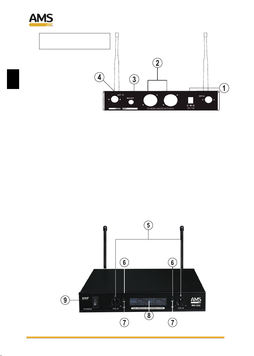
RECEIVER
(CONTROLS & FUNCTIONS)
1. DC POWER SUPPLY INPUT SOCKET
The receiver uses an external AC adapter (included), and must be connected to this
socket.
2. BALANCED XLR OUTPUT
For better quality reception, it is recommended to connect the mixer or amplifier to
these balanced XLR male sockets.
3. UNBALANCED JACK 1/4" OUTPUT
Jack 1/4" - jack 1/4" cable is supplied to connnect between the mixed output to the
amplifier or mixer.
4. ANTENNA
Each channel has its own antenna. Please, place them in 90º
EN
MU 302
User Manual / Manual de usuario
3
5. MICROPHONE (A & B) VOLUME CONTROLS
To adjust the volume control of each channel separately.
6. AF SIGNAL INDICATORS
It indicates the audio signal. As soon as signal is received, the AF LED will light up.
7. RF SIGNAL INDICATORS
It indicates RF signal received. As soon as signal is emmited from the microphones,
the RF LED will light up.
8. LCD DISPLAY
The display is separated for each channel, showing frequency, antenna, group and
channels parameter.
9. POWER ON/OFF SWITCH
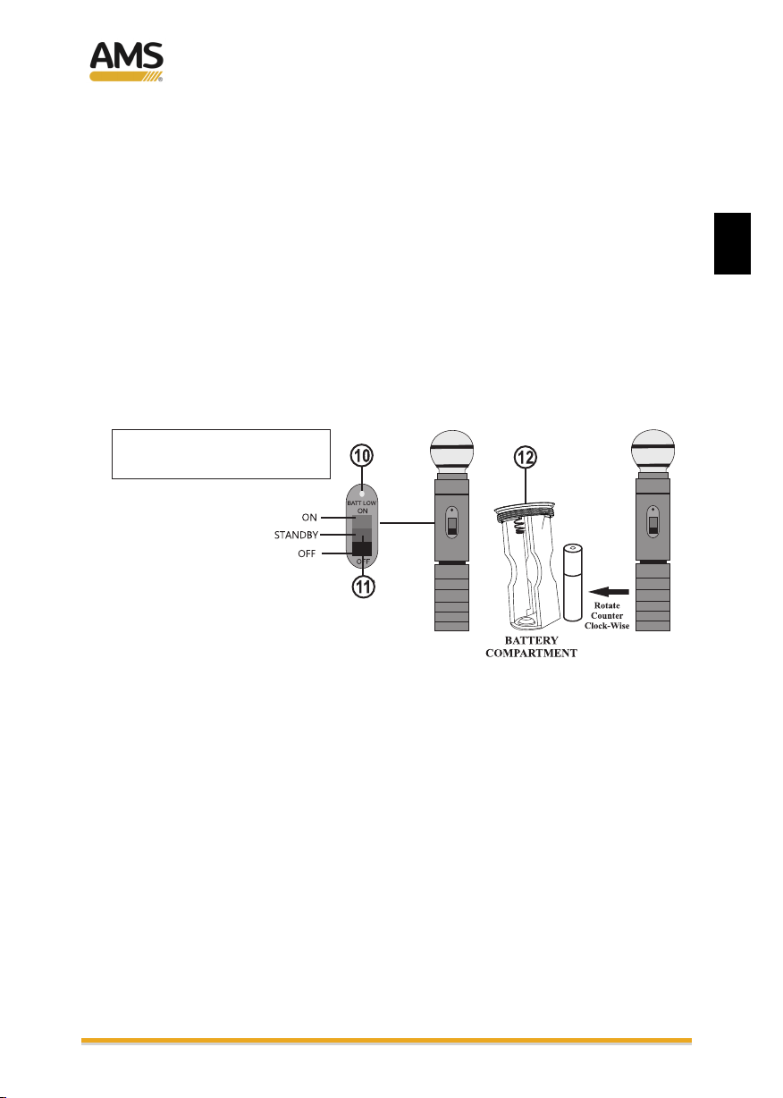
HANDHELD MICROPHONE
(CONTROLS & FUNCTIONS)
10. BATT LOW
When the batteries are weak, the LED comes on indicating that the batteries need to
be replaced. In normal operation, this LED will blink and go off
11. ON/OFF STANDBY SWITCH
This switch has 3 positions. The lowest point being OFF. The mid position being
on STANDBY function and the top position being on ON function.
12. BATTERY COMPARTMENT
Two 1.5V AAA type batteries must to be used. Be sure to place them in correct polarity
position.
MM 102
EN
MU 302

User Manual / Manual de usuario
4
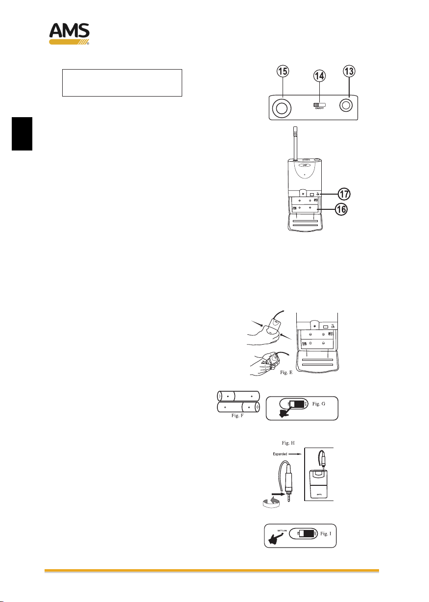
BODYPACK
(CONTROLS & FUNCTIONS)
13. MICROPHONE INPUT
Connect the supplied lavalier microphone
14. ON/OFF SWITCH
This switch has 2 positions. The lowest point being
OFF and the top position being on ON function.
15. ANTENNA
16. BATTERY COMPARTMENT
Two 1.5V AAA type batteries must to be used. Be sure
to place them in correct polarity position.
17. GAIN CONTROL
Use a small screwdriver and reduce or increase the
gain of the transmitter.
OPERATION
1. To access to the battery compartment,
push the cover downside (Fig. E)
2. Insert the batteries with correct
polarity. Before inserting them, be
sure that the power switch is
in OFF position. (Fig F)
3. After inserting the batteries, close the
housing sliding the cover. Pass the
switch to ON position. (Fig. G)
4. Insert the lavalier mic in the socket and
tighten the thread. (Fig H).
5. Switch off the power switch when the microphone
is not in use, meanwhile, remove the batteries out
of the transmitter if it is not in use for an extended
period.
ML 102
EN
MU 302

User Manual / Manual de usuario
INTRODUCCION
SEGURIDAD
1. Por favor, lea las notas de seguridad antes de operar la unidad.
CARACTERÍSTICAS DEL SISTEMA
DATOS TÉCNICOS
5
- Circuitería SMT
- 5 frecuencias disponibles que no interfieren entre ellas.
- 2 sistemas diferentes: con 2 micrófonos de mano o 2 petacas y micrófono lavalier.
- Salidas XLR balanceadas y salida Mixer desbalanceada con conector jack 1/4"
- Frequencia, grupo, antena y canal mostrado en la pantalla LCD
- Controles de volumen separado para ambos canales.
- Peso neto: 1.2 kg
Receptor
1. Modo de recepción: 2 canales
2. Rango de frecuencia: UHF 614-806MHz
3. Respuesta en frec.: 40Hz -18KHz(±3dB)
4. Estabilidad de la frec.: ±0.005%
5. Distorsión:
<0.5%
6. S/N: >105dB
7. Rechazo a espúreos : >80dB
8. Alimentación: 13 -15V DC
Petaca / micrófono
1. Modulación : FM3
2. Consumo : <110mA
3. Antena :incorporada
4. Directividad: cardioide
5. Oscilación de frec. : ±48KHz
6. : Rechazo a espúreos >60dB
Gracias por la adquisición de este sistema inalámbrico. Antes de usar el dispositivo, por
favor, lea el manual de uso cuidadosamente para entender cómo usar la unidad
correctamente.
Después de leerlo, guárdelo en un sitio seguro para futuras referencias.
2. Por favor, no sitúe la unidad en lugares con alto nivel de humedad o potentes campos
magnéticos. Además, evite la luz solar directa sobre la unidad. Si el producto no va
a ser usado durante un periodo prolongado de tiempo, por favor, desconecte el
alimentador y retire las pilas de los micrófonos y petacas.
3. Utilice únicamente el alimentador externo proporcionado junto con el receptor.
Confirme el voltaje de la toma mural antes de conectarlo.
4. No abra la tapa del receptor. Si la unidad deja de funcionar, contacte con su
distribuidor.
ES
9. Dimensiones: 210 x 150 x 35 mm
MU 302

User Manual / Manual de usuario
6
RECEPTOR
(CONTROLES y FUNCIONES)
1. CONECTOR DE ALIMENTACION DC
El receptor utiliza un alimentador AC externo (incluido), y debe ser conectado a esta
toma.
2. SALIDAS XLR BALANCEADAS
Para una mejor calidad de recepción, es recomendado utilizar estos conectores
para el conexionado al mezclador o amplificador (conector para cada canal)
3. SALIDA JACK 1/4" OUTPUT
Se suministra un cable Jack 1/4" - jack 1/4" para conectar la salida mezclada de
ambos canales.
4. ANTENA
Cada canal dispone de su propia antena. Por favor, sitúelas en un ángulo de 90º
para una mejor recepción.
ES
MU 302

User Manual / Manual de usuario
7
5. CONTROLES DE VOLUMEN (CANALES A y B)
Permiten ajustar el volumen de cada canal por separado.
6. INDICADORES DE SEÑAL AF
Indican la señal de audio. Tan pronto como se recibe la señal de audio, el LED AF se
encenderá.
7. INDICADORES DE SEÑAL RF
Indican la señal RF recibida. Tan pronto como el micrófono emita señal, el LED RF
se encenderá.
8. PANTALLA LCD
La pantalla está separada para cada canal, mostrando frecuencia, antena, grupo y
parámetros de cada canal.
9. INTERRUPTOR ON/OFF DE ENCENDIDO
MICROFONO DE MANO
(CONTROLES y FUNCIONES)
10. BATT LOW
Cuando las pilas están casi agotadas, el LED se enciende, indicando que las pilas
necesitan ser sustituidas. En el modo normal de funcionamiento, el LED se enciende
al ponerlo el marcha y se apaga rápidamente.
11. SELECTOR ON/OFF STANDBY
Este selector tiene 3 posiciones, en la parte inferior se apaga el micrófono, en el medio
pasa a modo standby y en la parte de superior se enciende.
12. PORTAPILAS
Se precisa dos pilas de 1.5V AAA. Asegúrese de colocarlas con la polaridad correcta.
PORTAPILAS
Girar en
sentido
antihorario
ES
MU 302
MM 102
User Manual / Manual de usuario
8
PETACA
(CONTROLES y FUNCIONES)
13. ENTRADA DE MICRÓFONO
Conecte el micrófono lavalier incluido
14. SELECTOR ON/OFF
Este selector tiene 2 posiciones. La inferior apaga
la petaca y la superior la enciende.
15. ANTENA
16. PORTAPILAS
Se precisa dos pilas de 1.5V AAA. Asegúrese de
colocarla con la polaridad correcta.
17. CONTROL DE GANANCIA
Use un destornillador pequeño para reducir o
incrementar la ganancia de la petaca.
FUNCIONAMIENTO
1. Para acceder al portapilas, deslice
la tapa. (Fig. E)
2. Inserte las pilas con la polaridad
correcta. Antes de insertarlas,
asegúrese que el interruptor
está apagado (Fig F)
3. Después de insertar las pilas, cierre
el portapilas deslizando la tapa.
pase a ON el interruptor de
encendido (Fig. G)
4. Inserte el micro lavalier en la toma y
apriete la rosca. (Fig H).
5. Apague la alimentación cuando no se use
el micrófono, además, retire las pilas de la
petaca si no va a usar la unidad durante
bastante tiempo.
ES
MU 302
ML 102


CIF: B-96894308
Av.Saler nº6 – Polig. Ind. L´Altero
46460 Silla ( Valencia – España )
Tel: +34 963 124 088- Fax: +34 963 219 645
Table of contents
Languages:
Popular Microphone System manuals by other brands


Nady Systems
Nady Systems ENCORE 200 owner's manual

Audio Technica
Audio Technica ATCS-60 instruction manual

Retekess
Retekess TT106 instructions

Lectronics
Lectronics Freedomike Performer Operation manual

US Blaster
US Blaster USB 7393 owner's manual

Worldcast Systems
Worldcast Systems SOLAR FM Quick Start Notice