Audiophonics RASPTOUCH ES9023 User manual

RASPTOUCH
Open source network player: Raspberry Pi 3 & DAC
User Manual –Kit DIY
ES9023 or ES9018K2M

We hope you will enjoy our open source network player, the Rasptouch. Read this installation
manual thoroughly before using it. To avoid any erroneous manipulation an to protect you and the
device from possible dammages caused by inadequate use, we invite you to follow step by step
the assembly of the case, the mounting of the screen support and the toutchscreen.
Please keep the installation manual for future reference.
RASPTOUCH
Before starting…
Page 1 sur 29
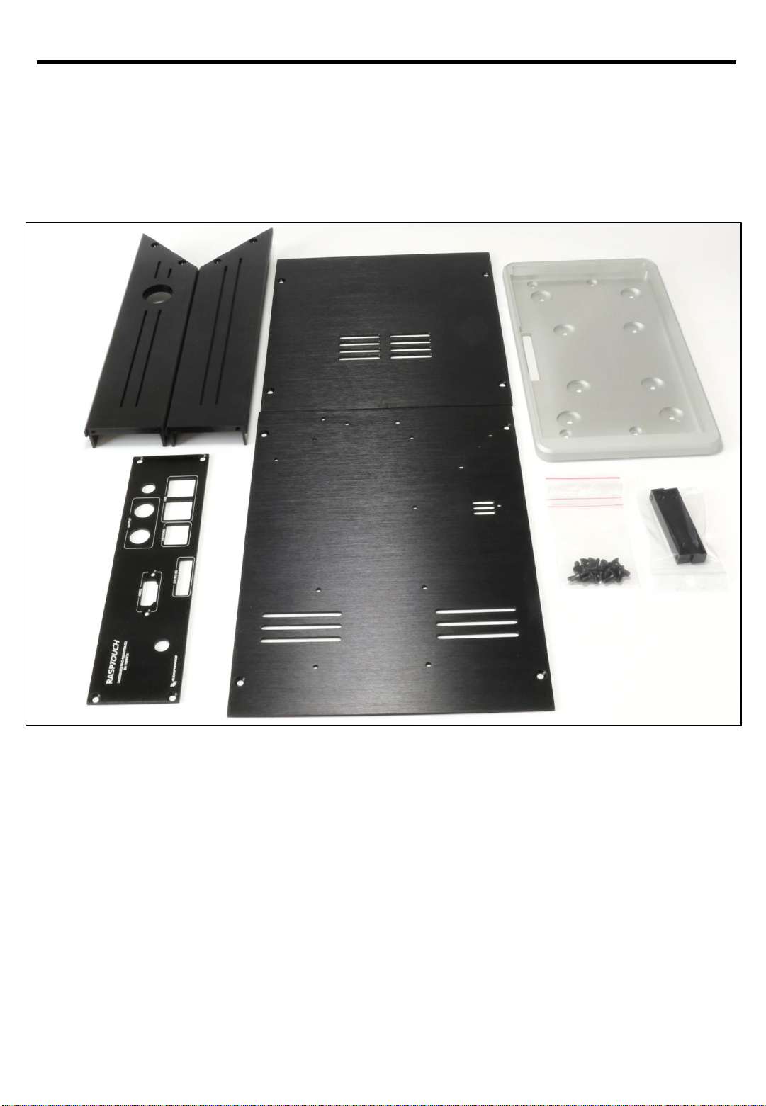
In the package you will find many plastic bags containing different elements. To assemble the case
and the display support select the following pieces:
RASPTOUCH
1 –Elements necessary for mounting the case and the display support…
Display support (Black and silver)
Cover
Bottom (all the holes to fixe all the components)
Left Side (Botton hole)
Right Side
Back pannel
20 screws bag M3x4mm (PH2 compatible)
2 metal pieces for the display support
Page 2 sur 29
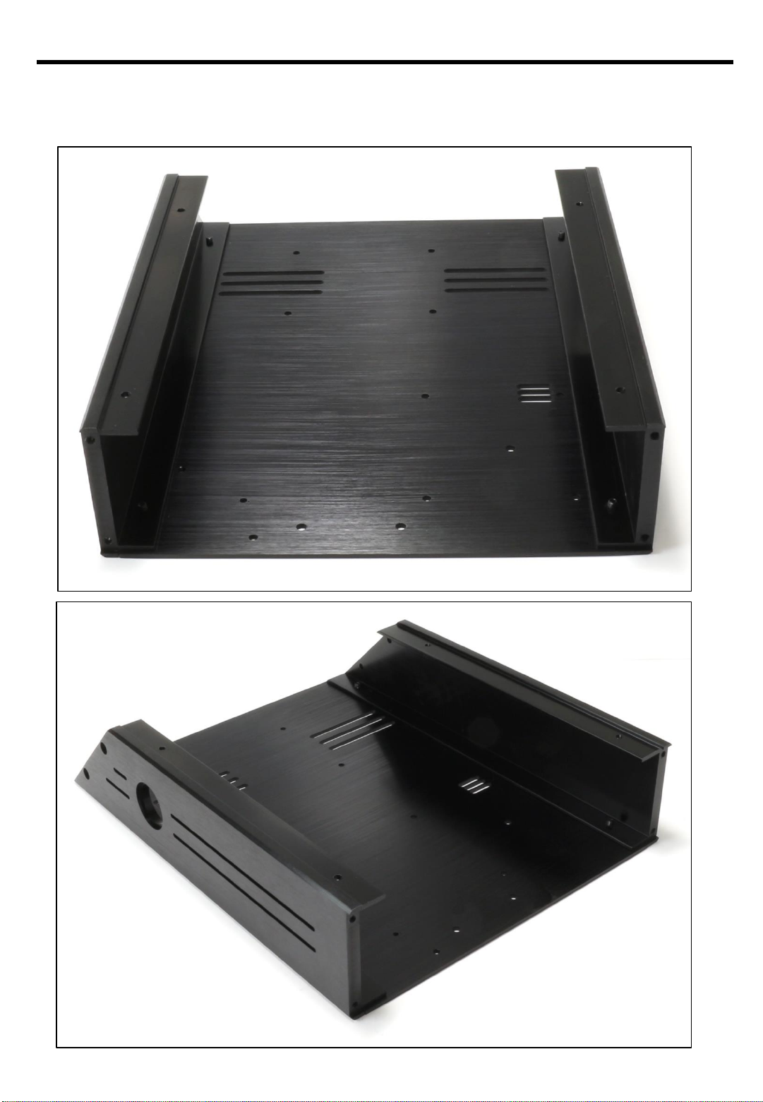
First step, mounting both sides on the bottom plate with 4 screws.
RASPTOUCH
2 –Assembling the two sides…
Page 3 sur 29
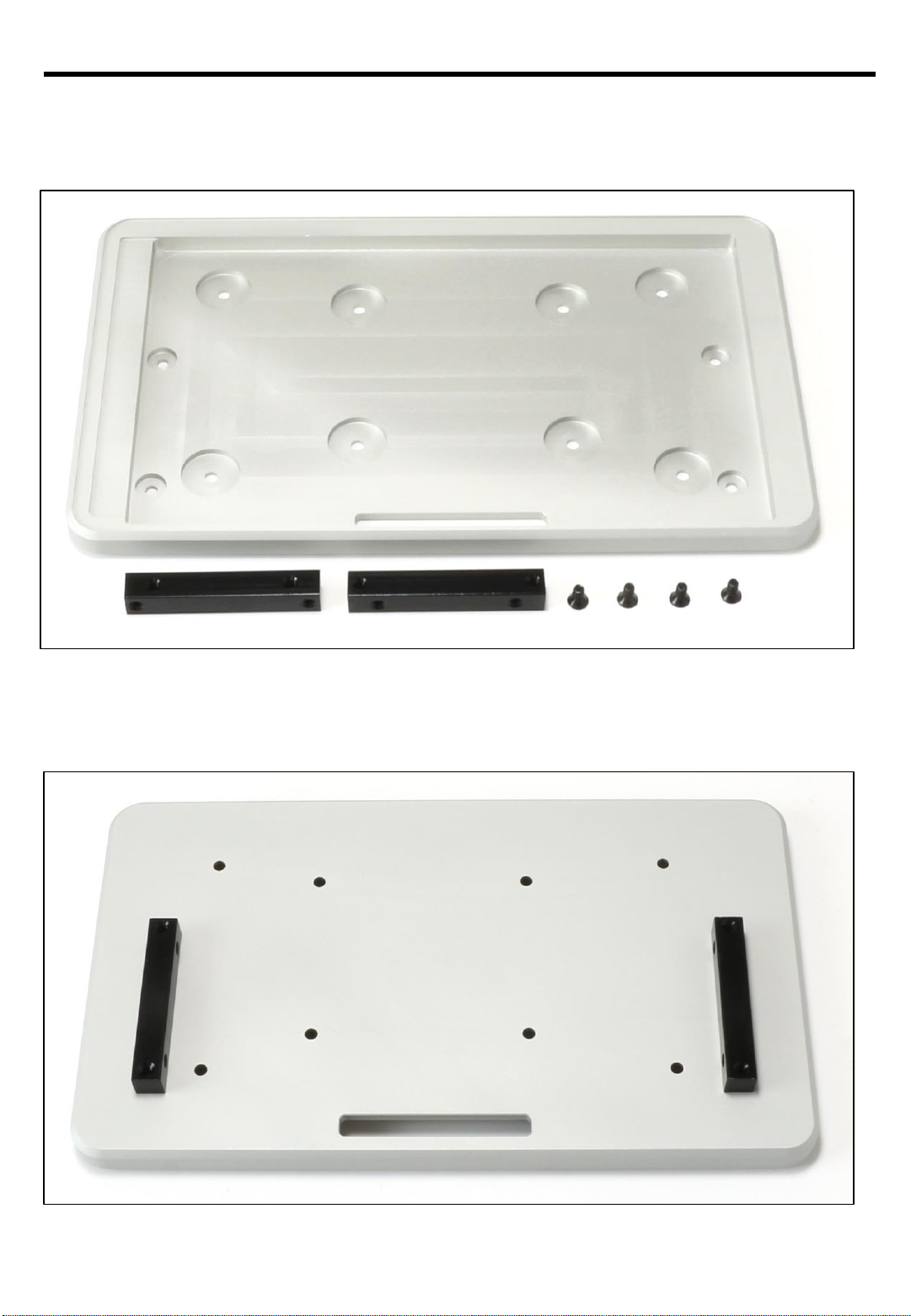
Select the following elements:
RASPTOUCH
3 –Display support…
Screw the two holding bars onto the support as in the picture:
Page 4 sur 29

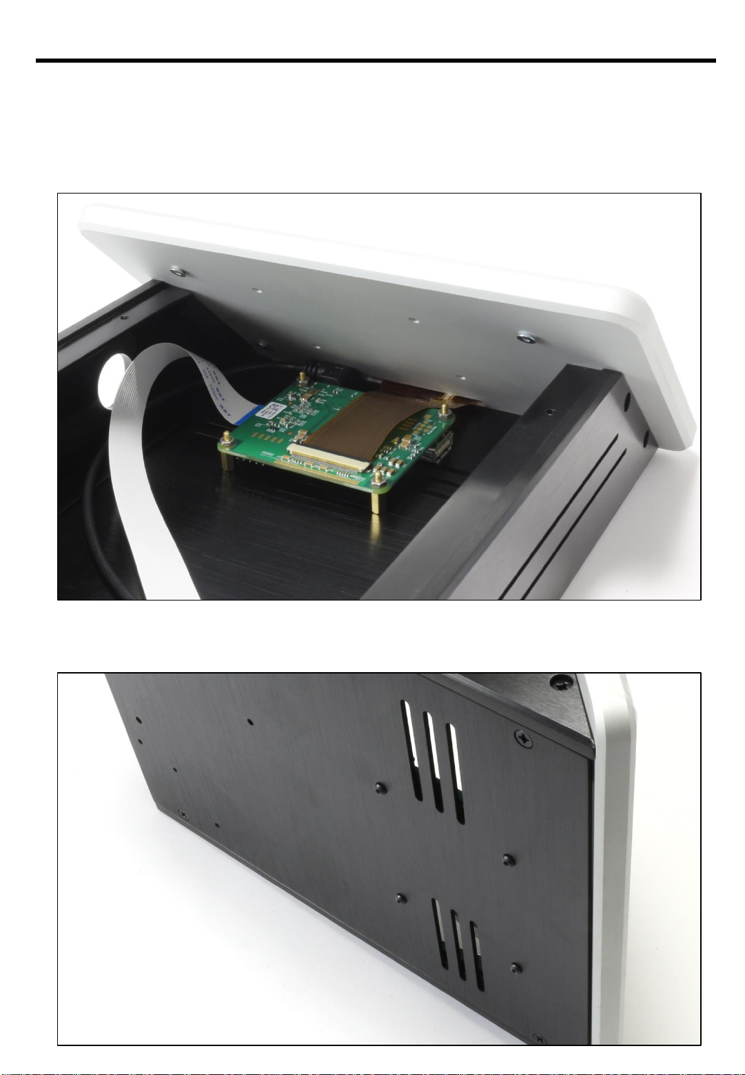
Fit the display support to the front of the pre-assembled case, then screw the 2 holding bars from
the outside, the final result should like the picture bellow.
RASPTOUCH
4 –Assembling the display support…
Inside vue…
Page 5 sur 29

With the help of another 4 screws just screw them like the photo:
RASPTOUCH
5 –Back panel…
It should remain 8 screws, 4 that go to the top cover and 4 others for the display.
Once you have the official Raspberry Pi 7 ’’ display, unscrew the pre-assembled display support.
To start, mount the display on the support with the help of the 4 screws.
Then use the 4 M2.5x8mm spacers and the HU Inox A2 M2.5x2mm nuts for the display PCB.
Connect the Display interconnect cable (blue marker like the photo) , as well on of two USB power
cables, once again check the picture in the next page for reference:
6 –Montage de l’écran sur le support d’écran
Page 6 sur 29
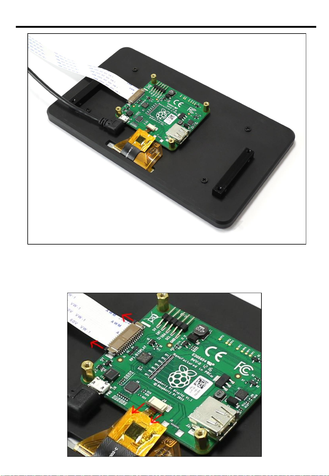
RASPTOUCH
Pay close attention to how you connect the screen o the PCB. Gently unlock the plastic wedge
(please check the following picture). Once again please check if all the interconnect cables are like
in the picture.
Page 7 sur 29
As in the step 4, the holding bars should be screwed from the outside (if necessary please refer
again to the step 4).
Alayw pay close attention to avoid deconnecting the interconnect cables.
RASPTOUCH
7 –Assembling the display with the support…
Screw the display PCB with the help of the M2.5x5mm screws like the photo:
Page 8 sur 29

RASPTOUCH
8 –Extension Micro SD, Extension HDMI & push button…
Select the following elements to continue to the next step
Push button
HDMI Extension
Micro SD Extension
Micro SD Extension reader support bar
HU Acier M2 Nuts + THFC M2x16mm Screws
Page 9 sur 29
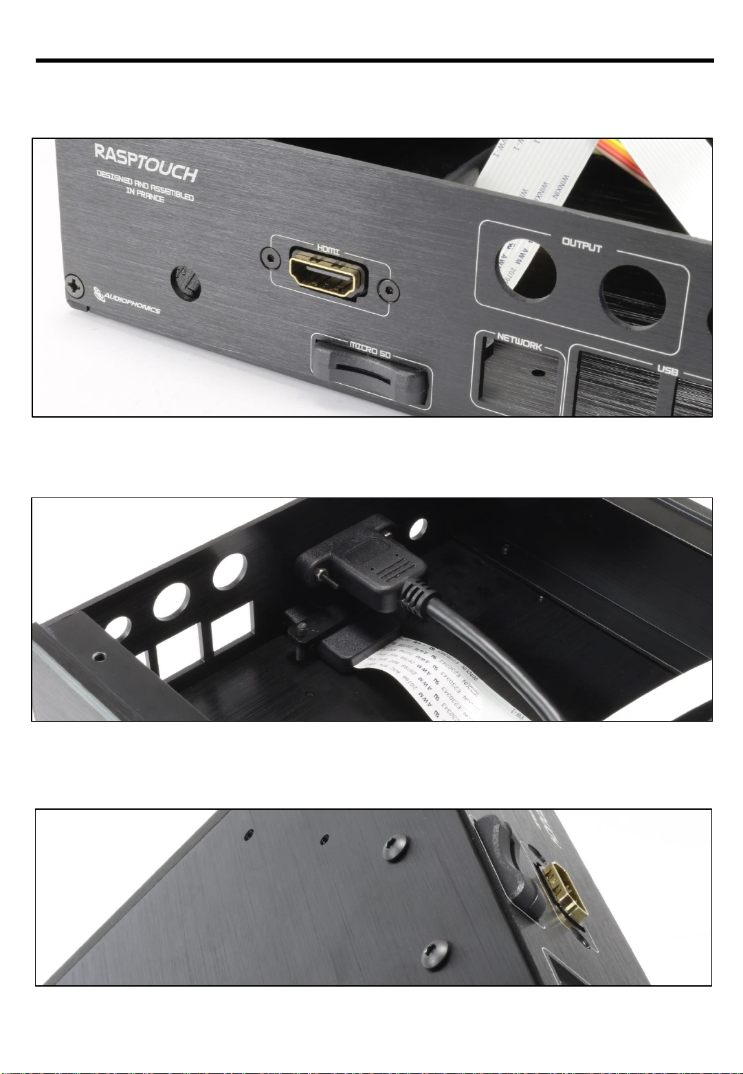
RASPTOUCH
Once in place the, the HDMI and the Micro should present them like the photo bellow:
Please screw the screws and nuts like the photo, including the Micro SD Reader metal bar
Keep in mind the Micro SD card reader are fixed using the two screws like the exemple bellow.
Page 10 sur 29

RASPTOUCH
For the power button, you need to remove the nut and then insert him in the hole. Use the nut to
place the button in the right position like the photo.
Don’t forget to turn the button until he is in the right position. It should looke like the example
bellow:
Page 11 sur 29
RASPTOUCH
DAC ES9023
Page 12 sur 29

RASPTOUCH
To start, take the smal bag including the 2 squares of thermal paste, their holding plate as well the
screw. Place the holding plate and the screw (turn the case and screw from the bottom), then
place the thermal paste. It should look as in this picture:
9 –Thermal paste + holding plate…
The Raspberry Pi wiil then stick to it. The location is provided so that it lands perfectly where the
heat is to be dissipated. (Please dont forget to remove the protection from the thermal paste.)
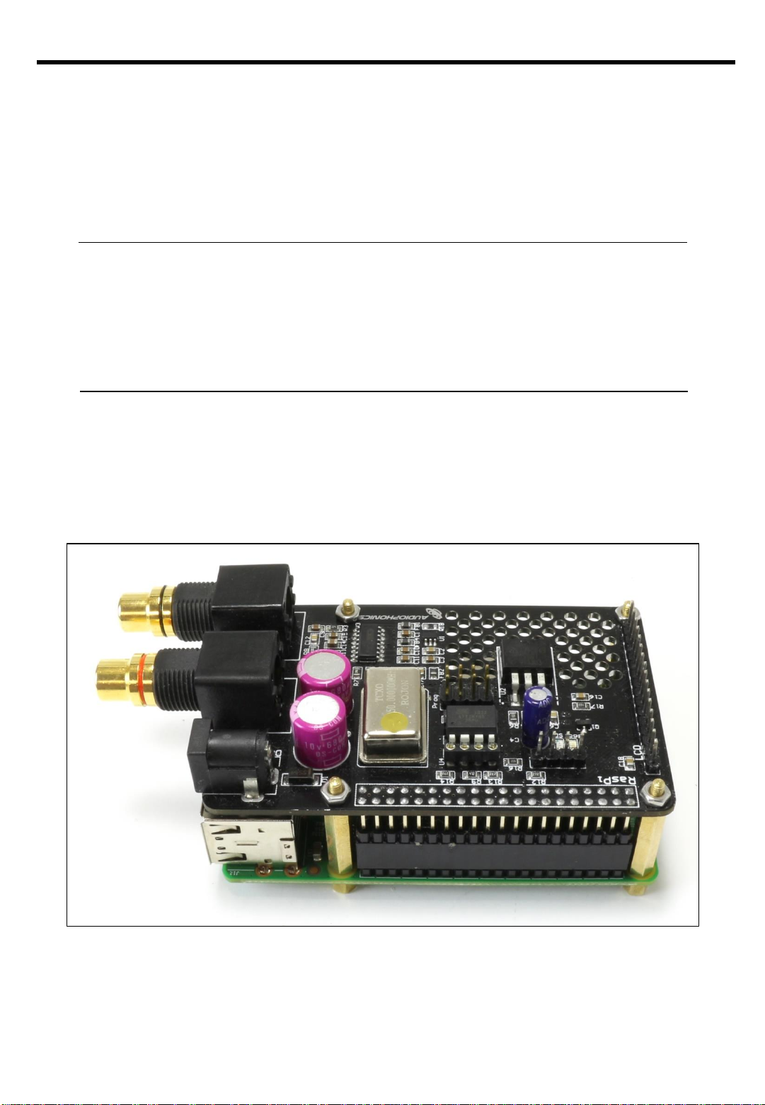
10 –« Raspberry Pi + DAC ES9023»…
Once the Raspberry Pi and the ES9023 DAC are in your hands, it is necessary to assemble both in
order to integrate them in the case later.
O assemble the Raspberry Pi and the DAC, retrive the spacers and the nuts found in your package,
assemble the whole as in the following picture:
Page 13 sur 29

RASPTOUCH
Do not be affraid to toghten the screws and spacers, the goal is that the two parts become stable
and fixed together.
Page 14 sur 29
RASPTOUCH
10 –« Raspberry Pi + DAC ES9023 in the case…
Once the you have finished the previous step you will be able to integrate the Raspberry Pi and
the DAC in the case in te location provided for withe all the holes located loke in the picture.
The assembly is screwed by the bottom of the case withe 4 screws TBHC M2,5x5mm as in the
picture (the screw of the center is for the termal paste holding plate)
Page 15 sur 29
RASPTOUCH
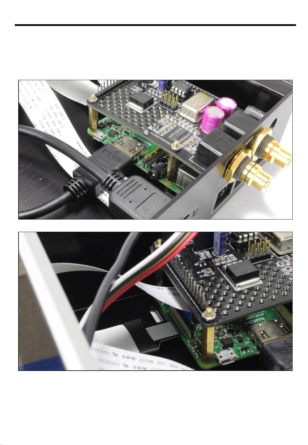
11 –Connecting various accessories to Raspberry Pi…
Once teh Raspberry Pi and DAC are integrated into the case, you can connect the various pre
assembled accessories and cables: HDMI extension cable, Micro SD Extension Cable and the
Touchscreen interconnection, as in the following pictures:
Be careful when inserting the interconnecting cable into the slot on the Raspberry Pi (blue side
towards the outside of the PCB), as well as the micro SD extension that "snaps" into the underside
of the PCB.
Page 16 sur 29

RASPTOUCH
To connect the PCB of the Raspberry display and the push button to the DAC for power supply, be
sure to mark the wires and colors and connect them exactly as shown in the following picture:
•Pushbutton: the 2 pins on the inside, on the right side of the PIN (Insert "Button" on the PCB) /
The other 2 wires for the LED (external pins) on the left side of the PIN.
•PCB of the Raspberry screen via micro USB cable: On the 2 outermost PINs to the right of the
GPIO return, the red wire ALWAYS to the left of the black wire.
Page 17 sur 29
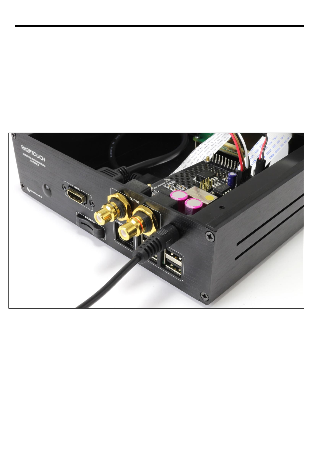
RASPTOUCH
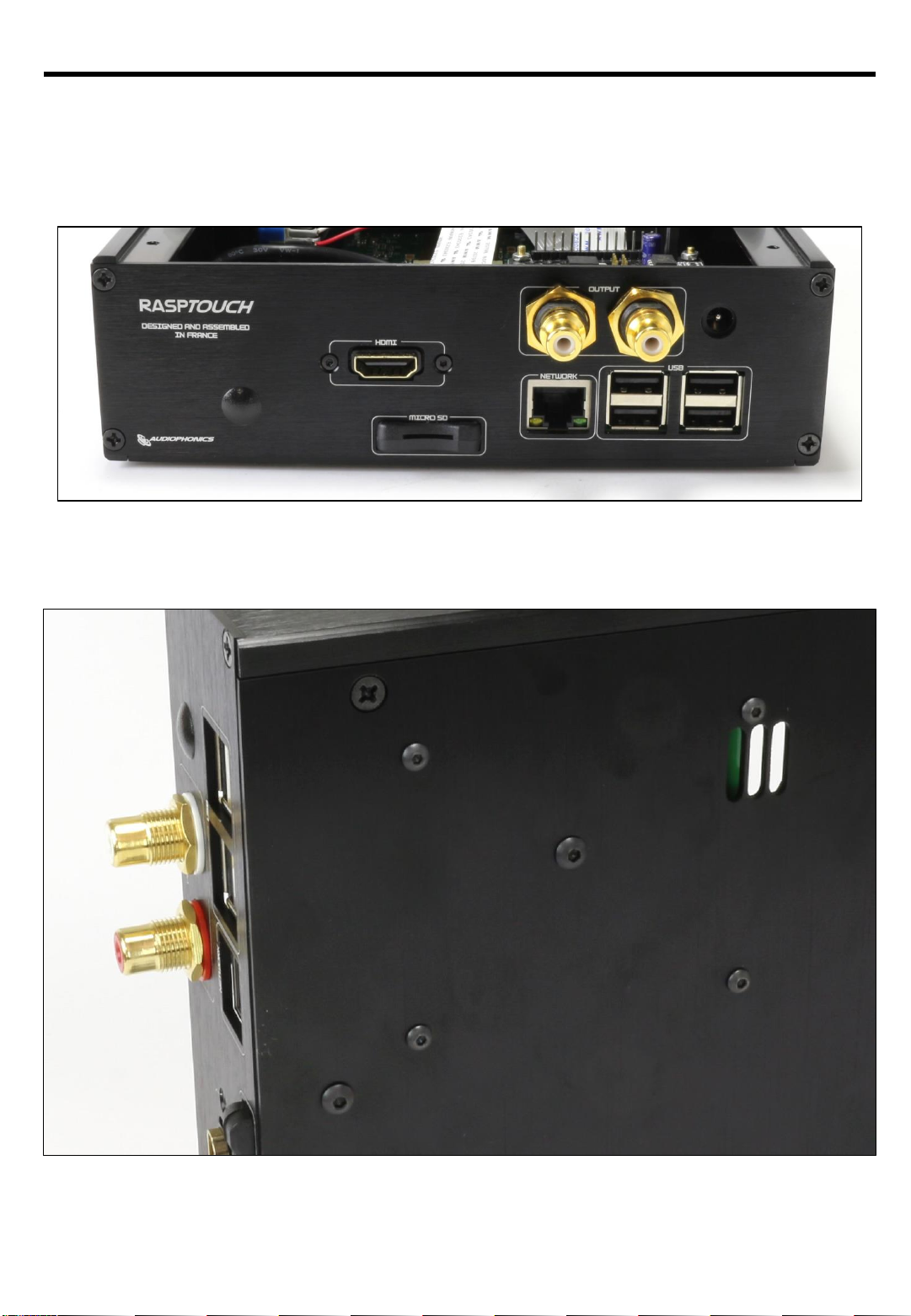
12 –Power supply of the Rasptouch with DAC ES9023…
The entire system is powered by the AC adapter (6,5 à 7V / 2A) you received in your package.
Indeed, the jack present on the ES9023 DAC is accessible from the back panel (see picture below),
and you will be able to feed all the components:
•DAC ES9023
•Raspberry Pi
•Official Raspberry Pi Screen (via PCB)
•Push Button with LED
Page 18 sur 29
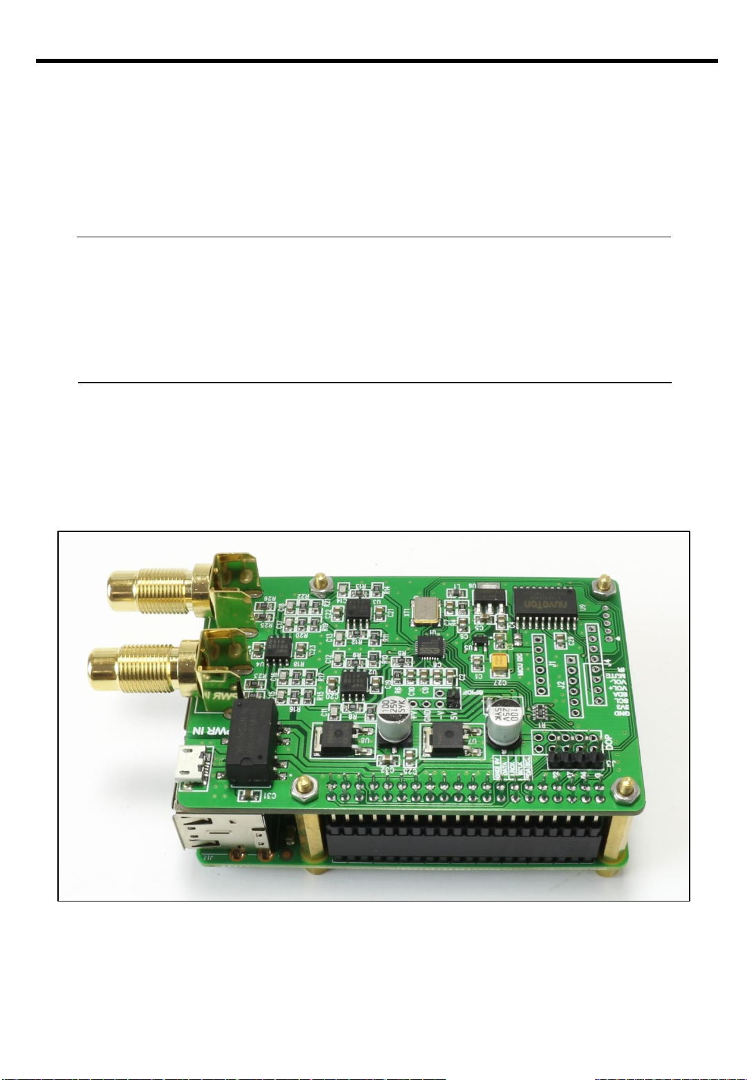
RASPTOUCH
DAC ES9018K2M
Page 19 sur 29
This manual suits for next models
1
Table of contents
Other Audiophonics Media Player manuals


Popular Media Player manuals by other brands

Bluesound
Bluesound powernode 2 owner's manual

Emtec
Emtec Movie Cube Movie Cube 40GB user manual

Bluesound
Bluesound Node 2 Assembly instructions

Blackboxav
Blackboxav VideoClip-HD user manual

Silvercrest
Silvercrest SMRA 5.0 A1 Operating instructions and safety instructions

Goldmund
Goldmund EIDOS 36D user manual


