audiophony LIVEtouch20 User manual
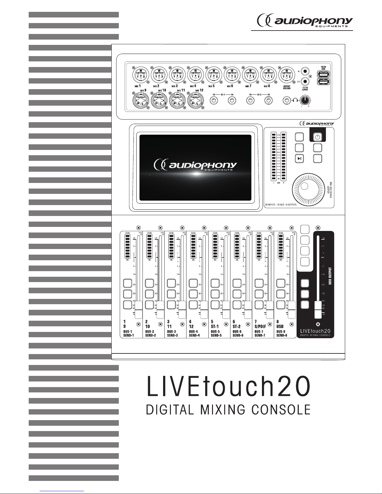
USER GUIDE
H10901 - Version 1 / 10-2018
COPY
SETUP
BACK
PASTE
IN
1-8
BUS
1-8
SENDS
IN
9-20
SOLO
M
SEL
SOLO
M
SEL
SOLO
M
SEL
SOLO
M
SEL
SOLO
M
SEL
SOLO
M
SEL
SOLO
M
SEL
SOLO
M
SEL
SOLO
M
SEL
Page 2
LIVEtouch20 - 20 Channel Digital Mixing Console
English
1 - Please read carefully :
We strongly recommend to read carefully and understand the safety instructions before
attempting to operate this unit.
2 - Please keep this manual :
We strongly recommend to keep this manual with the unit for future reference.
3 - Operate carefully this product :
We strongly recommend to take into consideration every safety instruction.
4 - Follow the instructions:
Please carefully follow each safety instruction to avoid any physical harm or property
damage.
5 - Avoid water and wet locations :
Do not use this product in rain, or near washbasins or other wet locations.
6 - Installation :
We strongly encourage you to only use a fixation system or support recommended
by the manufacturer or supplied with this product. Carefully follow the installation
instructions and use the adequate tools.
Always ensure this unit is firmly fixed to avoid vibration and slipping while operating
as it may result in physical injury.
7 - Ceiling or wall installation :
Please contact your local dealer before attempting any ceiling or wall installation.
8 - Ventilation :
The cooling vents ensure a safe use of this product, and avoid any overheating risk.
Do not obstruct or cover these vents as it may result in overheating and potential
physical injury or product damage. This product should never been operated in a
closed non-ventilated area such as a flight case or a rack, unless cooling vents are
provided for the purpose .
9 - Heat exposure :
Sustained contact or proximity with warm surfaces may cause overheating and product
damages. Please keep this product away from any heat source such as a heaters,
amplifiers, hot plates, etc...
1 - Safety information
This symbol signals an important safety precaution.
The CAUTION symbol signals a risk of product deterioration.
The WARNING symbol signals a risk to the user’s physical integrity.
The product may also be damaged.
Important safety information
Symbols used
Any maintenance procedure must be performed by a CONTEST
authorised technical service. Basic cleaning operations must tho-
roughly follow our safety instructions.
This product contains non-isolated electrical components. Do not
undertake any maintenance operation when it is switched on as it
may result in electric shock.
This unit is intended for indoor use only. Do not use it in a wet, or
extremely cold/hot locations. Failure to follow these safety instruc-
tions could result in fire, electric shock, injury, or damage to this
product or other property.
WARNING : This unit contains no user-serviceable parts. Do not open the
housing or attempt any maintenance by yourself. In the unlikely even your unit may
require service, please contact your nearest dealer.
In order to avoid any electrical malfunction, please do not use any multi-socket, power
cord extension or connecting system without making sure they are
perfectly isolated
and present no defect.
Recycling your device
• As HITMUSIC is really involved in the
environmental cause, we only commercialise
clean, ROHS compliant products.
• When this product reaches its end of life,
take it to a collection point designated by local
authorities. The separate collection and recycling
of your product at the time of disposal will help
conserve natural resources and ensure that it is
recycled in a manner that protects human health
and the environment.
Instructions and recommendations
10 - Electric power supply :
This product can only be operated according to a very specific voltage. These
information are specified on the label located at the rear of the product.
11 - Power cords protection:
Power-supply cords should be routed so that they are not likely to be walked on or
pinched by items placed upon or against them, paying particular attention to cords at
lugs, convenience receptacles and the point where they exit from the fixture.
12 - Cleaning precautions :
Unplug the product before attempting any cleaning operation. This product should be
cleaned only with accessories recommended by the manufacturer. Use a damp cloth
to clean the surface. Do not wash this product.
13 - Long periods of non use :
Disconnect the unit’s main power during long periods of non use.
14 - Liquids or objects penetration :
Do not let any object penetrate this product as it may result in electric shock or fire.
Never spill any liquid on this product as it may infiltrate the electronic components
and result in electric shock or fire.
15 - This product should be serviced when :
Please contact the qualified service personnel if :
- The power cord or the plug has been damaged.
- Objects have fallen or liquid has been spilled into the appliance.
- The appliance has been exposed to rain or water.
- The product does not appear to operate normally.
- The product has been damaged.
16 - Inspection/maintenance :
Please do not attempt any inspection or maintenance by yourself. Refer all servicing
to qualified personnel.
17 - Operating environment :
Ambient temperature and humidity: +5 - +35°C, relative humidity must be less than
85% (when cooling vents are not obstructed).
Do not operate this product in a non-ventilated, very humid or warm place.
Sound levels
Our audio solutions deliver important sound pressure levels
(SPL) that can be harmful to human health when exposed
during long periods. Please do not stay in close proximity
of operating speakers.

Page 3
LIVEtouch20 - 20 Channel Digital Mixing Console English
2 - General and technical data
Features
12 microphone input + 2 stereo inputs
1 S/PDIF input/output and 1 AES/EBU output
4 mono busses / 5 stereo busses / 1 monitor bus
8 assignable XLR outputs
1 stereo monitor output and 1 headphone output
1 x 7" touch screen
8 effect modules
2 USB plugs for song recording, song playback and scene backups
Technical data
Inputs 12 microphones (4 Combo), 2 stereo, S/PDIF and USB
Input channel functions Phase, Delay, high pass filter, 4 band parametric equalizer, noise
gate, compressor, pan, effects
Outputs 8 assignable XLR, AES/EBU, S/PDIF and headphone
Internal signal generator White, sinusoidal and white noise
Phantom power 48V independently activatable on each channel
USB Features Play and record songs, system update, scene backup and external
network card
Screen 7-inch, 1024 x 600 pixel, high definition touchscreen
AD/DA 192 KHz/24 bits max.
Sampling frequency 48 KHz / 44.1 KHz
DSP SHARC ADI 40-bit floating point processor, 4th generation, 450M
Effects 8 modules: 2 Reverbs, 2 Modulation, 2 Delay and 2 x15 bands
graphic equalizers
Système Custom Android
Network Via 1 external USB module (supplied)
Remote control Via 1 iPad application
Power supply 100-240V 50/60Hz > DC12V
Size 445 x 325 x 100 mm
Weight 5.3 Kg
Packaging content
The LIVEtouch20 console
1 external power supply
1 IEC power cord
1 WiFi dongle
The user guide

Page 4
LIVEtouch20 - 20 Channel Digital Mixing Console
English
3 - Overview of the unit
3-1 Front panel connection system
3-2 Main module
1 4
2 3 6
5
1 - 8 XLR mic inputs
2 - 4 combo mic inputs
3- 2 jack stereo inputs
4 - S/PDIF input/output and AES/EBU output connectors
5 - 2 USB inputs
6 - Pre-listening output with level adjustment
COPY
SETUP
BACK
PASTE
1 2
3
4
5
Page 5
LIVEtouch20 - 20 Channel Digital Mixing Console English
1 - 7-inch touch screen
2 - 6 bands master vu-meter
3- 5 control buttons
-SETUP : Provides access to system settings
-BACK : Lets you exit the system menu
-COPY and PASTE : Allows to propagate parameters from one channel to another
-PLAY/PAUSE : Manage USB source playback
4 - POWER button
- Press and hold for more than 3 seconds to turn the console off or on.
- ress this button for 1 second to lock all controls
5 - Adjustment knob
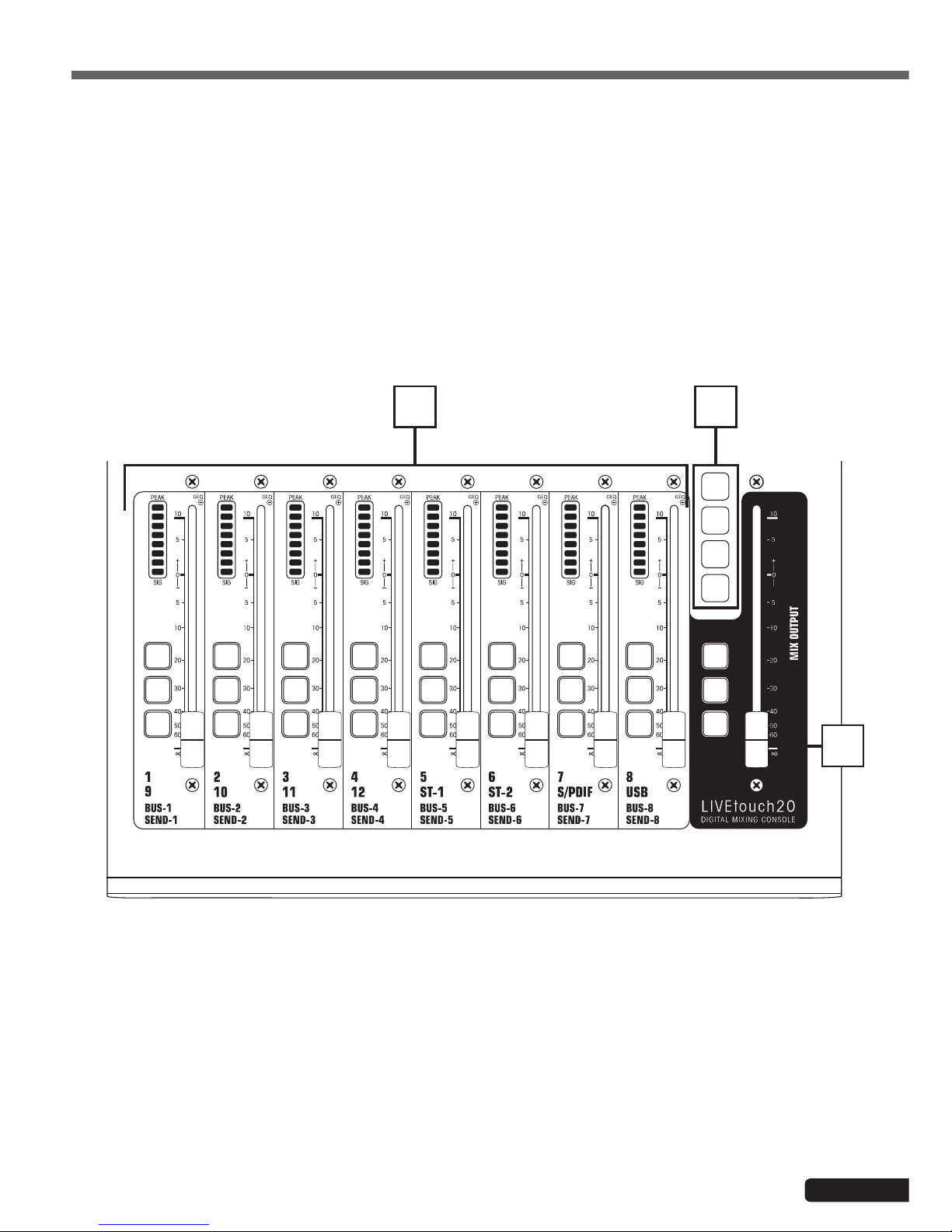
1 - Channels faders
- This section includes the 8-band channel VU meter, SEL (channel selection), SOLO (channel preview), M (channel
mute and bus assignment) and 100mm motorized faders.
2- Pages selectors
- "IN 1-8" button : Selects mono channels 1 to 8.
- "IN 9-20" button : Selects mono channels 9 to 12, stereo channels 1 and 2, S/PDIF input and USB input
- "BUS 1-8" button : Selects mono outputs 1 to 6 and stereo outputs 7 and 8.
- "SENDS" button: Used to select, for each bus, the channels that will be injected to outputs 1 to 8.
3 - MASTER section
- This section allows you to adjust the level of outputs 7 and 8.
IN
1-8
BUS
1-8
SENDS
IN
9-20
SOLO
M
SEL
SOLO
M
SEL
SOLO
M
SEL
SOLO
M
SEL
SOLO
M
SEL
SOLO
M
SEL
SOLO
M
SEL
SOLO
M
SEL
SOLO
M
SEL
2
3
1
3-3 Faders section

Page 6
LIVEtouch20 - 20 Channel Digital Mixing Console
English
1 - Power supply input : DC12V - 4,17A
2- Monitor output
- 6.35 Jack stereo output.
3 - 1 to 8 outputs
- Balanced outputs on XLR plugs.
3-4 Rear pannel
321

Page 7
LIVEtouch20 - 20 Channel Digital Mixing Console English
4-1 Inputs channels
4-1-1 Mic inputs
4 - Advanced Features
LIVEtouch20 console features 12 mono inputs, 2 analog stereo channels, 1 S/PDIF input and 1 USB input.
A MIC input channel contains five individual modules: Input stage, Equalizer, Dynamic, Send to bus and Output stage. A
simple click on a module will bring up a subpage with other options. Subpages can be closed with the red "close" button
in the upper right cornerB.
1
2
3
4
5
1 - Input Stage
Indicates the status of 48V phantom power, phase, delay, high pass filter and effects.
2- EQ
Displays the current equalization and allows access to the settings.
3 - Dynamics
Displays compressor and noise gate status and provides access to settings.
4 - Busses sends
Displays the buses to which the slice is sent and allows access to the bus selection.
5 - Output
Displays channel name, pan setting, preview (SOLO), MUTE and channel level .
Page 8
LIVEtouch20 - 20 Channel Digital Mixing Console
English
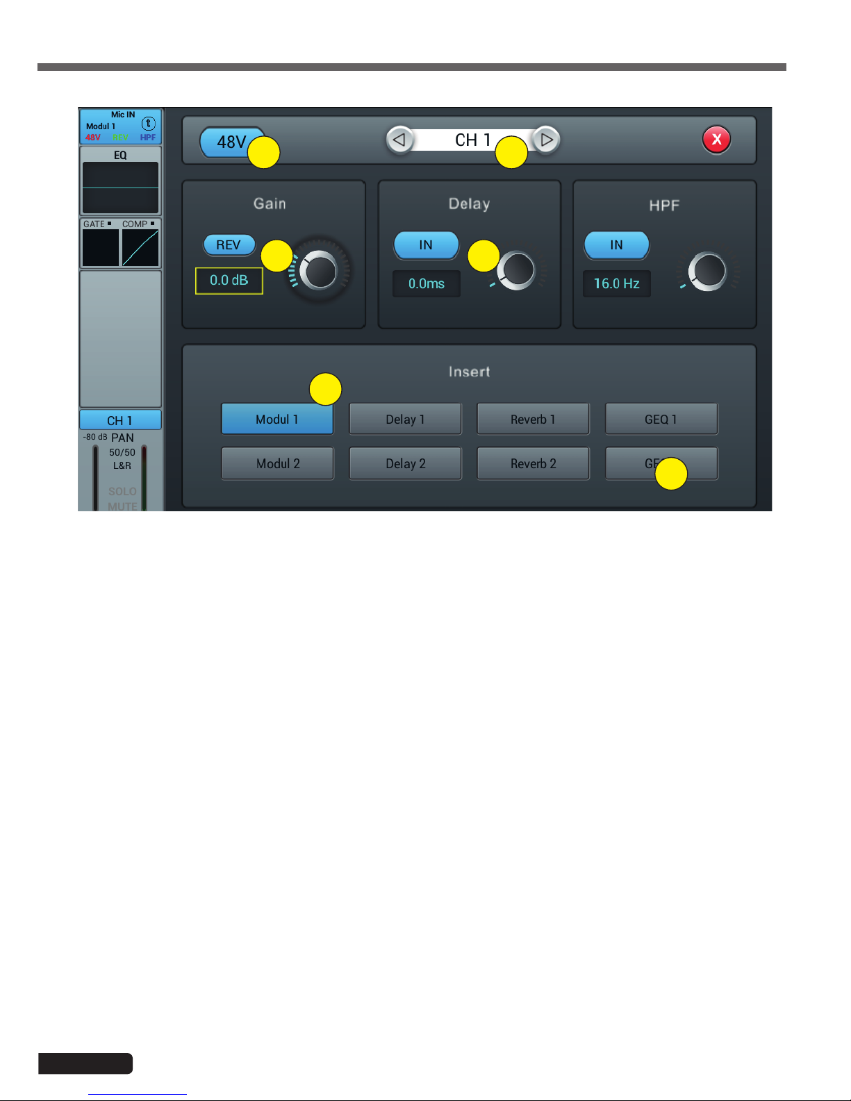
1 - Alimentation fantôme 48V
Active ou désactive l'alimentation fantôme sur le canal en cours.
2- Channels selector
Allows you to switch from one channel to another while remaining on the same page.
3 - Rev
Enables phase reversal. By default phase reversal is inactive.
4 - Delay
Enables Delay, by default Delay is disabled. The time can be set either via the setting wheel or directly on the
display. For fine adjustment, hold down the knob.
The time range is from 0 ms to 200 ms.
5 - HPF
Enable the high pass filter, by default the high pass filter is disabled. The frequency can be set either via the set-
ting wheel or directly on the display. For fine adjustment, hold down the knob.
Frequency is adjustable from 16 Hz to 400 Hz, default is 16 Hz.
6 - Insert
Press one of the buttons on the effect module to insert it before equalizing the channels. Each effect module can
only be inserted in one place and the input channels allow only one effect module to be used. When a selected
module is used in another channel or bus, a pop-up window appears: "The module can only be used once and is
already used by xxx. Do you want to use the force module now? Yes / No".
To change the effect settings, press the SETUP button, then press FX and click a module to open a dialog box for
the effect.
4-1-2 Subpage of the mono channel input stage
1 2
34
5
6

Page 9
LIVEtouch20 - 20 Channel Digital Mixing Console English
1- Channels selector
Allows you to switch from one channel to another while remaining on the same page.
2- Bypass
Enables or disables the equalizer on the current channel. By default the equalizer is active.
3 - Flat
Allows the equalizer to be flat again. This action is irreversible, the settings will be lost.
4 - 4-band EQ graph
The four points on the curve indicate the position of each parametric equalizer. You can select each point to adjust
the equalization. When a point is selected you can also adjust its equalization via insert 6 (frequency, gain and
Q-band width).
5 - Curve point selection keys
Use these keys to move from one point to another.
6 - Réglages de chaque point
These three potentiometers allow the adjustment of the points via the main encoder:
-Gain : Adjustable from -18dB to +18dB.
-Frequency : Each band can be set to a value between 20 Hz and 20 kHz. The default values are : HF 4kHz, HMF
1kHz, LMF 200 Hz, LF 60Hz. The terms HF, HMF, LMF and LF refer only to the initial band setting; there are no
restrictions in the equalizer band setting, so that after the setting, LF may actually be at the top of the frequency
range.
-Q: allows you to adjust the bandwidth from 0.5 (wide) to 10.0 (narrow). The default value is 0.5.
7 - Library
The library allows you to save and load the user's EQ settings. Click the drop-down menu and select a library
entry from the list to load its settings. Click the "Save" button and select the desired library location (1 - 16) from
the list to save the current equalizer settings. A virtual keyboard will appear on the screen to enter a name for the
setting. Finally, click "confirm" to save the setting or "cancel" to cancel.
4-1-3 Parametric equalizer sub-page
1 3
4
6
7
5
2

Page 10
LIVEtouch20 - 20 Channel Digital Mixing Console
English
1- Channels selector
Allows you to switch from one channel to another while remaining on the same page.
2- Side chain
This function allows you to use the signal from another channel to control the compression of the selected
channel. This can be useful when channel groups are used for a single instrument (for example, drums) to ensure
consistency of compression of all channels within the group. Click the drop-down button and select the channel
to use as the "Side chain" to control the active channel. The selection also allows you to switch between Pre and
Post equalization modes.
3 - Gate
IN : Enables the Gate to be activated. It is inactive by default.
Curve : The curve is divided into 3 parts - Attack (left), Hold (middle) and Release (right).
The threshold is indicated on the Y axis while the X axis indicates the relative time for each section.
Settings parameters : The curve is divided into 3 parts - Attack (left), Hold (middle) and Release (right).
The threshold is indicated on the Y axis while the X axis indicates the relative time for each section.
Threshold : The threshold varies from -80 dB to 0 dB with default -80dB. Any signal below the threshold will be
muted, so that the signal level must exceed the threshold to pass the noise gate.
Hold : (hold time) : From 2 ms to 2000 ms with default 2 ms.
Attack : (attack time) : Range 0.5 ms to 100 ms, default 3 ms.
Release : (temps de relâchement) : peut être ajusté de 2 ms à 2000 ms, par défaut 350 ms, ce qui est compatible
avec la plupart des sources sonores.
Depth : (release time) : can be adjusted from 2 ms to 2000 ms, default 350 ms, which is compatible with most
sound sources.
4-1-4 Dynamics sub-page
1
5
3
4
6
2

Page 11
LIVEtouch20 - 20 Channel Digital Mixing Console English
4 - Compressor
IN : Activates the compressor. It is inactive by default.
Courbe : The curve shows the gain relationship between the input and output signals. The curve is divided into
two parts - below and above the threshold value.
While any signal below Threshold will pass the compressor virtually unchanged, Ratio is applied to signals excee-
ding the Threshold value. Therefore, these signals are attenuated (for a ratio other than 1:1), by observing the
Attack and Release settings. The gain allows the "Make-up" gain to reduce the output volume of the signal after
compression.
Parameter adjustment : Adjust the compressor by sliding the slider, or by using the knob on the control panel
(fine adjustment can be activated by holding the knob down).
Threshold : Changes the compressor threshold in the range -80 dB to 0 dB. The default value is -20 dB. Any
signal below the threshold will not be compressed. Signals above the Threshold are compressed by applying the
Ratio and observing the attack and release time settings.
Ratio : (compression ratio) : can be set between 1.0 and 20.0, default is 1.0
Attack : (attack time) : Range 0.5 ms to 100 ms, default 25 ms.
Release : (release time) : Adjustable from 20 ms to 5 s, the default value is 350 ms, i.e. compatible with most
sound sources.
Gain : To compensate the compression, the range is -12 dB to +12 dB, the default value is 0 dB.
5- Library
The library allows the user's dynamic settings to be saved and loaded. Click the drop-down menu and select a
library entry from the list to load its settings. Click the "Save" button and select the desired library location (1 - 16)
from the list to save the current dynamic settings. A virtual keyboard will appear on the screen to enter a name for
the current setting. Finally, click "confirm" to save the setting or "cancel" to cancel.
6 - Bypass
Deactivates dynamic settings
Page 12
LIVEtouch20 - 20 Channel Digital Mixing Console
English
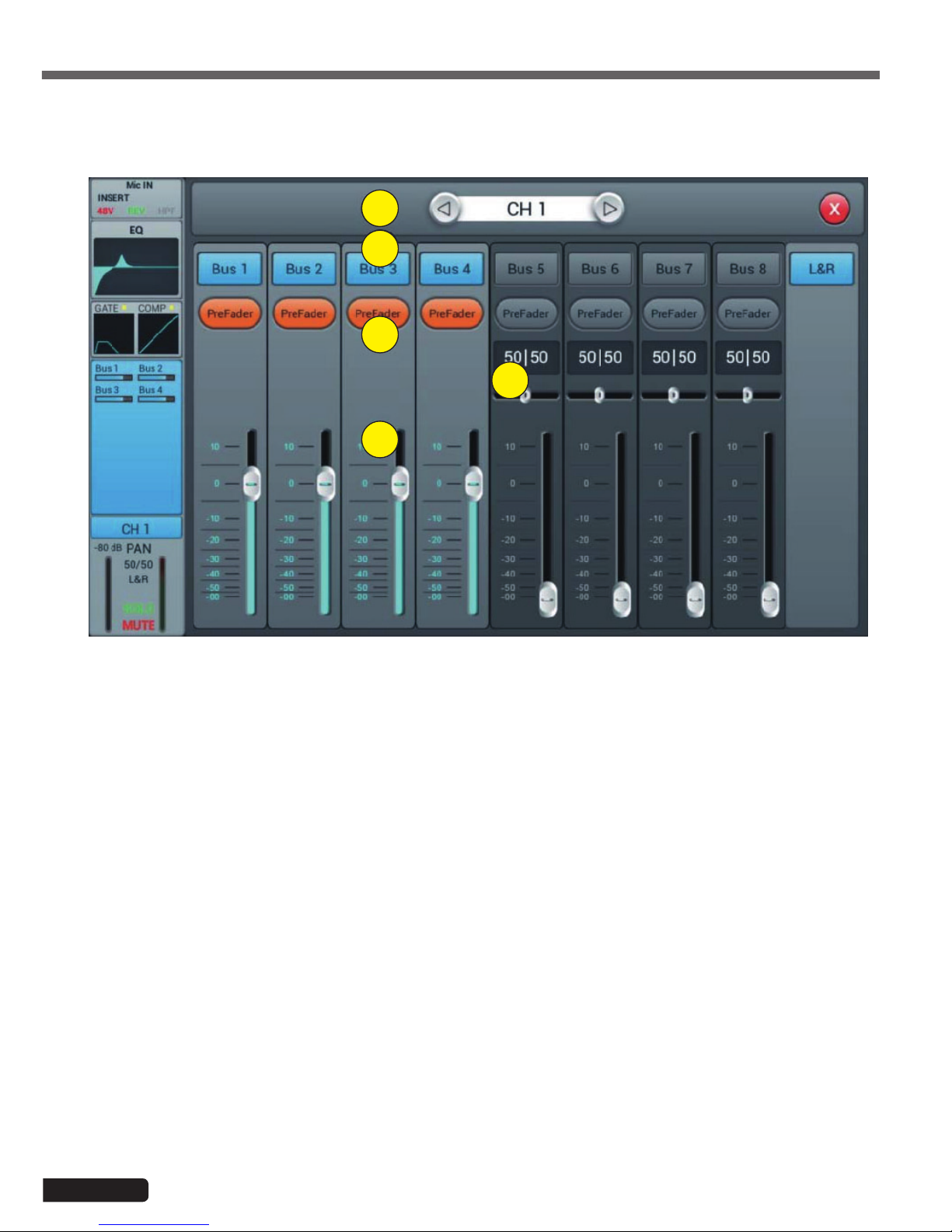
4-1-5 Bus Send sub-page
1
2
3
5
4
1- Channels selector
Allows you to switch from one channel to another while remaining on the same page.
2- Activate sending to buses
Press a bus button to send the active channel to it, press again to disable sending.
3 - Pre/PostFader
Switching between pre- and post-fader sent to a bus. The pre-fader does not include the gain value of the fader,
which can be useful for effect sends or monitoring. The default value is pre-fader.
4 - Pan
Controls panning in a stereo bus. The default value is 50|50 (middle). The PAN value can be changed by dragging
the slider or turning the adjustment dial. Press the numeric parameter control twice to return to the default value.
5 - Sending level to buses
Controls the level at which the signal is sent to the selected bus. This can be changed by moving the cursor on
the screen or by using the physical fader.
Each input channel can send signals to 4 mono buses (1-4), 2 stereo buses (5-8 including L/R master).
Page 13
LIVEtouch20 - 20 Channel Digital Mixing Console English
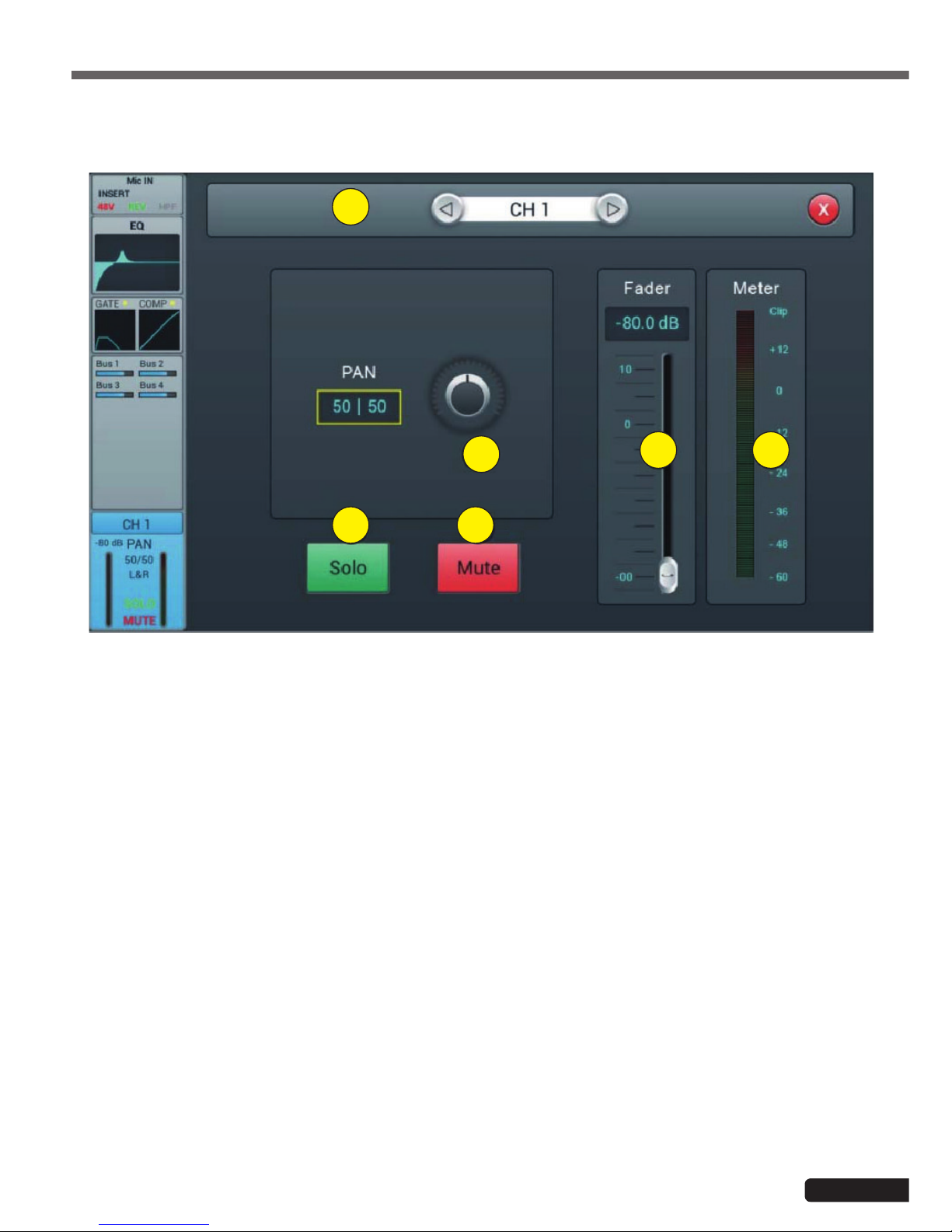
4-1-6 Output stage sub-page
1
2
3
5 6
4
1- Channels selector
Allows you to switch from one channel to another while remaining on the same page.
2- Panoramique
Controls the panning of the Master output. The default value is 50|50 (middle). The PAN value can be changed by
the encoder on the screen or by turning the control dial. Press the numerical control of the setting twice to reset
the setting to its default value.
3 - Solo
This is a copy of the SOLO hardware button on the front panel. Press to enable or disable the signal sent to the
solo monitor bus.
4 - Mute
Like Solo, it is a copy of the M button on the front panel. Press to mute or not the channel, which will mute or
mute all pre- and post-fader sends from the active channel to all buses, including the L/R Master.
5 - Fader
This is a copy of the physical fader of the selected channel. You can change the fader on the screen and the
physical fader will follow accordingly. Press the numerical control of the setting twice to reset the setting to its
default value.
6 - Vu-meter
This displays the pre-fader level of the signal, so regardless of the fader setting, the signal will be displayed here if
it is present.
Here you can set the pan and level of the Master as well as the Solo / Mute.

Page 14
LIVEtouch20 - 20 Channel Digital Mixing Console
English
4-1-7 Stereo inputs
Like the MIC channels, the two stereo inputs also include five modules: Input, equalizer, dynamic, bus sending and output.
A simple click on a module will bring up a subpage with other options. The subpages can be closed with the red "close"
button in the upper right corner.
1
2
3
4
5
1 - Input stage
Indicates the status of the phase, delay, high pass filter and effects.
2- EQ
Displays the current equalization and allows access to the settings.
3 - Dynamics
isplays compressor and gate status and provides access to settings.
4 - Buses sends
Displays the buses to which the channel is sent and provides access to the bus selection.
5 - Output stage
Displays channel name, pan setting, preview (SOLO), MUTE and channel level.
Page 15
LIVEtouch20 - 20 Channel Digital Mixing Console English
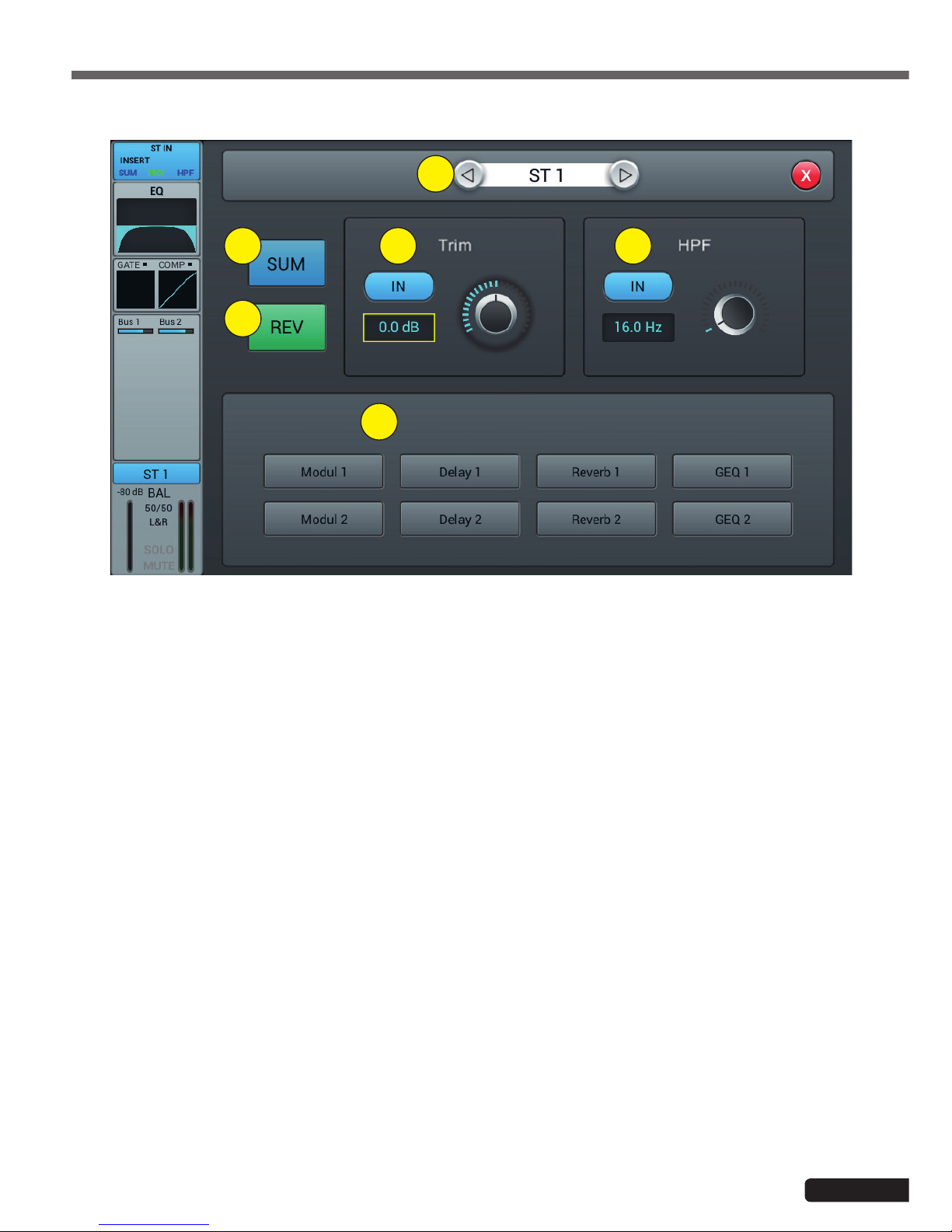
1
2
3
4 5
6
1- Channels selector
Allows you to switch from one channel to another while remaining on the same page.
2- SUM
Sum the left and right inputs, so that both sides of the stereo channel will contain the same signal (mono). This
can also be used to copy the signal to both channels if only one side of the stereo signal is connected.
3 - REV
The phase reverses the left side of your stereo signal. In combination with SUM, this can be useful to cancel the
stereo medium, which usually contains the voice of a recording, and create a simple karaoke effect.
4 - Trim
Allows digital amplification or attenuation of the input signal. Press IN to activate, the default value is disabled.
Adjust the trim on the touch screen or use the adjustment dial (fine adjustment can be activated by pressing and
holding the dial). Gain can be adjusted from -20 dB to 20 dB with 0dB as default.
5 - HPF
Enable the high pass filter, by default the high pass filter is disabled. The frequency can be set either via the set-
ting wheel or directly on the display. For fine adjustment, hold down the knob.
The frequency is adjustable from 16 Hz to 400 Hz, the default value is 16 Hz.
6 - Insert
Press one of the buttons on the effect module to insert it before equalizing the channels. Each effect module can
only be inserted in one place and the input channels allow only one effect module to be used. When a selected
module is used in another channel or bus, a pop-up window appears: "The module can only be used once and is
already used by xxx. Do you want to use the force module now? Yes / No".
To change the effect settings, press the SETUP button, then press FX and click a module to open a dialog box for
the effect.
4-1-8 Stereo inputs sub-page

Page 16
LIVEtouch20 - 20 Channel Digital Mixing Console
English
4-1-9 Parametric equalizer sub-page
This page is the same as for MIC channels. All settings will be applied to both channels of the stereo signal.
For ST1 and ST2, this page is the same as for MIC channels, with all settings applied to both channels of the stereo signal.
For S/PDIF and USB channels, there is no dynamic section.
For ST1 and ST2, this page is the same as for the MIC channel. For S/PDIF and USB Sending channels is limited to 5-8
stereo and Master LR buses. For mono buses, the sum on both sides of the stereo channel is actually sent to the bus. For
stereo and Master LR buses, a scale replaces the Panning : the center (50|50) of the BAL will send the left and right parts
of the stereo channel to the corresponding left and right parts of the Bus. Any other setting will attenuate one side of the
stereo channel, for example (100|0) only sends the left side of the stereo channel to the left side of the bus, the right side
being muted.
4-1-10 Dynamics sub-page
4-1-11 Bus Send sub-page

Page 17
LIVEtouch20 - 20 Channel Digital Mixing Console English
LIVEtouch20 allows mixing in a total of 8 output buses - 4 Mono (Bus 1~4), 2 Stereo (Bus 5~8 including Master L/R). In
fact, there is another stereo bus for monitoring via SOLO, which can be switched to pre or post-fader listen (PFL/AFL).
Press the BUS1-8 button on the front panel or drag to the right of the stereo channels on the screen to switch to BUS 1-8
view or by pressing the SEL button on the Master L/R to display Master view:
The left side of the page gives a complete overview of all the inputs and outputs of the console, the right side shows the
Master L/R output band, whose functionality exactly follows the 7-8 stereo buses.
Each output bus contains 4 modules - input stage, EQ, input source and output stage. With the exception of the input
source, which is in view only, all other modules will display a subpage if the corresponding part of the screen is clicked.
The subpages can be closed with the red "close" button in the upper right corner.
1
2
3
4
4-2 Output busses

Page 18
LIVEtouch20 - 20 Channel Digital Mixing Console
English
1 - Input stage
Displays the physical output assigned to each bus as well as the status of the effect inserts.
2- EQ
Displays a parametric equalizer graph representing the equalizer settings.
3 - Input source
Displays the status and send level of each channel as a bar graph. For clarity, only channels whose sending to a
given bus is enabled are displayed here.
4 - Output stage
Displays name, Pan/BAL value, Solo, Mute, delay, fader and level information. Double-click, for example Bus 1, to
change the name of the selected channel using a virtual keyboard that will appear on the screen.
Buses 1 to 4 are mono busses
4-2-1 Input stage sub-page
For mono buses 1-4, this page allows you to configure the send level, pan and type (Pre-/Post-Fader) for stereo buses
5-8. Since stereo buses cannot send to themselves, these buses (as well as mono buses) only enable/disable sending to
the Master L/R.
The bus text label indicates the physical output plug to which it is assigned. For example, OUT 1 is plug 1 on the back of
the console, etc. The assignment can be configured in the SETUP menu and then PATCH.
1
2
3
4
5
6
1- Channels selector
Allows you to switch from one channel to another while remaining on the same page.
2- Activate sending to busses
Press a bus button once, to send a channel signal to the bus, press again to turn it off.
3- Pre/Post Fader
Switching between pre- and post-fader sent to a bus. The pre-fader does not include the gain value of the fader,
which can be useful for effect sends or monitoring. The default value is pre-fader.

Page 19
LIVEtouch20 - 20 Channel Digital Mixing Console English
1
2
3
4 5
6 7
4- Pan
Controls the panoramic of the bus. The default value is 50|50 (middle). The PAN value can be changed by the
encoder on the screen or by turning the control dial. Press the numerical control of the setting twice to reset the
setting to its default value.
5 - Send level
Controls the level at which the signal is sent to the selected bus. This can be changed by moving the cursor on
the screen.
6 - Insert
Press a button on the effect module to insert it before the bus equalizers. Each effects module can be inserted
at a single point and while the input channels allow only one effects module to be inserted, all buses allow the
subsequent insertion of two effects modules. The order of the modules is determined by the selection order. When
a selected module is used in another channel or bus, a pop-up window appears: "The module can only be used
once and is already used by xxx. Do you want to use the force module now? Yes / No".
To change the effect settings, press the SETUP button, then press FX and click a module to open a dialog box for
the effect.
4-2-2 Parametric equalizer sub-page
4-2-2 Output stage sub-page
This page is the same as for MIC channels.
This page contains Delay, PAN, Solo, Mute, Fader Level Control and Signal Level Display. Bus5 to Bus8 and L&R bus
outputs are similar to Bus1 to Bus4.
1- Channels selector
Allows you to switch from one channel to another while remaining on the same page.
2 - Delay
Enables Delay, by default Delay is disabled. The time can be set either via the setting wheel or directly on the
display. For fine adjustment, hold down the knob.
The time range is 0 ms to 200 ms.

Page 20
LIVEtouch20 - 20 Channel Digital Mixing Console
English
3- Pan
Controls the panning of the Master output. The default value is 50|50 (middle). The PAN value can be changed by
the encoder on the screen or by turning the control dial. Press the numerical control of the setting twice to reset
the setting to its default value.
3 - Solo
Press to enable or disable the signal sent to the solo monitor bus.
4 - Mute
Press to mute or unmute the channel.
5 - Fader
This is a copy of the physical fader of the selected channel. You can change the fader on the screen and the
physical fader will follow accordingly. Press the numerical control of the setting twice to reset the setting to its
default value.
6 - Vu-meter
Channel signal level indicator, indicates the post-fader signal level.
Table of contents
Other audiophony Music Mixer manuals

audiophony
audiophony PREZONE444 User manual

audiophony
audiophony MX822 User manual

audiophony
audiophony MIXtouch8 User manual

audiophony
audiophony MX44 User manual

audiophony
audiophony PMX34 User manual

audiophony
audiophony MYA5D User manual

audiophony
audiophony DIGITAL-3 User manual

audiophony
audiophony PA PREZONE88 User manual

audiophony
audiophony GOA9C User manual

audiophony
audiophony PA DZONE88 User manual


