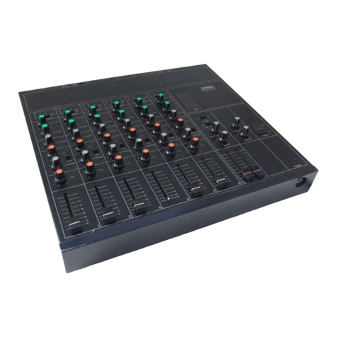
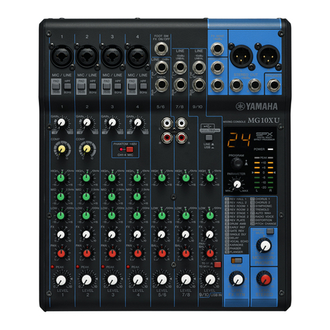
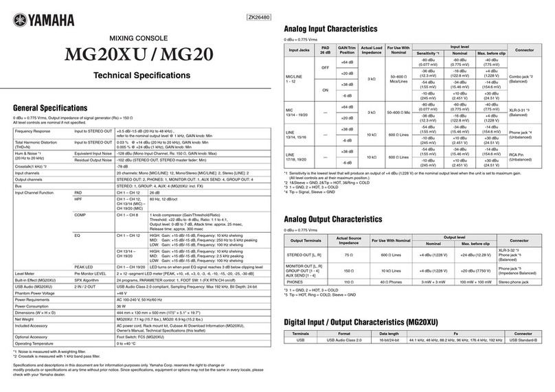
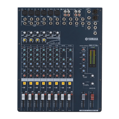
Yamaha PM-1000 User manual

FOUR
DOLLARS,

INTRODUCTION
The
PM-1000
is
a
4-bus
mixing
console
with
16,
24
or
32
input
channels.
Yamaha
engineers,
in
cooperation
with
soundmen,
mixers
and
performers,
designed
this
board
to
meet
with
widely
varied
demands
of
professional
sound
reinforcement,
as
well
as
studio
applications.
Modular
construction
and
all
solid
state
circuitry
assure
reliability
and
ease
of
maintenance.
To
enhance
its
appearance,
the
console
is
finished
with
durable,
black-anodized
aluminum
panels
and
housed
in
a
handsome
rosewood
cabinet
with
a
padded
armrest.
Carrying
handles
on
the
side
panels
and
a
padded
leatherette
cover
are
included
as
standard
equipment.
Every
console
is
delivered
complete
with
a
full
complement
of
modules,
and
ready
for
use.
Trans-
former
isolated
inputs
and
outputs,
plus
a
precision,
wide-range
input
sensitivity
selector
on
each
channel
help
simplify
installation
and
optimize
performance
with
virtually
any
type
of
audio
system. Further
convenience
is
afforded
by
the
many
XLR
connectors,
phone
jacks
and
stereo
phone
jacks
that
carry
all
input
and
output
signals.
The
PM-1000
is
built
to
exacting
standards.
It
is
light,
yet
rugged
enough
to
sustain
the
kind
of
punishment
that
often
occurs
in
portable
applications.
For
fixed
installations,
the
console
has
all
the
features
and
appearance
of
many
larger,
custom
boards.
Top
of
the
line
performance
at
an
economical
price
sets
the
PM-1000
in
a
class
by
itself.

————
INDEX
IDENTIFICATION
OF
PARTS
&
CONTROLS
SECTION
ONE
MAIN
COMPONENTS
&
SUB
ASSEMBLIES
2.050435
v8
pu
iid
es
Swe,
S
GP
Roe
E
Ba
Oe
Swe
De
1
INPUTMODUEE
*.
ске
дык
ена
а
hath
bie
dw
ea
bce
не
E
os
Bae
Ae
Pe
Қы
ТЕ
2
MASTER
S
MONITOR:
MODULE:
5
5524
кафе
delet
ad
dew
ac
a
hw
Sanna
лы
на
Soe
ek
та
3
HEADPHONE
&
ECHO
MODULE.
i3.
3.3
9
590b
ЖАЗ
Оғыз
аға
азы
а
Мола
OAS
4
TALKBACK
&
OSCILLATOR
MODULE
..
23
Tora
ke
RACE
E
eta
Ree
E
EE
ewe
EUR
EIER
UE
er
SR
DR
E
4
METER
PANEL
rcd
eA
DEO
А
a
cR
B
o
cg
n
ge
RES,
ор
WU
ULT
wee
Some
lana
eens
ac
d
o
oe
Sk
5
REAR
PANE
Е
2
usc
Mb
RM
ar
ee
x
Nee
ҰЛЫ
ee
v
ЫҚ
rave
dia
c
E
a
osos
wb
te
Or
5
SPECIFICATIONS
SECTION
TWO
GENERALE
SPEGIEICA
HONS
о
sundance
oe
haus
coe
vie
dre
apt
ao
ЕДЫ
&
ee
bee
dra
usd
pd
vat
E
1
DEFINITION
OF
TERMS:
UNBALANCED,
BALANCED
&
ҒІОАТІМС..........................
2
DEFINITION
OF
TERMS:
dB,
аву,
dBm
&
dB
ӨРІ........................................
2
INPUT
&
OUTPUT
CHARACTERISTICS
22522255555
Ұ
А
а
Me
SER
REOR
RUN
А
Ree
Ae
n
2
GENERAL
APPLICATIONS
SECTION
THREE
|
THE
ROLE
OF
AN
AUDIO
CONTROL-CONSOLE....—
zx
e
Vx
Ru
ACER
RU
Se
ee
a
XE
RR)
S
mis
1
Г
PLACEMENT
OF
EQUIPMENT-
оло
а
gas
eR
а
е
BE
oes
ЧА
V
S
EOS
ie
e
1
н
THE
DISTINCTION
BETWEEN
PROFESSIONAL
&
HI-FI
TYPE
EQUIPMENT.
.
.
...................
1
CHANNEL
INPUTS:
552599
ts
ee
2
Go
ced
ғұ
АН
RU
a
Rosen
i
ice
o
e
ioo
ue
aeq
IR
Ce
ORC
LORD
de
2
|
SUBMIXER
INPUTS...
ue
IU
UR
UN
ез
Елес
e
adum
ROAD
EIS
E
eed
ume
RR
Ure
BUS
2
PLAYBACK
INPUTS...
x
i
uod
e
cce
eign
oN
ew
Ai
era
OR
da
Rom
вр
Еа
OR
Den
Re
DAC DUE
Bua,
Б
на
sere
a
3
TALK
BAGS
INPUT
ss.
Cx
ftia
cue
Re
vt
pane
oak
wns
Ae
ees
Fed
IRURE
Аы
BUR
NAR
EA
A
E
3
MASTER
IN-&
MASTER
OUT
rrari
tk
reed
eee
oe
тіз
ыл en
RR
Vox
Fu
a
RÀ
eu
aq
dere
wu
RR
3
TIME
DELAY
EQUIPMENT
so
va
3
vem
NRI
DOR
OS
E
ETE
UR
ERE
BOR
RSCROAR
TA
РАН
PR
wine
RC
eee
4
GHAPHIO-EQUALIZATION
55
urs
аа
еа
S
UR
mE
CREE]
UU
f
Tp
Ы
ЕЖ
Балық
za
ie
RO
ОР
QUE
aaa’
4
COMPRESSION
RS
EIMITING:
zr
gn
e
a
ERE
RA
RES
VR
YE
New
P
Xx
RE
ARAS
4
INSTALLATION
SECTION
FOUR
PLACEMENT
OF
EQUIPMENT
ао
eR
кк
ақтала
Fx
wx
IDEE
ORM
eyes
CR
dua
1
POWER
MAINS:
22,2,
pcos
ае
ЕКЕ
а
IRE
WOALECTO.
Dae
ШЫН
SSR
ee
ee Be
1
THEORY
OF
GROUNDING.
xd
rado
Sees
cio
ewe
КЕ
Row
fer
eke
ЕНДЫ
NG
We
есін
eS
1
AUDIO
CONNECTORS
S
CABLE
TYPES
a
au
ч
Е
Dae
ae
c
ed
ee
Se
ea
2
CABLE
&
CONNECTOR
WIRING
CONFIGURATIONS
.....................................
6
PADS,
TRANSFORMERS
&
DIRECT
ВОХЕб...........................................
11
HOW
TO
USE
THE
CONSOLE
SECTION
FIVE
INPUPDMODULE
о
ae
cea
Pear.
ЫРА
aec
alode
ca
o
e
EUR
fa
oic
а
dod
pla
dear
qal
ur
Б
ОБА
1
MASTER
&
MONITOR
MODULE
3.5.0
cack
uh
nh
Rx
ER
he
ee
та
баста
а
RI
Ra
Kn
M
EE
5
HEADPHONE
&
ECHO
МОЮЦГЕ,....................................................
6
TALKBACK
&
OSCILLATOR
MODULE
оаа
xxm
dox»
Cw
лов
ЗЕК
RC
ROCA
re
lec
6
METER:
PANEL...
over
EE
SE
Ge
EUER
E
Eure
NUR
e
Eee
xl
See
SS
UK
e
EA
UR
EU
REN
RT
RR
PR
REEL
7
BLOCK
&
SCHEMATIC
DIAGRAMS
SECTION
SIX
BLOCK
DIAGRAM............
""""""---—-—————É——————À————
Ghee
1
SYSTEM
HEADROOM
„аас
аав
Ede
bie
ИНК
RUE
жалы
ыы
Sie
ERR
erate
Мы
БА
Serb
da
aes
2
POWER
SUPPLY
SCHEMATIC;
i22
vega
p
6 б
Re
ee
Roe
ROBUR
RUE ELS NUR
A A
EUR
o
ee
wae
2
INPUT
MODULE
SCHEMATIC.
roe
sanne
by
ehh
ho
sn
Rh
e
Rom
аа
а
а
EUROS
a
4%.
жа
жө,
3
FRAME
SCHEMATIC
а
Sw
а
ке
Бесін
GRAUE
ME
REOR
ee
SOE
BES
Rar
ho
ewes
3
MASTER
&
MONITOR
MODULE
...........
cles
elle
eee
Rh
mre
4
HEADPHONE
&
ECHO
МОООГЕ,....................................................
5
TALKBACK
&
OSCILLATOR
MODULE:
«2,23
dod
eae
SS
ee
PETES
REOR
CR
RR
өкі
EOE
жа
6
MAINTENANCE,
REPAIR
&
WARRANTY
SERVICE
SECTION
SEVEN
GENERAL
MAINTENANCE
МОТЕб5.............................................
ae
1
ACCESS
TO
THE
CONSOLE
INTERIOR
...............................................
1
POWER
SUPPLY
REMOVAL,
REPLACEMENT
&
220-240V
AC
СОМУЕНБІОМ.....................
1
INPUT,
MASTER,
HEADPHONE
&
TALKBACK
MODULE
REMOVAL
&
REPLACEMENT.............
2
WARRANTY
&
FACTORY
ASSISTANCE
..............................................
3
YAMAHA
PM-1000
PRODUCT
МУАВВАМТҰ............................................
3
TWENTY-FOUR
&
THIRTY-TWO
CHANNEL
CONSOLES
SECTION
EIGHT
GENERAL
DESCRIPTION:
255
he
a
Gene
ee
б
ee
eat
Д
ek
Ro
o
ter
RIT
Ne
e
ae
Gee
We
ee
ee
eee
D
1
REAR
ur
2

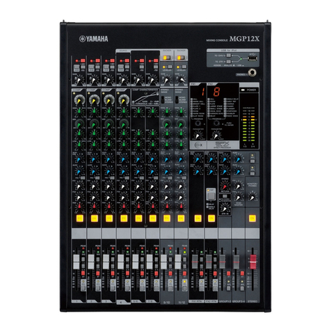
IDENTIFICATION
OF
PARTS
AND
CONTROLS
MAIN
COMPONENTS
&
SUB
ASSEMBLIES*
Input
(x
16)
Armrest
*Many
times
there
is
more
than
one
label
appropriate
to
a
console
control
or
function.
Depending
on
the
specific
application
or
the
industry
(recording
or
sound
reinforcement),
the
nomenclature
will
vary.
To
avoid
confusion
in
this
manual,
wherever
possible,
we
will
try
to
refer
to
the
nomenclature
actually
printed
on
the
Meter
Panel
Headphone
Jacks
Master
and
Monitor
Module
(x
4)
Headphone
and
Echo
Module
Talkback
and
Oscillator
Module
console.
Where
function
may
be
unclear,
an
alternate
term
may
be
printed
in
parentheses.
Some
examples
of
this
alternate
terminology
are:
Echo
(foldback
or
stage
monitor),
Monitor
(speaker
feed),
Line
Output
(program
output),
and
Sub
In
(auxiliary
input).

THE
INPUT
MODULE
A.
PHASE
SWITCH
Reverse
the
polarity
of
the
audio
signal
entering
the
input
module.
This
switch
eliminates
the
need
to
rewire
connectors
for
out-of-phase
audio
sources.
Sliding
the
switch
from
N
(normal)
to
R
(reverse)
interchanges
the
leads
joining
pins
2
and
3
of
the
XLR
connector
to
the
input
transformer's
primary
winding.
NOTE:
PM-1000
XLR
connectors
are
wired
according
to
DIN
Standards;
pin
2
high
and
pin
З
low.
Refer
to
the
Installation
Section
for
details.
Vorma/
phase
for
this
console
means
that
a
positive
voltage
applied
to
pin
2
at
the
input
causes
a
positive
voltage
to
appear
at
pin
2
of
the
XLR
outputs.
B.
OUTPUT
ASSIGN
(BUS
ASSIGN)
SWITCHES
Apply
audio
from
the
input
module
to
any
combination
of
the
four
program
mixing
buses.
Latching
switches
1,
2,
Запа
4
either
individually
or
in
any
combination
assign
post-equalizer
and
fader
audio
to
correspondingly
numbered
buses.
As
described
below,
adjusting
the
Pan
pot
to
either
side
of
center
alters
the
level
applied
to
the
four
program
mixing
buses.
C.
PAN POT
adjusts
the
relative
output
level
available
to
the
four
program
mixing
buses.
Panning
to
the
center
position
provides
equal
output
at
full
post-fader
ievel
to
all
four
Output
assign
switches.
In
other
words,
the
program
is
centered
in
four
buses.
Panning
to
the
left
gradually
removes
audio
from
the
feed
to
buses
2
and
4,
maintaining
full
output
to
buses
1
and
3.
Conversely,
panning
to
the
right
gradually
removes
the
output
from
buses
1
and
3,
maintaining
full
output
in
buses
2
and
4.
The
/eft
and
right
designations
are
arbitrary,
based
on
the
rotation
of
the
pan
pot;
they
refer
to
the
use
of
the
console's
line
outputs
for
driving
stereo
or
4-channel
recorders
and/or
loudspeaker
systems.
D.
ECHO
1
AND
ECHO
2
(ECHO
MIX
CONTROLS)
Adjust
the
module's
output
to
each
of
two
auxiliary
mixing
buses.
These
controls
apply
pre-fader,
post-equalizer
audio
to
the
correspondingly
numbered
echo
mixing
buses.
The
audio
on
these
buses
can
be
fed
to
external
reverbs,
echo
devices
or
tape
delay
units.
In
addition,
the
echo
outputs
are
ideally
suited
to
driving
performers'
cue
headphone
systems
or
stage
monitor
(foldback)
systems;
these
applications
require
external
power
amplifiers.
E.
EOUALIZER
Alters
the
frequency
response
of
the
input
module
in
order
to
create
a
tremendous
variety
of
tonal
characteristics.
The
Mid-Range
control
acts
on
any
of
three
presence
frequencies
(1kHz,
2kHz
or
4kHz),
as
determined
by
the
Mid-
Range
Select
Switch.
Mid-Range
provides
*
15dB
of
continuously
variable
peaking
equalization.
The
Bass
and
Treble
controls
provide
*
15dB
of
continuously
variable
shelving
equalization
at
100Hz
and
10kHz
respectively.
Centering
the
three
equalizer
controls
provides
flat
audio
response
by
defeating
all
equalization.
F.
HIGH
PASS
(LOW
CUT)
FILTER
Switch-actuated
12dB/octave
high
pass
filter.
The
filter
follows
the
equalizer,
affecting
the
output
to
the
cue,
echo
and
program
mixing
buses.
The
switch
has
three
positions:
OFF
bypasses
the
filter
entirely:
40
attenuates
audio
below
40Hz;
80
attenuates
audio
below
80Hz,
the
most
pronounced
filter
effect.
G.
INPUT
LEVEL
(INPUT
SENSITIVITY)
SWITCH
A
precision
4-stage
switch
that
varies
the
preamplifier
gain
and/or
attenuates
the
incoming
signal.
Input
Level
affects
all
outputs
from
the
module.
It
provides
optimum
results
with
virtually
any
input,
from
-60dB
to
+4dB.
When
correctly
adjusted,
Input
Level
permits
the
input
faders
and
echo
mix
controls
to
be
used
in
their
best
range
—
with
maximum
headroom
and
minimum
noise
characteristics.
The
switch
has
11
settings:
-60,
-50,
-44,
-38,
-32,
-26, -20,
-14,
-8,
-2
and
+4dB,
each
corresponding
to
a
nominal
input
level
(i.e.,
-GOdB
is
not
a
60dB
pad,
but
is
the
most
sensitive
characteristic
for
nominal
-60dB
inputs).
H.
CHANNEL
FADER
(INPUT
FADER)
A
straightline
control
which
provides
continuously
variable
adjustment
of
the
module's
output
to
the
program
mixing
buses,
completely
killing
the
signal
at
the
bottom
of
its
travel.
The
fader
has
no
effect
on
the
echo
or
cue
outputs
of
the
module.
1.
CUE
(PREVIEW/SOLO)
BUTTON)
Applies
audio
to
an
auxiliary
cue
mixing
bus
when
the
button
is
depressed.
The
cue
bus
is
fed
with
pre-fader,
post-equalizer
audio.
Since
the
cue
feed
is
unaffected
by
the
channel
fader
or
the
echo
mix
controls,
the
incoming
signal
may
be
previewed
prior
to
assigning
any
audio
to
the
program
mixing
or
echo
mixing
buses.
Cue
is
monitored
via
the
headphone
output.

MASTER
AND
MONITOR
MODULE
A.
DIRECT/PLAYBACK
(OUTPUT
SOURCE
SELECT)
SWITCH
Selects
the
audio
source
applied
to
the
master
module’s
input.
Direct
mode
derives
audio
from
the
program
mixing
bus
numbered
to
correspond
to
the
module
(or
from
any
source
plugged
into
the
Master
In
jack).
Playback
(PB)
mode
derives
audio
from
the
correspondingly
numbered
PB
іп
jack.
In
practice,
the
Direct/
PB
switch
selects
between
a
live
program
and
a
recorded
program
to
drive
the
console
output.
B.
MONITOR
MIX
(SPEAKER
MIX)
CONTROLS
These
rotary
level
controls,
labeled
CH-1
through
CH-4,
derive
audio
from
the
line
outputs
of
master
modules
1-4.
A
monaural
mixdown
of
the
line
out-
puts
is
obtained
by
adjusting
the
four
monitor
mix
controls.
This
mono
mix
is
brought
to
the
Monitor
Out
jack,
where
it
can
drive
a
power
amplifier
for
one
or
more
loudspeakers.
Since
there
are
four
master
modules,
each
with
an
identical
complement
of
four
monitor
mix
controls,
up
to
four
distinct
speaker
mixes
can
be
derived
from
the
original
four
line
outputs.
This
is
known
as
a
4x4
matrix
with
level
controls.
C.
MONITOR
MASTER
(SPEAKER
LEVEL)
CONTROL
Provides
overall
level
control
for
the
mono
mix
created
with
the
monitor
mix
controls
immediately
above
it.
When
the
four
monitor
out-
puts
are
driving
different
loudspeakers,
the
Monitor
Masters
adjust
the
balance
between
speaker
feeds.
This
4x4
matrix
arrangement
offers
far
more
flexi-
bility
for
speaker
feeding
than
would
be
available
if
the
speakers
were
driven
directly
from
the
four
line
outputs
(Line
A
or
Line
B).
D.
MASTER
FADER
(GROUP
MASTER)
Sets
the
overall
signal
level
applied
to
the
main
program
out-
puts
of
the
console,
Line
A
and
Line
B.
(Line
A
&
B
are
identical,
redundant
outputs,
each
consisting
of
four
connectors
that
derive
audio
from
the
Direct/
PB
switches.)
The
Master
fader
governs
the
corres-
pondingly
numbered
line
outputs,
whether
derived
from
the
program
mixing
bus
(in
Direct
mode)
or
the
Playback
input
(in
PB
mode).
Together,
the
four
faders
are
useful
for
balancing
the
levels
of
different
groups
of
inputs
that
have
been
assigned
to
the
four
mixing
buses;
in
this
capacity,
the
faders
are
Group
Master
controls.

ONIE4
HEADPHONE
AND
ECHO
MODULE
A.
ECHO
SEND
(FOLDBACK)
MASTER
CON-
TROLS
Provide
overall
level
control
for
echo
mixing
buses
1
and
2.
The
audio
mixes
established
with
the
echo
mix
controls
in
each
input
module
pass
through
the
Echo
Send
Masters,
and
drive
the
Echo
Out
jacks.
When
the
echo
outputs
are
connected
to
foldback
мед
(stage
monitor)
or
performers’
headphone
systems,
these
master
controls
determine
the
monitor
volume.
When
the
echo
outputs
are
connected
to
an
echo
or
reverb
device,
the
Master
controls
determine
the
level
of
the
delay
effect.
B.
HEADPHONE
MIX
PUSHBUTTONS
This
por-
tion
of
the
module
consists
of
two
rows
of
push-
buttons,
each
row
capable
of
selecting
any
combina-
tion
of
five
audio
sources.
The
left
and
right
rows
feed
audio
to
the
left
and
right
sides
of
the
head-
phone
output.
The
five
available
sources
are:
pro-
gram
mix
bus
1
through
program
mix
bus
4,
and
the
B
cue
bus.
When
more
than
one
pushbutton
per
row
is
latched,
the
selected
audio
sources
are
blended
in
equal
proportions.
C.
HEADPHONE
LEVEL
CONTROL
Simulta-
neously
adjusts
the
overall
volume
of
the
left
and
right
headphone
feeds.
This
stereo
output
is
available
at
two
stereo
phone
jacks.
The
jacks
are
wired
in
parallel
so
as
to
drive
one
or
two
pairs
of
stereo
headphones.
TALKBACK
AND
OSCILLATOR
MODULE
A.
OUTPUT
ASSIGN
SWITCHES
When
latched,
D
switches
1
through
4
apply
the
module’s
output
to
program
mixing
buses
1
through
4.
(16-channel
con-
soles
manufactured
after
February,
1976
(serial
no.
1542
&
up),
and
all
24
and
32-
channel
consoles
have
two
additional
buttons.
These
assign
the
module
output
to
Echo
Mix
buses
1
and/or
2.)
Depending
on
E
the
status
of
the
talkback
button,
the
output
will
be
either
a
vocal
signal
from
the
talkback
mic
input,
or
a
test
tone
from
the
built-in
oscillator.
B.
OSCILLATOR
FUNCTION
SWITCH
Turns
the
oscillator
OFF,
or
sets
it
for
constant
sine
wave
gen-
eration
at
1,000
Hz
or
at
7,000
Hz.
C.
TALKBACK
MICROPHONE
CONNECTOR
Accepts
any
low
impedance
microphone
for
use
with
the
talkback
circuitry.
D.
TALKBACK
LEVEL
CONTROL
Adjusts
the
talk-
back
microphone
preamplifier
gain.
This
control
affects
only
the
talkback
level,
not
the
oscillator.
E.
TALKBACK
BUTTON
Pressing
this
button
activates
the
talkback
mic.
If
the
oscillator
is
already
switched
on,
pressing
Talkback
interrupts
the
oscillator
and
sub-
stitutes
audio
from
the
talkback
preamplifier.
Headphone
&
Talkback
&
Echo
Module
Oscillator
Module

METER
PANEL
1
B
D
A.
MAIN
(PROGRAM
OUTPUT)
VU
METER
Four
illuminated
meters
that
provide
a
visual
indication
of
the
average
audio
output
level
from
Master
and
Monitor
modules
1
through
4.
Depending
on
the
setting
of
the
function
switch,
each
meter
displays
either
the
Master
(Line
Out)
or
Monitor
Out
level.
A
zero
VU
indication
is
equivalent
to
*4dBm
output
into
a
600-ohm
termination.
REAR
PANEL
f
A
CD
Ẹ
H
G
B
JIK
F
A.
POWER
FUSES
Protect
the
primary
(line)
and
secondary
(low
voltage)
portions
of
the
console’s
power
supply.
B.
POWER
CORD
CONNECTOR
Accepts
the
AC
power
cord
provided
with
the
console.
PM-1000
con-
soles
delivered
in
the
U.S.A.
and
in
Canada
are
equipped
with
grounded
(3-wire)
AC
cords
for
connection
to
50
or
60Hz,
110-120Vrms
AC
power
mains.
The
console
draws about
45
Watts,
or
0.5
Amps
(90
Watts
for
24/32
consoles).
C.
MASTER
OUT
&
MASTER
IN
Provide
a
patch
point
between
the
program
input
to
the
Master
and
Monitor
module
and
the
input
to
the
Direct/PB
switch.
The
jacks
are
wired
to
accept
standard
phone
plugs.
Their
nominal
operating
level
is
-20dB
(for
high
impedance
circuits).
D.
LINE-A-OUT
AND
LINE-B-OUT
JACKS
(PRO-
GRAM
MIX
OUT)
These
are
redundant
outputs.
Line
A
and
B
each
consist
of
four
jacks,
and
the
signal
is
derived
from
the
Master
Faders.
The
nominal
output
is
+4dBm
(for
600-ohm
termination),
and
the
con-
nectors
accept
XLR
type
3-pin
female
plugs.
*
E.
MONITOR
OUT
(SPEAKER
FEED)
JACKS
Carry
the
console
output
from
the
Monitor
Mix
(Speaker
Matrix)
section.
Each
Mon
Out
jack,
1
through
4,
carries
audio
from
the
correspondingly
numbered
Monitor
Master
control.
The
outputs
are
nominal
+4dBm
(for
600-ohm
termination),
and
the
connectors
accept
XLR
type
3-pin
female
plugs.”
F.
CHANNEL
INPUT
JACKS
Numbered
1
through
16,
the
Input
jacks
accept
audio
from
any
low
impedance,
balanced
or
floating
audio
source
from
-60dB
to
+4dB
nominal
level.
The
inputs
are
balanced
and
trans-
former-isolated,
but
auxiliary
matching
transformers
tSee
Section
8
for
24/32
Consoles.
B.
METER
FUNCTION
SWITCH
Two-position
slide
switch
allows
use
of
the
associated
VU
meter
for
monitoring
either
of
two
console
outputs,
Master
(Line)
or
Monitor.
The
Master
indication
is
derived
from
the
Line
Out
A
jack,
and
the
Monitor
reading
is
derived
from
the
Monitor
Out
jack
that
corresponds
in
number
to
the
VU
meter.
C.
ECHO
OUTPUT
VU
METER
Two
illuminated
VU
meters
provide
a
visual
indication
of
the
signal
level
at
the
Echo
1
and
Echo
2
outputs.
When
driving
monitor
(foldback)
systems
from
the
echo
outputs,
these
meters
indicate
the
stage
monitor
level.
A
zero
VU
indication
is
equivalent
to
a
+4dBm
output
into
a
600-ohm
termination.
D.
MAIN
POWER
(AC
ON/OFF)
SWITCH
Pushbutton
alternately
switches
the
AC
power
on
and
off.
No
audio
passes
through
the
console
when
power
is
off.
are
recommended
for
unbalanced,
high-impedance
inputs.
The
connectors
accept
XLR
type
3-pin
male
plugs.
G.
SUBMIXER
INPUT
JACKS
Numbered
1
through
4,
these
jacks
accept
audio
from
a
low
impedance,
low
level
source,
such
as
the
Yamaha
PM-400B
mixer.
The
Sub
In
jacks
are
designed
for
nominal
-20dB
levels,
and
accept
XLR
type
3-pin
male
plugs."
Audio
from
Sub
In
is
applied
to
the
program
bus
ahead
of
the
Master
Faders,
thus
the
Master
Faders
control
the
Sub
In
level.
H.
PLAYBACK
INPUT
JACKS
Numbered
1
through
4,
the
PB
In
jacks
accept
audio
from
a
low
impedance,
low
level
tape
machine
output.
This
audio
is
applied
to
the
PB
side
of
the
Direct/PB
switch
in
the
correspondingly
numbered
Master
and
Monitor
module.
The
PB
In
jacks
are
designed
for
-20dB
levels
and
accept
XLR
type
3-
pin
male
plugs.
*
I.
ECHO
OUTPUT
(FOLDBACK
OUT)
JACKS
Carry
the
console
output
from
Echo
Send
1
&
2
Masters.
The
Echo
Out
jacks
are
transformer-isolated,
nominal
*4dBm
(for
600-ohm
termination),
and
they
accept
XLR
type
3-pin
female
plugs."
As
discussed
previously,
these
jacks
may
be
used
to
drive
foldback
(stage
monitor)
amplifiers
or
performers'
headphone
amplifiers.
J.
TALKBACK
OUTPUT
JACK
Carries
the
output
of
the
Talkback
&
Oscillator
module,
even
if
the
module's
bus
assign
switches
are
not
latched.
The
TB
Out
jack
can
be
connected
to
a
power
amplifier,
directly
to
head-
phones,
or
to
any
point
where
the
oscillator
or
talkback
signal
is
needed.
For
calibrated
operation
with
optimum
fidelity,
TB
Out
delivers
+4dBm
into
a
600-ohm
ter-
mination.
The
connector
accepts
an
XLR
type
3-pin
female
plug.
*
K.
PHANTOM
POWER
SWITCH
Connects
the
48Vdc
phantom
power
supply
to
the
center
tap
of
all
input
transformer
primary
windings.
24/32
consoles
have
switches
for
each
input.
Recommended
procedure
is
to
turn
off
the
phantom
power
whenever
condenser
microphones
are
not
used;
however,
the
“phantom”
switch
may
be
left
on
without
damaging
most
standard
microphones,
line
inputs,
or
the
phantom
supply.
*Refer
to
the
Installation
Section
of
this
Manual
for
information
regarding
the
polarity
of
all
ХІ
В
connectors.

SPECIFICATIONS
SECTION
TW
GENERAL
SP
ECIFICATIONS
see
Section
8
for
those
specifications
which
differ
on
24
and
32
channel
consoles.
Frequency
Response
Total
Harmonic
Distortion
Hum
and
Noise*
(20Hz
-
20kHz)
Maximum
Voltage
Gain
(Input
Selectors
at
-60dB,
where
applicable)
Equalization
High
Pass
Filter
Oscillator
Talkback
Inputs
to
Console
Mixing
Buses
Console
Outputs
Crosstalk
VU
Meters
(0
VU=+4dBm)
Phantom
Power
Power
Supply
Finish
Dimensions
Weight
Accessories
Warranty
+0,
-4dB,
20Hz
-
20kHz;
+0.5dB,
50Hz
-
15kHz.
Less
than
0.25%
©
+10dB,
20Hz
-
20kHz;
Less
than
0.596
@
+20dB,
70Hz
-
15kHz.
-124dBm
Equivalent
Input
Noise
(E.I.N.).
-69dB
(73dB
S/N)
Line
Out
A
&
B:
Master
Fader
at
nominal
level
and
all
Input
Faders
down.
-60dB
(64dB
S/N)
Line
Out
A &
B:
Master
Fader
and
one
Input
Fader
at
nominal
level.
-63dB
(67dB
S/N)
Echo
Out:
Master
Send
at
nominal
level
and
all
Echo
Mix
Controls
down.
-54dB
(58dB
S/N)
Echo
Out:
Master
Send
and
one
Echo
Mix
Control
at
nominal
level.
PROGRAM
—
74*24B
from
Channel
In
to
Line
Out
A
&
B.
48*
2dB
from
Channel
In
to
Master
Out.
MONITOR
—
74+
2а4В
from
Channel
іп
to
Monitor
Out.
ECHO
—
74+
2dB
from
Channel
In
to
Echo
Out.
SUB
IN
—
30+
2dB
from
Sub
In
to
Line
Out
A
&
B.
PB
IN
—
30*
2dB
from
PB
In
to
Line
Out
A
&
B.
MASTER
—
32+
2dB
from
Master
In
to
Line
Out
A
&
B.
BASS
—
+15dB
@
100Hz,
shelving.
MID-RANGE
—
+15dB
@
1kHz,
2kHz
or
4kHz;
peaking.
TREBLE
—
+15dB
©
10kHz,
shelving.
12dB
per
octave
roll-off
below
40Hz
or
8ОН2.
1kHz
or
7kHz
sine
wave,
+4dBm
@
<1.0%
THD.
Microphone
input
jack,
preamp,
level
control,
and
push-to-talk
switch;
to
pgm.
buses
and/or
direct
out.
16
x
Channel
Inputs
(microphone
and
line
sources).
4
x
Sub
In
(Submixer
input).
4x
Master
In
(Hi-Fi
auxiliary
program
input).
4
x
PB
In
(Playback
input).
1
x
Talkback
Mic
In.
4
x
Main
Program
(Line
Out).
4
x
Monitor
(Speaker
feed).
2
x
Echo
(Foldback/stage
monitor).
1
x
Cue
(Preview).
8
x
Line
(4
Line
A,
4
Line
B).
4
x
Monitor
(Speaker
feed).
4
x
Master
(Hi-Fi
auxiliary
program
output).
2
x
Echo
(Foldback/stage
monitor).
1
x
Talkback
(Talkback
mic
or
oscillator
out).
2
x
Stereo
Headphone
(Console
operator's
monitor).
-60dB
at
1,000Hz,
adjacent
inputs,
-50dB
at
1,000Hz,
input
to
output.
4
x
large,
illuminated
meters;
switchable
for
Master
(Line
Out)
or
Monitor
(Monitor
Out).
2
x
small,
illuminated
meters;
Echo
(Foldback)
Out.
48Vdc
applied
to
balanced
channel
input
transformers
for
powering
condenser
microphones.
May
be
turned
On
or
Off
with
rear-panel
switch.
Self-contained
module
inside
console,
fused
and
fully
regulated.
Requires
110-120
VAC,
50-60Hz,
45
Watts.
May
be
modified
for
220-240V
AC
operation.
Black
anodized
aluminum
panels,
padded
armrest,
rosewood
veneer
cabinet.
34%"
(87.2cm)
wide
X
34%"
(87.5cm)
deep
X
11”
(27.7ст)
high.
110
pounds
(50kg).
Integral
carrying
handles
and
removable
leatherette
cover
are
included
with
console.
One
year,
parts
and
labor.
*Measured
with
6dB/octave
filter
@
12.47kHz:
equivalent
to
a
20kHz
filter
with
infinite
dB/octave
attenuation.

ТО
2
DEFINITION
OF
TERMS:
UNBALANCED,
BALANCED
&
FLOATING
Unbalanced,
balanced
and
floating
circuits
may
all
be
transformer-isolated.
The
distinction
between
them
lies
in
the
way
the
circuits
are
referenced
to
ground
(audio
common).
A
FLOATING
circuit
has
no
ground
refer-
ence,
as
illustrated
by
the
primary
of
the
РМ-1000%
Sub
In,
PB
In,
and
Talkback
Mic
input
transformers
and
by
the
secondary
windings
of
the
Line
Out,
Monitor
Out,
Echo
Out
and
Talkback
Out
transformers.
The
PM-1000’s
input
channel
transformer
primaries
are
BALANCED
by
virtue
of
their
center
taps.
A
bal-
anced
circuit
requires
either
a
center
tapped
transformer,
or
resistors
from
each
side
of
the
transformer
to
ground;
either
condition
places
both
sides
of
the
transformer
at
an
equal
difference
from
ground
potential.
іп
other
words,
the
transformer
is
balanced
with
respect
ground.
Any
circuit
which
causes
one
side
of
an
input
or
out-
put
to
be
grounded
is
considered
an
unbalanced
circuit,
unbalanced
in
that
both
sides
of
the
circuit
are
at
dif-
ferent
potentials
with
respect
to
ground.
Most
non-
transformer
connections,
including
the
PM-1000's
Master
In
and
Master
Out
jacks,
are
unbalanced
(there
are
exceptions,
but
they
are
rare).
Typical
unbalanced
audio
sources
are:
direct
feeds
from
electric
instruments,
from
power
amplifiers,
and
from
high
fidelity
tape
machines.
In
order
to
obtain
best
results
when
using
these
devices
with
the
PM-1000's
channel
inputs,
a
matching
transformer
should
be
inserted
at
the
remote
device.
The
transformer
prevents
the
console's
input
transformer
from
becoming
un-
balanced,
which
may
induce
noise
and
crosstalk.
Also,
the
matching
transformer
provides
the
best
impedance
match
for
high
impedance
sources.
Typical
floating
sources
(which
maintain
a
balanced
condition
in
the
PM-1000
channel
inputs)
are:
micro-
phones,
transformer-isolated
submixers,
and
virtually
any
transformer-isolated
output
from
auxiliary
pro-
fessional
equipment.
DEFINITION
OF
TERMS:
dB,
dBV,
dBm
and
dB
SPL
The
term
dB,
which
means
decibel
(1/10th
of
a
Bel)
expresses
a
ratio.
More
precisely,
dB
is
10
times
the
logarithm
of
a
power
ratio
and
20
times
the
logarithm
of
a
voltage
or
sound
pressure
ratio.
dBV
expresses
a
voltage
ratio.
It
is
not
directly
related
to
current
or
circuit
impedance.
The
0
dBV
refer-
ence
is
usually
1V
rms.
dBm
expresses
a
power
ratio.
It
is
related
to
the
voltage
or
current
across
a
low
impedance.
The
0
dBm
reference
is
0.775Vrms
in
a
600-ohm
circuit,
which
is
equal
to
1
milliwatt
at
600
ohms.
dB
SPL
expresses
an
acoustic
pressure
(not
power)
ratio.
The
O
dB
SPL
reference
is
approximately
the
threshold
of
human
hearing
at
1kHz,
which
is
equal
to
0.0002
dynes/cm2.
dB
expresses
the
difference
between
two
levels
(power,
voltage
etc.)
and
is
a
relative
term.
The
difference
between
+10dBm
and
+4dBm
is
6dB.
The
difference
between
-20dBV
and
-10dBV
is
10dB.
dBV
and
dBm
are
not
numerically
equal
when
dealing
with
600-ohm
circuits,
although
they
are
close
(OdBV
is
2.2dBm
at
600
ohms).
As
the
impedance
is
changed
to
other
than
600-ohms
(given
a
constant
voltage),
the
value
of
dBV
remains
constant
while
the
value
of
dBm
changes.
Consider
а
+4dBm
output
terminated
by
600
ohms;
the
voltage
level
is
+1.8dBV.
This
circuit
has
a
voltage
drop
of
1.23V
rms,
and
a
power
dissipation
of
2.5
milliwatts.
If
the
voltage
now
remains
constant,
but
the
termination
is
changed
to
1200-ohms,
the
power
dissipation
drops
to
1.23mW,
+1dBm.
Since
the
power
dissipation
in
high
impedance
cir-
cuitry
is
negligible,
"dBV"'
is
sometimes
used
to
express
signal
levels
in
high
impedance
lines.
“dBm”
is
com-
monly
used
to
express
signal
(power)
levels
in
low
impedance
lines,
roughly
between
4
and
1200-ohms.
To
avoid
confusion,
we
use
the
term
"dB"
to
represent
a
specific
voltage,
whether
it
is
applied
to
a
low
or
a
high
impedance.
OdB
is
referenced
to
0.775V,
and
OdBm
is
referenced
to
1mW
(0.775V
driving
a
600-ohm
termina-
tion).
For
example,
when
12.3V
is
fed
to
a
high
impedance,
the
level
is
designated
“+24dB.”
When
+24
dB
(12.3
volts)
drives
a
600-ohm
termination,
the
level
is
designated
"*24dBm."
An
increase
of
3dB
is
equivalent
to
2
X
the
power.
An
increase
of
10dB
is
equivalent
to
10
X
the
power.
A
decrease
of
3dB
is
equivalent
to
1/2
the
power.
A
decrease
of
10dB
is
equivalent
to
1/10
the
power.
An
increase
of
6dB
is
equivalent
to
2
X
the
voltage
or
SPL.
An
increase
of
20dB
is
equivalent
to
10
X
the
voltage
or
SPL.
A
decrease
of
6dB
is
equivalent
to
1/2
the
voltage
or
SPL.
A
decrease
of
20dB
is
equivalent
to
1/10
the
voltage
or
SPL.
The
open
circuit
voltage
output
of
a
low-Z
micro-
phone
(in
dBV),
given
a
94dB
SPL
sound
field,
is
approx-
imately
equal
to
the
microphone's
rated
EIA
sensitivity.
If
the
sound
level
at
the
mic
is
higher
than
94dB
SPL,
add
the
difference
to
the
EIA
rating,
and
if
the
level
is
below
94dB
SPL,
subtract
the
difference
from
the
EIA
rating.
Thus,
a
mic
rated
at
-bOdB
EIA
sensitivity,
placed
in
a
104dB
SPL
environment,
will
yield
about
-40dBV
(-37.8dB,
or
10mV)
output.
INPUT
&
OUTPUT
CHARACTERISTICS
INPUT
SPECIFICATIONS
IMPEDANCE
Connection
Actual
Nominal
Source
SENSITIVITY*
INPUT
LEVEL
Connector
(At
Max.
Gain)
Nominal*
Max.before
Clip.
In
Console
Inputs
(1-16)
PB
&
Sub
In
(1-4)
Master
In
(1-4)
1700
О,
balanced
2300
Q,
floating
9000
О,
unbal.
150
О
Mics
&
600
N
Lines
600
О
Lines
&
Instruments
5k
О
Lines
&
Instruments
0.25mV
(-70dB)
0.8mV
(-60dB)
12.3V
(*24dB)
XLR-3-31
40mV
(-26dB)
80mV
(-20dB)
3.2V
(*12dB)
XLR-3-31
З1тУ
(-28dB)
62mV
(-22dB)
12.3V
(+24dB)
Phone
Jack
Talkback
Mic
2300
Q,
floating
150
Q
Mics
8mV
(-40dB)
2.5mV
(-50dB)
1.23V
(*4dB)
XL
R-3-31
OUTPUT
SPECIFICATIONS
IMPEDANCE
POWER
OUTPUT
LEVEL
Connector
Connection
Actual
Nominal
Load
Nominal
Max.
before
Clipping
In
Console
m
Line
A
(1-4)
Line
B
(1-4)
Monitor
(1-4)
100
О,
floating
600
0.
1.23V
(+4dBm)
10.8У
(ғ2212аВт)
XLR-3-32
Echol
&2
Talkback
Master
Out
(1-4)
200
О,
unbal.
5,000
Q
62mV
(-22dB)
2.1V
(+9dB)
Phone
Jack
Headphones
3.2
О,
unbal.
8
О
or
greater
80mV
(-20dB)
1.23V
(*4dB)
Stereo
Phone
Jack
(x
2)
*
This
is
the
level
required
to
produce
an
output
of
*4dBm
(1.23V).

SECTION
THREE
1
GENERAL
APPLICATIONS
THE
ROLE
OF
AN
AUDIO
CONTROL
CONSOLE
The
mixing
console
is
the
heart
of
a
sound
system.
The
console
receives
all
microphone
and
recorded
sources,
amplifies
the
sound,
and
processes
it.
Auxiliary
devices
(compressors,
limiters,
reverbs,
tape
machines
and
amplifiers)
are
connected
to
the
sound
system
via
the
console.
Within
the
console,
some
sources
are
com-
bined,
and
others
are
assigned
to
more
than
one
output.
Level
balancing,
panning,
filtering
and
equalization
are
all
integral
functions
of
the
console.
Ultimately
the
console
feeds
tape
machines,
and/or
it
drives
power
amplifiers
that
in
turn
drive
loudspeakers.
Often
there
are
more
than
one
set
of
loudspeakers,
each
with
varying
program
feeds.
The
PM-1000
is
designed
to
satisfy
a
wide
spectrum
of
audio
control
requirements.
It
has
ample
flexibility
to
serve
as
a
recording
studio
console,
and
it
will
deliver
excellent
results
in
the
largest
of
sound
reinforcement
applications.
Ideal
for
reinforcement
in
large
clubs,
theatres,
auditoriums,
concert
halls
and
amphitheatres,
the
PM-1000
is
unsurpassed
for
its
versatility,
portability
and
economy.
PLACEMENT
OF
EQUIPMENT
The
object
of
a
sound
system
is
to
deliver
an
amplified
version
of
some
original
audio
source
to
the
audience.
Due
to
the
significant
and
varied
effects
of
room
acoustics,
the
sound
in
different
environments
can
never
be
identical.
However,
a
skilled
operator
using
sophisticated
equipment
can
critically
evaluate
the
sound
quality
and
modify
the
audio
to
obtain
a
reasonably
good
approximation
of
the
“ideal”
sound.
The
console
operator
must
have
continuous,
accurate
information.
He
must
know
what
the
audience
is
hearing.
Because
performances
tend
to
be
dynamic,
changing
constantly,
the
most
effective
means
to
guide
the
opera-
tor
is
to
place
the
console
in
the
midst
of
the
audience.
A
preferred
location
is
centered
left-to-right,
and
slightly
more
than
half
way
to
the
rear
of
the
audience.
In
this
position,
the
direct
sound
from
the
stage
and
the
colora-
tion
from
room
acoustics
jointly
affect
decisions
at
the
console.
For
convenience,
tape
machines
and
auxiliary
signal
processing
gear
are
usually
placed
immediately
adjacent
to
the
console.
The
only
electronics
that
are
remotely
located
are
the
microphones
and
the
power
amplifiers
which
drive
the
loudspeakers.
*
*Power
amplifiers
should
be
mounted
as
close
as
is
practical
to
the
loudspeaker(s)
they
drive.
By
keeping
the
amplifier-to-
loudspeaker
distance
as
short
as
possible,
and
by
using
a
suffi-
ciently
large
wire
gauge,
large
power
losses
due
to
dissipation
in
the
transmission
cable
are
avoided.
The
practice
of
locating
power
amplifiers
remotely
from
the
console
is
suitable
for
stage
monitor
(foldback),
main
reinforcement
and
intercom
loud-
speakers,
as
well
as
for
auxiliary
headphone
drive
amps.
If
the
console
cannot
be
placed
in
the
middle
of
the
audience,
an
alternate
position
is
at
the
rear
of
the
listening
area.
In
this
location,
the
console
operator
needs
an
assistant
who
will
stay
in
the
middle
of
the
audience.
From
there,
the
assistant
can
keep
the
console
operator
abreast
of
the
sound
quality,
and
can
suggest
necessary
adjustments.
In
recording
studio
applications,
the
PM-1000
should
be
placed
in
a
control
booth
that
is
acoustically
isolated
from
the
studio.
However,
visual
contact,
via
sound-trapped
windows
or
closed
circuit
TV,
should
be
maintained.
Auxiliary
equipment
should
be
placed
near
the
console,
in
the
control
booth.
Due
to
the
relatively
short
distance
between
the
control
room
and
the
studio,
all
power
amplifiers
can
be
located
in
the
control
booth
or
in
an
adjacent
room.
Echo
chambers
and
echo
devices
should
be
isolated
from
loud
monitoring
environments
to
reduce
the
likelihood
of
acoustic
feedback
or
leakage.
(Consult
Section
Four
of
this
manual
for
some
illustrated
examples
of
typical
console
set-ups.)
THE
DISTINCTION
BETWEEN
PROFESSIONAL
AND
HI-FI
TYPE
EQUIPMENT
іп
virtually
any
application,
a
variety
of
auxiliary
equipment
will
be
connected
to
the
PM-1000.
This
equipment
includes:
tape
machines,
compressors,
graphic
equalizers,
echo
devices,
reverb
units,
phasers,
and
just
about
any
audio
electronics
imaginable.
Regard-
less
of
the
function
of
auxiliary
equipment,
it
wili
un-
doubtedly
fall
into
one
of
two
general
categories,
professional
type
or
hi-fi
type
(semi-pro).
The
distinction
between
professional
and
hi-fi
equip-
ment
is
very
important
because
it
affects
the
way
this
equipment
will
be
used
with
the
PM-1000.
Brand
name,
size,
panel
colors,
durability,
and
subtieties
in
function
are
not
the
significant
differences.
What
matters
is
that
professional
equipment
and
hi-fi
equipment
usually
operate
at
different
input
and
output
levels,
and
require
different
source
and
load
impedances
to
function
correctly.
The
PM-1000
is
designed
to
function
at
its
peak
with
professional
equipment,
but
it
will
yield
excellent
results
with
hi-fi
type
equipment
so
long
as
certain
precautions
are
observed.
These
precautions
are
outlined
in
the
Installation
section
of
the
manual,
but
the
following
paragraphs
are
intended
to
explain
how
the
specific
requirements
of
professional
and
hi-fi
equipment
differ.
IMPEDANCE
Professional
equipment
is
generally
designed
to
be
driven
from
a
600-ohm
source,
and
its
output
will
drive
600-ohm
or
higher
impedance
loads.
Often,
professional
input
and
output
circuits
are
transformer
isolated
(balanced
or
floating);
such
circuits
utilize
dual-con-
ductor
shielded
cables,
with
3-pin
XL
type
audio
con-
nectors
(or
Tip/Ring/Sleeve
type).
Hi-fi
equipment
is
designed
to
be
driven
from
a
5,000-ohm
or
lower
impedance
source,
and
its
output
will
drive
10,000-ohm
or
higher
impedance
loads.
Hi-fi
input
and
output
circuits
are
usually
unbalanced;
such
circuits
utilize
single-conductor
shielded
cables
with
2-conductor
audio
connectors
(standard
phone
type
or
RCA
pin
type).

TAREE
2
The
nature
of
balanced,
floating
and
unbalanced
circuitry
is
detailed
in
the
Specifications
section
of
this
manual.
For
the
purpose
of
this
discussion,
the
most
significant
point
is
that
an
unbalanced
circuit
is
some-
what
more
susceptible
to
hum
and
noise,
especially
if
there
is
any
irregularity
in
the
grounding
system.
It
should
be
noted
that
whether
a
circuit
is
unbalanced,
balanced
or
floating
has
no
direct
correlation
with
its
impedance.
Low
impedance
and
high
impedance
are
relative
terms.
A-150
ohm
microphone
is
considered
low
impedance,
whereas
a
2,000-ohm
mic
is
considered
high
impedance.
A
600-ohm
line
is
considered
low
impedance,
whereas
5,000-ohm,
50,000-ohm,
or
100,000-ohm
lines
are
all
considered
high
impedance.
For
audio
transmission
over
long
distances,
low
impedance
lines
provide
the
best
results.
High
impedance
lines
attenuate
the
higher
frequencies,
however
in
short
cable
runs,
under
10
feet,
there
is
virtually
no
difference
between
the
results
obtained
with
low
and
high
imped-
ance
lines.
Also,
provided
the
grounding
is
correct,
there
is
little
difference
between
unbalanced
and
balanced
or
floating
circuitry.
In
any
case,
the
specific
requirements
of
the
PM-1000’s
input
and
output
circuits
should
be
considered
in
setting
up
the
system.
OPERATING
LEVELS
Professional
line
level
is
nominally
between
OdBm
and
*4dBm;
that
is,
the
average
program
level
is
approxi-
mately
.775Vrms
to
1.23Vrms
terminated
by
a
600-ohm
line.
The
peak
level
may
extend
up
to
about
*24dBm
or
higher
(12.3Vrms).
The
high
level
input
(not
mic
input)
of
professional
audio
equipment
is
designed
to
accept
levels
in
this
power
range
without
overdrive
(clipping
distortion);
most
professional
equip-
ment
can
be
driven
to
full
output
by
nominal
+4dBm
input
levels.
Hi-fi
type
equipment
operates
at
considerably
lower
levels
than
professional
equipment,
approximately
-16dB
nominal.
This
is
equal
to
about
120mV
across
a
10,000-ohm
or
greater
(high
impedance)
line.
Peak
program
levels
may
reach
or
slightly
exceed
+4dB,
1.23V
—
across
a
high
impedance
line.
Thus,
hi-fi
equip-
ment
is
usually
not
capable
of
driving
professional
equipment
to
its
full
output,
or
at
least
not
before
the
hi-fi
output
reaches
a
high
level
of
distortion.
More-
over,
when
the
output
of
hi-fi
equipment,
which
is
meant
to
be
terminated
in
a
high
impedance,
is
con-
nected
directly
to
professional
equipment,
the
low
impedance
acts
as
a
partial
short-circuit.
This
serves
to
overload
the
hi-fi
output.
The
PM-1000's
channel
inputs
are
correctly
matched
to
professional
equipment;
they
will
not
overload
low
impedance
microphones
and
lines.
But
the
same
inputs
can
overload
some
hi-fi
equipment.
To
prevent
possible
overload,
and
to
obtain
the
best
frequency
response
with
hi-fi
equipment,
a
matching
transformer
may
be
installed.
This
converts
a
high
impedance
to
a
low
impedance.
Approximately
10dB
to
20dB
of
voltage
level
is
lost
in
the
transformer,
but
this
level
can
be
recovered
with
the
console's
Input
Level
switches.
Because
the
signal
is
being
attenuated
and
then
am-
plified
again,
some
increase
in
the
signal-to-noise
ratio
will
occur,
but
it is
usually
not
objectionable.
At
the
other
end
of
the
system,
the
PM-1000's
out-
puts
are
best
suited
to
driving
professional
equipment
(with
the
exception
of
Master
Out,
as
explained
on
pg.
3
of
this
section).
When
driving
hi-fi
equipment,
care
must
be
taken
to
avoid
overdrive
of
the
hi-fi
input.
An
excel-
lent
method
to
avoid
overdrive
is
to
connect
a
20dB
or
24dB
T-pad
across
the
hi-fi
input.
The
pad
attenuates
the
console's
nominal
+4dBm
output
to
about
-16dB,
a
good
match
for
average
hi-fi
input
sensitivity.
This
allows
both
the
console's
faders
and
the
auxiliary
equipments'
controls
to
be
operated
in
the
range
that
yields
maxi-
mum
headroom,
lowest
signal-to-noise
characteristics,
and
a
wide
range
of
physical
control.
(Pad
construc-
tion
is
illustrated
in
the
Installation
secton).
CHANNEL
INPUTS
The
PM-1000's
channel
inputs
are
transformer-
isolated.
A
very
broad
range
of
level
control,
by
means
of
attenuation
and
gain
trim,
is
provided
by
the
Input
Level
switches.
Virtually
any
microphone
or
line
source
can
be
accommodated.
Only
very
high
level
inputs,
such
as
the
speaker
output
from
power
amplifiers
or
electric
instrument
amplifiers,
will
require
external
attenuation
pads.
The
inputs
are
designed
for
low
impedance
sources,
typically
150-ohm
to
250-ohm
microphones
and
600-
ohm
lines.
Low
impedance
cables
yield
superior
trans-
mission
over
long
distances;
many
such
cables
can
be
run
2,000
feet
or
more
without
severe
high
frequency
loss
and
without
hum
pick-up,
although
microphone
manufacturer's
specifications
should
be
consulted.
When
a
high
impedance
microphone
(or
auxiliary
electronic
device)
is
used,
a
high-to-low
impedance
matching
transformer
should
be
installed
at
the
remote
(mic)
end
of
the
cable.
Condenser
microphones
that
contain
integral
preamplifiers
can
be
phantom
powered
from
the
console's
48V
supply.
This
power
is
trans-
mitted
through
standard
2-conductor
shielded
cables,
along
with
audio
signal;
the
circuitry
is
designed
so
that
non-condenser
type
microphones
should
not
be
damaged.
SUBMIXER
INPUTS
Sub
In
provides
a
convenient
means
to
expand
the
input
capability
of
the
PM-1000
by
allowing
another
console
or
mixer
to
be
‘‘chained’’
to
the
PM-1000.
When
more
input
channels
are
required,
an
auxiliary
mixer
(or
several
for
that
matter)
can
accept
the
extra
inputs,
pre-mix
them,
and
feed
them
to
the
console's
mixing
buses
through
the
Sub
In
jacks.
Sub
In
may
also
be
used
to
accept
feeds
from
remote
studios
or
other
remote
sources,
as
well
as
from
tape
recorders
and
echo/reverb
devices.
Since
the
four
Sub
In
jacks
apply
audio
directly
to
the
program
mixing
buses,
the
level
and
impedance
of
the
incoming
audio
must
be
correct.
Sub
In
has
a
nominal
input
sensitivity
of
-20dB,
so
professional
equipment
with
nominal
+4dBm
output
levels
will
have
to
be
padded
20
or
24dB.
Some
mixers,
such
as
the
Yamaha
PM-400B,
have
a
-20dB
(medium
level)
output
in
addition
to
a
+4dBm
output,
and
can
there-
fore
be
connected
directly
to
Sub
In
without
padding.
Many
hi-fi
type
mixers,
as
well
as
hi-fi
tape
machines,

can
be
connected
directly
to
the
Sub
In
jacks,
despite
the
apparent
impedance
and
level
mismatch.
The
explanation
for
this
capability
lies
in
the
fact
that
most
hi-fi
equipment,
while
rated
at
10K-ohms
output
impedance,
has
an
actual
output
source
impedance
of
about
2K-ohms.
Sub
In,
while
rated
at
a
nominal
input
impedance
of
600-ohms,
has
an
actual
termina-
tion
of
about
2.5K-ohms.
Thus,
the
hi-fi
equipment
will
be
loaded
by
Sub
In,
not
severely,
but
enough
to
drop
the
level
by
about
6dB.
Considering
that
the
average
hi-fi
nominal
output
level
is
-16dB,
a
drop
of
6dB
brings
the
input
to
-22dB...very
close
to
the
nominal
-20dB
sensitivity
of
Sub
In.
For
that
hi-fi
type
equipment
which
will
not
function
satisfactorily
when
connected
directly
to
Sub
In,
an
external
line
amplifier
must
be
installed.
Matching
transformers
will
not
cure
the
problem
because,
to
match
a
high
impedance
source
to
a
low
impedance
input,
somethinglike
10
to
14dB
of
voltage
loss
occurs,
and
this
would
bring
the
hi-fi
output
level
well
below
the
nominal
sensitivity
of
Sub
In.
PLAYBACK
INPUTS
The
four
Playback
Inputs
(PB
In)
are
designed
to
accommodate
the
play
output
of
a
4-channel
profes-
sional
tape
machine.
Alternately,
two
stereo
machines,
two
monaural
and
one
stereo
machine,
or
any
com-
bination
of
sources
that
add
up
to
no
more
than
four
channels
may
be
connected
to
PB
In.
Due
to
the
same
factors
explained
under
""Submixer
Inputs",
hi-fi
tape
machines
cannot
be
connected
directly
to
the
PB
In
jacks;
external
line
amplifiers
to
match
impedance
and
level
are
required.
PB
In
is
available
in
each
of
the
Master/
Monitor
modules
by
latching
the
Direct/PB
switch.
Tape
playback
may
be
used
to
feed
recorded
pro-
grams
through
the
console
outputs.
In
sound
reinforce-
ment
applications,
this
feature
is
handy
for
filling
inter-
missions
and
breaks
in
the
show.
For
studio
applications,
PB
In
allows
the
operator
to
listen
to
a
recording
that
has
just
been
made
without
having
to
alter
the
input
channels'
controls.
PB
In
provides
no
equalization,
filtering,
or
mixing
capability,
so
it
is
not
suitable
for
playback
of
unmixed
recordings
(except
for
reference).
Raw,
unmixed
tapes
are
better
accommodated
by
the
standard
input
chan-
nels.
As
explained
under
''Submixer
Inputs”,
the-20dBm
sensitivity
of
this
input
requires
a
20dB
or
24dB
T-pad
(or
H-pad)
to
be
connected
between
the
professional
machine's
output
and
the
PB
In
jacks.
Locating
the
pad
at
the
console
permits
the
higher
signal
level
to
flow
through
the
length
of
the
transmission
cable,
reducing
the
likelihood
of
hum
and
noise
pick-up.
TALKBACK
INPUT
The
talkback
jack
on
the
front
panel
of
the
console
is
provided
for
connection
of
a
low
impedance
micro-
phone.
This
mic,
usually
mounted
on
a
flexible
goose-
neck,
(available
from
your
Yamaha
dealer)
is
used
by
the
console
operator
to
identify
tape
recordings,
make
announcements,
or
for
intercom
with
performers,
light-
ing
personnel,
or
other
remote
areas.
When
the
console
is
not
located
in
the
middle
of
the
audience,
the
talk-
back
input
can
be
fitted
with
a
Y-adapter.
It
will
then
accept
two
mics,
one
for
the
console
operator
and
one
TAREE
3
for
his
on-floor
assistant.
Both
people
can
wear
head-
.
phones
connected
to
the
console's
talkback
output
via
another
Y-adapter.
In
this
way,
both
can
talk
and
listen
when
the
talkback
button
is
pressed.
The
talkback
input
is
preamplified
in
the
Talkback/
Oscillator
module,
which
also
has
a
level
control
and
a
push-to-talk
switch.
The
talkback
preamp
output
can
be
pushbutton-assigned
to
any
combination
of
the
four
program
mixing
buses,
and
it
is
simultaneously
available
as
a
nominal
+4dBm
direct
console
output.
The
output
will
drive
600-ohm
or
higher
impedance
headphones,
or
a
power
amplifier.
8
ohm
headphones
will
work,
but
with
some
loss
of
fidelity.
For
best
results
with
8-ohm
headphones,
and
for
additional
listening
volume,
an
external
headphone
amplifier
should
be
used.
MASTER
IN
&
MASTER
OUT
The
Master
In
and
Master
Out
jacks
are
unbalanced,
high
impedance
circuits
designed
for
-20dB
nominal
levels.
As
such,
they
are
ideal
for
most
hi-fi
type
equip-
.ment.
For
example,
Master
In
and
Master
Out
facilitate
the
use
of
graphic
equalizers
and
compressor/limiters.
Master
Out
also
may
be
used
to
make
tape
recordings,
and/or
to
drive
tape
delay
effects.
When
no
plugs
are
connected
to
the
Master
jacks,
the
program
mix
flows
between
the
jacks
via
an
internal
jumper,
then
through
the
Direct
side
of
the
Direct/Pb
switch,
and
on
through
the
Master
Fader
to
the
console's
Line
and
Monitor
outputs.
Inserting
a
plug
in
a
Master
In
jack
interrupts
the
internal
jumper.
Thus,
when
an
equalizer
or
compressor/limiter
is
fed
by
Master
Out,
processess
the
program
mix,
and
returns
the
processed
audio
to
Master
In,
all
audio
reaching
the
Master
Fader
flows
through
the
remote
device.
Master
Out
is
wired
in
a
way
that
allows
it
to
feed
a
remote
device
without
interrupting
the
flow
of
the
program
mix
to
the
console
output;
thus,
a
tape
recorder
(such
as
the
TEAC
3340
or
Pioneer
RT-1040)
can
be
fed
from
Master
Out.
Since
the
recorder
feed
comes
before
the
Master
Faders,
program
fades
will
not
affect
the
level
applied
to
the
tape.
The
signal
flow
of
the
program
to
the
Master
Faders
is
not
affected
because,
unlike
Master
In,
inserting
a
plug
in
Master
Out
does
not
break
the
internal
jumper
between
the
jacks.
If
the
recording
is
done
in
a
studio
situation,
as
opposed
to
sound
reinforcement,
then
the
play
output
of
the
recorder
can
be
connected
to
Master
In.
While
recording,
leave
the
Source/Tape
switch
on
the
recorder
in
Source
position;
this
allows
the
program
mix
to
be
monitored
in
real
time
via
the
console's
Line
or
Monitor
outputs.
When
the
recording
is
completed,
simply
switch
the
Source/Tape
switch
to
Tape
mode;
the
tape
playback
can
then
be
heard
with-
out
any
adjustment
of
console
controls.
To
obtain
a
tape
delay
effect,
feed
a
3-head
tape
recorder's
input
from
Master
Out,
and
return
the
Play
output
(the
Off
Tape
output)
to
the
PM-1000
channel
input(s);
then
the
delayed
audio
can
be
equalized
with
the
channel
equalizer
and
mixed
back
into
the
program
using
the
Channel
Fader
and
the
Output
Assign
switches.
Using
Master
Out,
rather
than
Echo
Out
to
drive
the
tape
delay
has
twin
advantages:

Vallee
4
(1)
attenuation
is
not
needed
at
the
tape
machine
input
because
Master
Out
is
at
the
proper
nominal
level
(-20dB,
not
+4dB),
and
(2)
the
Echo
Mix
buses
remain
available
for
foldback
purposes.
TIME
DELAY
EQUIPMENT
Reverb,
echo
and
delay
devices
fall
under
the
general
category
of
time
delay
units.
They
are
most
often
used
to
add
ambience
or
echo
effects
during
the
mixdown
of
tape
recordings.
Natural
reverberation
(the
sound
of
a
large
room)
consists
of
rapid,
multiple
sound
images.
The
images
begin
within
a
few
milliseconds
of
the
original
sound,
and
they
occur
at
closer
intervals
until
the
reverb
de-
cays
completely.
The
overall
decay
time
may
range
from
1/2-second
to
about
2-1/2
seconds,
although
higher
frequencies
fall
off
first.
Artificial
reverb
devices
are
con-
structed
with
springs
that
have
electro-mechanical
trans-
ducers
at
either
end.
Echo
is
a
term
often
used
to
describe
reverb.
How-
ever,
an
echo
differs
in
several
respects
from
a
reverb
effect.
Echo
consists
of
one
or
more
distinct,
delayed
sound
images.
These
occur
at
finite
intervals,
beginning
anywhere
from
approximately
40
milliseconds
to
1/2
second
or
more,
after
the
initial
sound.
Repeated
echoes
are
obtained
by
feeding
some
proportion
of
the
delayed
output
back
to
the
echo
input
(regeneration).
So-called
“live
echo”
is
obtained
from
an
echo
chamber,
a
room
that
contains
a
loudspeaker
and
a
microphone.
Artifical
echo
is
usually
obtained
in
either
of
two
ways,
with
a
tape
recorder
or
a
digital
delay
unit.
In
a
tape
recorder,
the
delay
results
from
the
time
it
takes
the
tape
to
travel
from
the
record
head
to
the
playback
head.
In
a
digital
delay
unit,
the
audio
is
converted
to
a
computer-like
digital
code,
stored
in
shift
registers,
and
then
recon-
verted
to
audio.
Other
methods
of
obtaining
time
delay
are
available,
including
the
use
of
a
length
of
tubing
with
a
microphone
in
one
end
and
a
speaker
in
the
other
end.
Professional
reverb
or
echo
units
should
be
connected
to
the
console’s
Echo
Out
(the
Line
&
Monitor
outputs
are
not
usually
suitable).
Master
Out
will
not
drive
most
professional
units,
so
it
should
be
avoided.
The
return
from
the
reverb
or
echo
device
can
be
brought
to
one
or
more
input
channels,
or
the
Sub
In
jacks;
this
allows
it
to
be
blended
with
the
dry,
or
"'straight'"
sound
апа
brought
to
the
Line
and
Monitor
outputs.
(Refer
to
"Submixer
Inputs”
on
page
three-2.)
Master
Out
and
Master
In
jacks
are
unsuitable
for
use
with
most
echo
and
reverb
units,
even
if
the
levels
and
impedances
are
compatible.
This
is
because,
to
achieve
a
“ргорег”
reverb
or
echo
effect,
the
delayed
audio
must
be
blended
with
dry
or
"'straight''
audio.
Since
all
audio
reaching
the
Line
and
Monitor
outputs
would
flow
through
the
echo
or
reverb
unit
if
it
were
patched
between
Master
Out
and
Master
In,
there
would
be
no
such
blend;
only
delayed
audio
would
reach
the
console's
Line
and
Monitor
outputs.
GRAPHIC
EQUALIZATION
"Graphic"
equalization
consists
of
a
multi-frequency
equalizer
or
filter.
Unlike
input
equalizers,
a
graphic
equalizer
can
simultaneously
operate
at
1-octave
or
1/3-
octave
frequencies
throughout
the
audible
range.
Some
units
provide
only
attenuation,
most
provide
attenuation
and
boost.
Graphic
equalization
is
used
to
eliminate
resonant
peaks
and
dips
in
the
loudspeakers
and
the
listening
en-
vironment,
thereby
reducing
the
tendency
to
feedback.
Ín
many
cases,
the
addition
of
graphic
equalization
will
enable
average
sound
levels
to
be
elevated
by
over
10dB
before
feedback
commences.
Another
use
of
graphic
equalization
is
to
contour
the
frequency
response
of
the
console's
output
to
obtain
the
most
pleasing
sound
quality.
Usually,
each
speaker
feed
(Echo
Out
and
Monitor
Out)
requires
its
own
channel
of
professional
type
graphic
equalization
installed
between
the
console
out-
put
and
the
power
amplifier.
Stage
monitor
feeds,
for
example,
may
require
considerably
more
high
frequency
roll-off
than
audience
feeds
because
the
stage
tends
to
bounce
highs
back
at
the
microphones.
Hi-fi
type
graphic
equalizers
(such
as
the
S.A.E.
Mark
2700,
the
Soundcraftsmen
RP-2212,
etc.)
can
be
installed
between
the
Master
Out
and
Master
In
jacks.
However,
the
speakers
will
have
to
be
fed
from
the
Line
Out
rather
than
the
Mon
Out
because
the
monitor
mix
would
contain
a
very
confused
blend
of
different
equalization
that
would
be
very
difficult
to
set
up
properly.
COMPRESSION
AND
LIMITING
Compressors
and
limiters
shrink
the
dynamic
range
of
program
material.
In
practice,
a
compressor
is
used
to
raise
the
average
volume
of
low
level
program
material,
without
overdriving
the
amplifiers
during
high
volume
passages.
Compression
increases
average
listening
levels
(apparent
loudness)
without
actually
requiring
more
powerful
amplifiers.
Limiting
does
not
change
the
average
program
level;
it
does
prevent
peaks
from
ex-
ceeding
a
pre-set
limit,
or at
least
it
becomes
very
diffi-
cult
for
peaks
to
rise
very
far
beyond
that
limit.
Limit-
ing
permits
higher
power
settings
to
be
used
without
risk
of
overdriving
the
loudspeakers
or
clipping
the
power
amplifiers,
tape
machine
inputs,
etc.
Limiting
and
compression
utilize
similar
circuitry,
so
many
manu-
facturers
include
both
functions
in
the
same
package.
Compression
and
limiting
may
be
used
for
tape
recordings
and
for
sound
reinforcement.
Professional
type
equipment
can
be
connected
between
the
console's
Monitor
,
Echo
or
Line
Out
jacks
and
the
power
amplifier
inputs
or
the
tape
machine
record
inputs.
Hi-fi
type
units
(such
as
the
dbx
161)
can
be
connected
between
the
Master
In
and
Master
Out
jacks.
The
record
in
and
out
of
some
compression/expansion
type
hi-fi
noise
reduction
units
can
be
used,
in
which
case
experimentation
with
a
high-frequency
roll-off
filter
(or
equalizer
attenuation)
may
yield
a
better
sound
quality;
this
is
due
to
high-frequency
pre-emphasis
which
is
included
in
most
noise
reduction
systems.
Alternately,
the
pre-emphasis
may
be
defeated
(consult
with
the
manufacturer
of
the
device
to
determine
whether
this
is
feasible).

4
^
wa
"ue
Foe
n
ИТ
asked.
zi
`
egy
RM
rei
mr
ger
б
OR
ee
ee
r
ee
a
a
ee
ey
ee
«а
SECTION
FOUR
1
INSTALLATION
PLACEMENT
OF
EQUIPMENT
The
PM-1000-16
is
a
fully
portable,
self-contained
unit.
It
may
be
placed
on
a
table
top
or
shelf
measuring
at
least
35”
(90cm)
wide
Бу
35”
(90cm)
deep,
and
at
any
convenient
working
height.
If
desired,
a
shelf
or
table
may
be
cut
out
to
form
a
permanent,
recessed
mount-
ing,
as
illustrated.
This
type
of
mounting
has
a
lower
profile,
and
is
quite
attractive
since
the
rosewood
cabinet
remains
visible.
(In
order
to
mount
the
console
in
the
recess,
the
carrying
handles
must
first
be
re-
moved.)
Whether
recessed
or
table-top
mounted,
the
console
should
be
on
a
level
surface,
with
sufficient
rear-panel
clearance
to
accommodate
the
input
and
output
cables.
Consult
the
"General
Applications
Section”
and
the
diagrams
further
on
in
this
section
for
suggested
location
of
the
console
within
the
room.
Recessed
mounting
details
for
16-channel
consoles
A
-
33
7/8"
(86cm)
B
-
33
5/8"
(85.5cm)
C
-
3"
(7.6cm)
POWER
MAINS
U.S.A.
and
Canadian
models
are
designed
to
operate
with
110-120V
AC,
50-60Hz
power
mains.
The
console
must
be
AC
grounded
for
safety
and
for
proper
shielding;
a
3-wire
power
cord
is
provided
for
this
purpose.
If
a
3-wire
outlet
is
not
available,
or
if
there
is
any
chance
the
outlet
may
not
be
grounded,
a
separate
jumper
wire
must
be
connected
from
the
console
chassis
to
an
earth
ground.
Cold
water
pipes
generally
provide
good
grounds,
but
hot
water
pipes,
pipes
on
the
user
side
of
a
water
meter,
or
PVC
pipes
should
be
avoided.
When
in
doubt,
drive
a
length
of
copper
pipe
into
moist
earth
to
obtain
a
ground
point,
burying
at
least
b'
(1.5m)
of
pipe.
The
console
should
be
connected
to
the
power
mains
ONLY
IF
THE
VOLTAGE
AND
LINE
FREQUENCY
ARE
CORRECT.
The
Power
Switch
on
the
meter
panel
should
be
shut
off
before
connecting
the
console
to
the
mains.
As
a
precaution,
the
console
should
be
discon-
nected
from
the
mains
while
audio
cables
are
being
installed.
CAUTION.
Severe
over-voltage
or
under-voltage
in
the
power
mains
can
damage
the
console's
circuitry.
A
safe
practice
is
to
first
check
the
AC
line
before
con-
necting
the
power
cord.
Using
an
RCA
Power
Line
Monitor,
or
any
suitable
AC
voltmeter,
the
power
line
must
measure
more
than
100Vrms
and
less
than
135Vrms.
If
power
line
voltages
do
not
fall
within
the
100V
to
135V
range,
a
variac
or
some
other
device
must
be
used
to
correct
the
voltage.
Failure
to
observe
this
pre-
caution
may
damage
the
console,
and
will
void
the
warranty.
A
relatively
minor
power
supply
modification
allows
the
use
of
220-240V
AC
mains.
Described
in
Section
Seven
of
this
manual,the
modification
is
to
be
performed
only
by
qualified
service
technicians.
THEORY
OF
GROUNDING
Careful
grounding
procedures
are
essential
for
proper
operation,
not
only
of
the
PM-1000,
but
of
the
entire
audio
system.
Many
grounding
techniques
exist,
and
certainly
there
are
several
ways
to
achieve
a
satisfac-
torily
grounded
audio
system.
Several
books
have
been
written
on
the
subject.
For
further
information
(to
com-
plement
what
we
are
about
to
present)
consult
the
fol-
lowing
sources:
THE
AUDIO
CYCLOPEDIA
by
Howard
M.
Tremaine
(Pub.
Howard
W.
Sams);
the
ALTEC
ACOUSTA-VOICING
MANUAL
Ed.
by
John
M.
Eargle
&
Mark
E.
Engebretson
(Pub.
Altec
Corp.);
GROUNDING
&
SHIELDING
TECHNIQUES
IN
INSTRUMENTATION
by
Ralph
Morrison
(Pub.
Wiley).
CAUTION.
In
any
audio
system
installation,
govern-
mental
and
insurance
underwriters’
electrical
codes
must
be
observed.
These
codes
are
based
on
safety,
and
may
vary
in
different
localities;
in
all
cases,
local
codes
take
precedence
over
any
suggestions
contained
in
this
manual.
As
set
forth
in
the
PM-1000
Warranty,
Yamaha
Inter-
national
Corporation
shall
not
be
liable
for
incidental
or
consequential
damages,
including
injury
to
persons
or
property,
resulting
from
improper,
unsafe
or
illegal
installation
of
the
PM-1000
or
of
any
related
equipment;
neither
shall
the
Corporation
be
liable
for
any
such
dam-
ages
arising
from
defects
or
damage
resulting
from
accident,
neglect,
misuse,
modification,
mistreatment,
tampering
or
any
act
of
nature.
The
following
grounding
scheme
is
presented
in
the
belief
that
it
is
one
of
the
more
simple,
yet
effective
methods
available,
but
by
no
means
is
it
the
only
effective
method.
Ground
loops,
multiple
paths
to
the
AC
main
ground
(earth
ground)
often
tend
to
induce
hum
and
allow
noise
to
develop.
In
severe
instances,
equipment
may
begin
to
oscillate
due
to
ground
loops;
oscillation
can
cause
distortion
and
damage
amplifiers
and
loudspeakers.
One
way
to
avoid
ground
loops
is
to
make
certain
that
there
is
just
one
path
to
AC
ground
(earth
ground)
for
the
entire
audio
system.
The
PM-1000
chassis
provides
a
convenient
point
from
which
all
other
equipment
in
the
system
can
derive
its
ground.
The
auxiliary
equipment
chassis
is
first
isolated
from
the
AC
main
ground,
if
necessary;
then
the
auxiliary
chassis
are
all
grounded
to
the
PM-
1000
chassis
via
the
shields
of
the
interconnecting
audio
cables.
To
insure
the
success
of
this
scheme,
the
PM-
1000
chassis
must
be
well
grounded
either
through
the
ground
lead
in
its
AC
cord,
or
through
an
earth
ground
attached
to
the
console
chassis.

FOUR2
Much
of
the
auxiliary
equipment
sold
today
is
equipped
with
2-wire
AC
power
cords,
which
implies
that
the
equipment
is
isolated
from
the
AC
main
ground.
If
the
equipment
has
a
3-wire
АС
cord,
its
chassis
is
probably
grounded
to
the
power
mains
through
the
rounded,
center
prong
of
the
power
plug;
a
3-prong
to
2-prong
adapter
may
be
used
to
interrupt
that
ground.
Iv
ceni
24
WARNING:
When
a
chassis
is
not
grounded
directly
to
the
AC
mains,
it
must
be
grounded
to
the
PM-1000
chassis
by
the
shields
of
interconnecting
audio
cables;
the
PM-1000
then
links
the
remote
equipment
to
the
AC
main
(earth)
ground.
Should
the
shield
of
a
cable
break,
or
in
the
event
a
cable
is
disconnected,
it
is
pos-
sible
for
dangerous
potential
differences
(lethal
AC
voltages)
to
develop
between
the
remote
chassis
and
any
other
grounded
device.
Therefore,
it
is
extremely
im-
portant,
especially
with
guitar
amplifiers,
that
contin-
uity
between
the
remote
chassis
and
the
PM-1000
chassis
be
maintained
at
all
times
(even
when
power
switches
are
OFF).
As
a
precaution,
every
chassis
and
microphone
case
should
be
tested
with
an
ohmmeter
to
assure
it
is
grounded
to
the
power
main
(or
earth)
ground.
In
the
previously
described
grounding
scheme,
it
should
be
sufficient
to
first
establish
the
РМ-1000%
continuity
to
ground,
and
to
then
make
certain
there
is
virtually
no
resistance
between
the
remote
chassis
and
the
PM-1000
chassis.
AUDIO
CONNECTORS
AND
CABLE
TYPES
The
PM-1000
is
fitted
with
only
four
types
of
audio
connectors:
3-pin
XLR
male,
3-pin
XLR
female,
2-
conductor
standard
phone
jacks
and
3-conductor
(stereo)
phone
jacks.
The
circuits
which
are
associated
with
these
connectors,
and
the
proper
mating
connec-
tors,
are
listed
on
the
following
table.
In
most
installations,
2-conductor
shielded
cable
is
recommended
for
all
XLR
connections.
Belden
No.
8412
or
its
equivalent
is
an
excellent
cable
due
to
its
heavy
construction,
and
this
type
of
cable
should
be
used
for
all
portable
applications.
A
lighter
duty
cable,
Belden
No.
8451
or
its
equivalent,
is
suitable
for
permanent
installation
only.
"Snake"
cables
should
be
handled
very
carefully;
cables
containing
multiple
shielded
pairs
are
not
recommended
because
the
leads
tend
to
be
fragile,
and
a
broken
conductor
cannot
be
replaced.
In
order
to
minimize
crosstalk,
low
level
(micro-
phone)cables
should
be
physically
separated
from
high
level
(line)
cables
whenever
possible.
If
low and
high
level
cables
must
be
run
parallel
and
in
close
proximity
to
one
another,
they
should
be
bundled
separately.
INTERFACE
WITH
AUXILIARY
EQUIPMENT
Auxiliary
equipment,
such
as
power
amplifiers,
com-
pressors,
equalizers,
and
tape
machines,
may
be
fitted
with
the
same
type
of
XLR
or
phone
connectors
used
in
the
PM-1000.
However,
several
other
types
of
con-
nectors
are
commonly
used,
including:
Tip/Ring/
Sleeve
phone
jacks,
RCA-type
pin
jacks,
and
terminal
strips.
The
cable
preparation
for
interface
of
the
con-
sole
to
all
standard
connector
types
is
graphically
illustrated
further
on
in
this
section.
Typical
audio
systems
for
reinforcement
and
recording
are
discussed
in
the
"General
Applications"
Section
of
this
manual.
The
layout
of
these
systems,
and
the
block
diagrams
of
the
actual
equipment
con-
nections,
are
illustrated
in
the
following
diagrams.
Many
variations
are
likely
to
be
used,
and
these
illustrations
are
intended
only
as
guides.
AUDIO
CONNECTORS
USED
TO
MATE
WITH
PM-1000.
Circuit
Channel
In
PB
In
Sub
In
Talkback
In
Line
A
Out
Line
B
Out
Monitor
Out
Echo
Out
TB
Out
Master
Out
Master
In
Headphone
Out
Cannon
Mfgr.
No.
XLR-3-12C
XLR-3-12C
XLR-3-12C
XLR-3-12C
XLR-3-11C
XLR-3-11C
XLR-3-11C
XLR-3-11C
XLR-3-11C
Switchcraft
Mfgr.
No.
A-3-M
A-3-M
A-3-M
A-3-M
A-3-F
A-3-F
A-3-F
A-3-F
A-3-F
280
280
290
Connector
Description
3-pin
male
professional
audio
connector.
3-pin
male
professional
audio
connector.
3-pin
male
professional
audio
connector.
3-pin
male
professional
audio
connector.
3-pin
female
professional
audio
connector.
3-pin
female
professional
audio
connector.
3-pin
female
professional
audio
connector.
3-pin
female
professional
audio
connector.
3-pin
female
professional
audio
connector.
2-conductor
standard
1/4”
phone
plug;
shieided
case
and
integral
cable
clamp.
2-conductor
standard
1/4”
phone
plug;
shielded
case
and
integral
cable
clamp.
3-conductor
(TRS)
1/4"
phone
plug;
shielded
case
and
integral
cable
clamp.

Floor
Plan
of
Theatre,
illustrating
sound
system
arrangement
with
PM-1000
in
the
midst
of
the
audience.
(Typical
of
many
portable
installations.)
POWER
AMPLIFIERS
-
c
NESS
MICROPHONE
CABLE
НАВ
i
е
А.
\
-—
~
AUDIENCE
LOUDSPEAKERS
TAPE
MACHINE
^M
f
AUXILIARY
_
—
\
н
EQUIPMENT
M
STAGE
RECOMMENDED
SEPARATION
\
OF
LOW
AND
HIGH
)
MONITOR
i
PM-1000
..
/
LOUDSPEAKERS
LEVEL
CABLE
HARNESSES
CONSOLE
i
|
i
PM-400B
_
4
SUBMIXER
DIRECT
BOXES
MACHINE
AUDIENCE
өз
S
LOUDSPEAKERS
tr
irn
E
a
10005
PEAKER
Бату
/
Н
Е
HARN
ESS
TALKBACK
/
о
UTPUT
TO
LIGHTING
BOOTH
AMPLIFIERS
Note:
Console
is
sometimes
located
closer
to
the
stage.
PM-1000
Connections
for
Above
Installation.
Professional
4-Track
Hi-fi
Type
Tape
Machine
Compressors
To
Record
In
From
Playback
Out
24dB
T-pads
(or
H-pads)
From
PM-400B
Submixer
To
Power
Amps
and
House
Loudspeakers
Professional
Type
Graphic
Equalizers
|
4
В
R
mu
|
i
:
To
Record
Input
ji
i
|
|
|
M
Professional
4-Track
4
|
i
Tape
Machine
]
i
|
L
S
To
Intercom
Amplifier
|
|
т
То
Foldback
Amps
&
Loudspeakers
im
|
|
a
a
oe
a
E
Graphic
Equalizers
The
use
of
two
tape
machines
assures
continuity
of
recording
when
a
reel
ends,
or
in
the
event
of
a
problem.
Note
that
the
playback
input
has
attenuation
pads
to
reduce
the
4-track
output
to
the
proper
level.
All
power
amplifiers
are
remotely
situated,
near
the
loudspeakers
they
drive.

РООІН4
Floor
Plan
of
Theatre,
illustrating
sound
system
arrangement
with
РМ-1000
in
the
balcony.
(Typical
of
many
fixed
installations.)
POWER
;
——
MICROPHONE
CABLE
HARNESS
AMPLIFIER
:
STAGE
MONITOR
AUDIO
LOUDSPEAKER
BOOTH
IN
BALCONY
ELECTRIC
g
li
PIANO
..
2
MIGROPHONE
RECOMMENDED
SEPARATION
JUNCTION
BOX
OF
LOW
AND
HIGH
ae
LEVEL
CABLE
HARNESSES
AUXILIARY
|
EQUIPMENT
MACHINE
AUDIENCE
SOUNDMAN'S
LOUDSPEAKERS
ASSISTANT
-
MIC
&
HEADPHONES
DIRECT
BASS
ae
O
|
TURNTABLE
PHONO
PREAMP
GUITAR
AMP
STAGE
момре
LOUDSPEA|
TALKBACK
AN
POWER
Lo
D
AMPLIFIERS
КЕЙ
UDSPEAKER
DRIVE
HARNESS
PM-1000
Connections
for
Above
Installation.
To
Record
Input
Professional
4-Track
Tape
Machine
From
Playback
Output
24dB
T-pads
(or
H-pads)
To
Power
Amps
&
House
Loudspeakers
Spare
Input
To
Operator
(Headphones)
To
Assistant
-
To
Power
БЕ
eE
Amps
&
Stage
Monitor
Loudspeakers
2-Channel
Professional
From
Microphone
Graphic
Equalizer
Bm
From
Turntable
Junction
Box
on
Stage
Phono
Preamp
The
turntable
may
be
used
to
provide
background
music
during
breaks,
or
for
special
effects
and
performance
back-up
music.
Note
the
attenuation
pads
at
the
playback
input.
All
power
amplifiers
are
remotely
situated,
near
the
loudspeakers
they
drive.
MASTER
jacks,
LINE
B
OUT
jacks,
and
SUB
IN
jacks
are
not
needed
in
this
set-up.

FOURS
Floor
Plan
of
recording
studio
illustrating
typical
PM-1000
installation.
PERFORMER’S
HEADPHONE
TO
ECHO
CHAMBER
FROM
ECHO
CHAMBER
MIC
JUNCTION
BOX
LEFT
REAR
LEFT
FRONT
MONITOR
SPEAKER
MONITOR
SPEAKER
RAPHIC
EQ'S
POWER
AMPS
HI-FI
ТҮРЕ
RIGHT
MONITOR
STERO
TAPE
SPEAKER
DIRECT
BOX
CONTROL
ROOM
PROFESSIONAL
р
N
MONO
TAPE
PMAQUB-
F]
1]
моамм
CLIENT'S
SOFA
PROFESSIONAL
STERO
TAPE
PM-1000
n
/
PROFESSIONAL
Я
JUNCTION
4-TRACK
TAPE
Pia
BOXES
P
\
w^
CABLE
INTERFACE
MICROPHONES
(PATCH
PANEL)
OTHER
AUXILIARY
EQUIPMENT
`
RIGHT
FRONT
MONITOR
SPEAKER
LEFT
MONITOR
SPEAKER
RIGHT
REAR
MONITOR
SPEAKER
NOTE:
While
shown
in
close
proximity
in
this
diagram,
input
and
output
cable
harnesses
should
actually
be
physically
separated
and
run
at
right
angles
to
the
greatest
practical
extent.
PM-1000
Connections
for
Above
Installation.
Professional
4-Track
Tape
Machine
Шик
То
Power
Рго
Туре
Amps
oa.
аад.
—
Н
T-pads
on.
Speakers
(or
H-pads)
Pro
Type
—
M"
ЕО
Return
From
Echo
ToEchoAmp&To
Echo
Chamber
To
Monaural
To
Amps
&
Studio
Mon.
ШЕ
То
Рго
Туре
Stereo
Tape
24dB
T-
Е
Hi-Fi
Туре
Stereo
(or
ey
Yamaha
PM-400B
Mixer
—
Used
to
obtain
Machine
Tape
Machine
stereo
mix
for
monitoring
and
tape
playback
Тһе
PM-400B
serves
as
an
auxiliary
monitor
mixing
facility
in
this
installation.
Not
shown
are
the
headphone
outputs.
The
PM-400B
headphone
output
can
be
used
for
studio
phones.

FOURG
CABLE
AND
CONNECTOR
WIRING
CONFIGURATIONS
The
preparation
of
complete
cables,
with
connectors
properly
installed,
is
the
key
to
reliable
and
trouble-free
operation
of
any
sound
system.
For
this
reason,
the
fol-
lowing
illustrations
are
included.
Experienced
audio
technicians
may
wish
to
review
these
illustrations,
even
if
they
already
know
how
to
wire
connectors.
A
few
moments
of
extra
care
here
can
save
hours
of
trouble-
shooting
later
on.
As
a
rule,
the
amount
of
insulation
removed
and
the
length
of
exposed
cable
should
be
minimized.
This
reduces
the
likelihood
of
short
circuits
and
improves
the
ability
of
the
clamp
to
grip
the
cable
firmly.
Enough
heat
should
be
used
to
obtain
a
free
flow
of
solder,
but
allow
leads
to
cool
quickly
after
solder
flows
to
avoid
melting
insulation.
After
each
connector
has
been
com-
pletely
wired,
the
cable
should
be
tested
with
an
ohm-
meter
or
a
cable
tester.
Continuity
between
the
various
conductors
and
their
associated
connector
pins
must
be
established,
and
there
should
be
infinite
resistance
(an
open
circuit)
between
all
connector
pins.
In
most
cases,
especially
in
portable
installations,
XLR
connectors
should
not
conduct
at
all
between
the
shell
and
pin
1.
This
avoids
grounding
problems
from
inadvertent
touch-
ing
of
the
shell
to
other
devices.
Cables
to
be
connected
to
terminal
strips
should
be
prepared
by
stripping
the
ends
and
installing
crimp-on
or
preferably,
solder
type
lugs.
If
there
is
any
chance
the
cable
will
be
strained,
use
a
cable
that
is
constructed
with
internal
strain
relief
cord,
such
as
Belden
No.
8412.
Crimp
a
lug
onto
the
cord,
and
secure
the
lug
to
an
un-
used
terminal.
(The
cord
should
be
drawn
slightly
tighter
than
the
wire
leads
in
order
to
take
the
strain
first.)
Cable
clamp
Shell
connection
Center
conductor
connection
WIRING
AN
RCA-TYPE
PIN
PLUG*
Parts
identification
and
cable
preparation.
Strip
approximately
1/2”
of
outer
insulation.
Unwrap
or
unbraid
the
shield
and
form
a
lead.
Strip
approxi-
mately
5/16"
of
insulation
from
the
center
conductor.
Tin
both
leads.
Solder
the
shield
to
the
outer
surface
of
the
shell
connection,
allowing
enough
free
shield
to
wrap
the
cable
around
to
the
center
of
the
connector.
Cool
the
connection
immediately
with
pliers.
Insert
the
center
conductor
in
the
hollow
pin,
and
fill
that
end
with
solder.
Cool
the
connection
immedi-
ately
with
pliers.
Clean
any
solder
splashes
and
inspect
for
burned
insulation.
Pinch
the
clamp
around
the
outer
insulation
with
pliers,
firmly,
but
not
so
tight
as
to
cut
the
insulation.
Slide
the
shell
forward
and
screw
it
tightly
to
the
threaded
plug.
*Switchcraft
No.
3502
connector
illustrated.
Many
large
diameter
cables
are
more
easily
wired
to
"simple"
RCA
type
pin
plugs
without
a
shell
(Switchcraft
No.
3501M,
or
equivalent).
The
braid
can
then
be
soldered
directly
to
the
shell
of
the
plug.
Other manuals for PM-1000
4
Table of contents
Other Yamaha Music Mixer manuals

Yamaha
Yamaha MG206C Assembly instructions

Yamaha
Yamaha DS2416 User manual

Yamaha
Yamaha EMX5016CF User manual

Yamaha
Yamaha Programmable Mixer 01 User manual

Yamaha
Yamaha DJX-II Assembly instructions

Yamaha
Yamaha EMX66M Setup guide

Yamaha
Yamaha EMX2 User manual

Yamaha
Yamaha MC1203 User manual

Yamaha
Yamaha CL3 User manual

Yamaha
Yamaha LS9 Editor User manual

Yamaha
Yamaha MC1204II User manual

Yamaha
Yamaha RIVAGE PM Series Owner's manual

Yamaha
Yamaha M2000 User manual

Yamaha
Yamaha RIVAGE PM10 User manual

Yamaha
Yamaha MC802 User manual

Yamaha
Yamaha MG16/6FX User manual

Yamaha
Yamaha MC2410M User manual

Yamaha
Yamaha CL1 User manual

Yamaha
Yamaha MG10 User manual

Yamaha
Yamaha MW12C 2 User manual