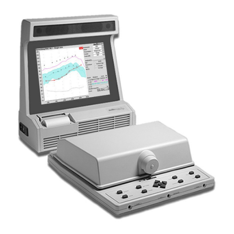
audioscan Verifit VF-1 User manual

VERIFIT®VF-1REAL-EARHEARINGAIDANALYZER
USER’SGUIDE
Version 2.8
November2006
Verifit
®
VF-1

0611 Verifit User’sGuide Version 2.8Page 2
TableofContents
1AboutVerifit.......................................................................................................................7
1.1 Section overview......................................................................................................................7
1.2 Newinthissoftwarerelease.....................................................................................................8
1.3 Electronicuser’sguide..............................................................................................................8
1.4 Warranty,Trademarks,Acknowledgements..............................................................................9
1.5 Noticesforthe European Community........................................................................................9
1.6 Declaration ofEMCcomplianceforthe European Community.................................................10
2Getting Started.................................................................................................................11
2.1 Section overview....................................................................................................................11
2.2 Unpacking and connecting......................................................................................................11
2.3 CD-ROMinstallation...............................................................................................................12
2.4 Microphone connection...........................................................................................................13
2.5 Microphone care.....................................................................................................................14
2.6 Battery pilluseand care.........................................................................................................15
2.7 Mouse, keyboard, barcode scanner........................................................................................15
2.8 External display,printer,speaker............................................................................................16
3GeneralOperation...........................................................................................................16
3.1 Section overview....................................................................................................................16
3.2 Input deviceoperation............................................................................................................17
3.3 Barcode datainput.................................................................................................................18
3.4 Keypad keys...........................................................................................................................19
3.5 Menus, listsand buttons.........................................................................................................20
3.6 Screen messages...................................................................................................................20
3.7 CD-ROMremovaland replacement........................................................................................21
3.8 Softwareupdating...................................................................................................................21
4GeneralSetup..................................................................................................................21
4.1 Section overview....................................................................................................................21
4.2 Dateand timesetup...............................................................................................................22
4.3 Displaysettings......................................................................................................................22
4.4 Saving test setup....................................................................................................................22
5Networking.......................................................................................................................23
5.1 Section overview....................................................................................................................23
5.2 Networking requirements........................................................................................................23
5.3 Networking setup....................................................................................................................24
5.4 Singlecomputerconnection....................................................................................................24
6Printing and Storing Results...........................................................................................25
6.1 Section overview....................................................................................................................25
6.2 Internalprinterpaperloading..................................................................................................26
6.3 Barcodes, headersand commentson printouts.......................................................................27
6.4 Localprintersetup..................................................................................................................27
6.5 Printing toaUSBmemorystick...............................................................................................28

0611 Verifit User’sGuide Version 2.8Page 3
6.6
Network printersetup..............................................................................................................29
6.7 Printing toanetwork file.........................................................................................................30
6.8 Datastorage toanetwork file.................................................................................................30
6.9 Datastorage using NOAH......................................................................................................31
6.10 NOAH3moduleuse...............................................................................................................32
7Hearing InstrumentTestsSetup.....................................................................................33
7.1 Section overview....................................................................................................................33
7.2 HIT singleordualview...........................................................................................................33
7.3 Graph ortableformat..............................................................................................................34
7.4 Output orgainscale...............................................................................................................34
7.5 Hide orShowHITcurves........................................................................................................34
7.6 1996 or2003 ANSI standard...................................................................................................34
7.7 ANSItestfrequencies.............................................................................................................35
7.8 HIT calibration facts................................................................................................................35
7.9 Calibration of HIT referencemicrophone.................................................................................36
7.10 Calibration checkforcouplermicrophone...............................................................................37
7.11 Coupling the hearing instrument.............................................................................................38
7.12 Positioning the hearinginstrument..........................................................................................39
8ANSIS3.22 Hearing AidTests.........................................................................................39
8.1 Section overview....................................................................................................................39
8.2 ANSI S3.22-1996 facts...........................................................................................................40
8.3 ANSI S3.22-2003 facts...........................................................................................................40
8.4 ANSI 1996 Linearand AGCtests............................................................................................41
8.5 ANSI 2003 Linearand AGCtests............................................................................................42
8.6 ANSItest results.....................................................................................................................43
8.7 ANSIinput-outputcurves........................................................................................................44
8.8 ANSItelecoilterminology........................................................................................................45
8.9 ANSItelephone simulator(TMFS) test....................................................................................46
8.10 ANSItest loop test..................................................................................................................47
8.11 Telecoiltest results.................................................................................................................47
9OtherHearing InstrumentTests.....................................................................................48
9.1 Section overview....................................................................................................................48
9.2 Harmonicdistortion.................................................................................................................48
9.3 Directional function test..........................................................................................................49
9.4 Directional ITEpositioning......................................................................................................50
9.5 Directional BTEpositioning.....................................................................................................51
9.6 Directional HIT procedure.......................................................................................................52
9.7 Multicurveprocedure..............................................................................................................52
9.8 Multicurveresults....................................................................................................................53
9.9 Spectral analysisinMulticurve................................................................................................53
9.10 Battery draintest....................................................................................................................54
9.11 Manualcontrolprocedure.......................................................................................................55

0611 Verifit User’sGuide Version 2.8Page 4
9.12
Sound level meterusing manualcontrol..................................................................................55
10 Real-EarMeasurementSetup......................................................................................56
10.1 Section overview....................................................................................................................56
10.2 External REM speakersetup..................................................................................................57
10.3 REM calibration facts..............................................................................................................58
10.4 Calibration of REMprobe microphone....................................................................................58
10.5 Calibration checkforprobe module.........................................................................................59
10.6 MaxTMSPLsetup.................................................................................................................60
10.7 ABRnHL toeHL setup...........................................................................................................60
10.8 Positioning the client...............................................................................................................61
10.9 Positioning the probe tube......................................................................................................61
11 REMScreenSetup.......................................................................................................62
11.1 Section overview....................................................................................................................62
11.2 REM singleordualview.........................................................................................................62
11.3 Graph, tableor2cc targetformat............................................................................................63
11.4 SPLorHL scale.....................................................................................................................63
11.5 Hide orshowREM curves......................................................................................................64
12 Real-EarDirectionalTest.............................................................................................65
12.1 Section overview....................................................................................................................65
12.2 REM directionaltesting...........................................................................................................66
13 REMManualControl....................................................................................................67
13.1 Section overview....................................................................................................................67
13.2 Manualcontrolmeasurements................................................................................................67
13.3 Sound level meterusing REM probe.......................................................................................68
14 Sensoryloss simulator................................................................................................69
14.1 Sensory loss simulatordescription..........................................................................................69
14.2 Sensory loss simulatoroperation............................................................................................69
15 Occlusion EffectTest...................................................................................................70
15.1 Occlusion effectmeasurement................................................................................................70
16 RECD (real-eartocouplerdifference).........................................................................71
16.1 Section overview....................................................................................................................71
16.2 RECD facts............................................................................................................................71
16.3 RECD couplerresponse.........................................................................................................72
16.4 RECD real-earresponse.........................................................................................................73
16.5 RECD results..........................................................................................................................74
17 Insertion Gain...............................................................................................................75
17.1 Section overview....................................................................................................................75
17.2 Insertion gaininSPL...............................................................................................................75
17.3 Insertion gaininHL.................................................................................................................76
17.4 Audiometricdataentry............................................................................................................77
17.5 REUR measurement procedure..............................................................................................78
17.6 REARmeasurement procedure..............................................................................................79

0611 Verifit User’sGuide Version 2.8Page 5
17.7
SII calculation inInsertion gain...............................................................................................80
17.8 CROSfitting using Insertion gain............................................................................................81
18 Speechmap®...............................................................................................................82
18.1 Section overview....................................................................................................................82
18.2 Speechmap facts....................................................................................................................82
18.3 DSL5.0inSpeechmap...........................................................................................................83
18.4 DSL5.0changes....................................................................................................................84
18.5 NAl-NL1 inSpeechmap..........................................................................................................84
18.6 Using Speechmap..................................................................................................................85
18.7 Screen tour-unaided screen..................................................................................................86
18.8 Screen tour-aided screen......................................................................................................86
18.9 REM orS-REM mode.............................................................................................................87
18.10 SII calculation inSpeechmap..............................................................................................88
19 SpeechmapFitting Procedures...................................................................................89
19.1 Section overview....................................................................................................................89
19.2 Assessment dataentry...........................................................................................................89
19.3 Assessment datachoices-1..................................................................................................90
19.4 Assessment datachoices–2.................................................................................................91
19.5 Fitting totargetsforsoftspeech..............................................................................................92
19.6 Fitting totargetsforloud sounds.............................................................................................93
19.7 Fitting totargetsformid-levelspeech......................................................................................94
19.8 Open fittingsinSpeechmap....................................................................................................94
19.9 FMfitting and verification........................................................................................................95
19.10 CROSfitting inSpeechmap................................................................................................96
20 SpeechmapTechnicalDetails.....................................................................................97
20.1 Section overview....................................................................................................................97
20.2 Speechmap stimuli.................................................................................................................97
20.3 Stimuluslevels.......................................................................................................................98
20.4 Microphone locationeffects....................................................................................................99
20.5 Speechsignalanalysis.........................................................................................................100
21 Troubleshooting.........................................................................................................101
21.1 Section overview..................................................................................................................101
21.2 Self testfailures....................................................................................................................101
21.3 HIT high distortion ornoise...................................................................................................102
21.4 HIT curvesinconsistent........................................................................................................102
21.5 HIT curvesdifferfromspecifications.....................................................................................103
21.6 HIT speakeroverdriven........................................................................................................103
21.7 No HIT referencemic. detected............................................................................................103
21.8 InvalidHIT calibration...........................................................................................................104
21.9 No REM ref. mic. detected....................................................................................................104
21.10 InvalidREMcalibration.....................................................................................................104
21.11 REM speakeroverdriven...................................................................................................105

0611 Verifit User’sGuide Version 2.8Page 6
21.12
Barcode scannermalfunction............................................................................................105
22 TechnicalSpecifications...........................................................................................106
23 Glossary......................................................................................................................107
24 References..................................................................................................................111
25 Appendix1:AudioNote2.1VERIFITandRM500SLTestSignalsand Analysis.....114

0611 Verifit User’sGuide Version 2.8Page 7
TheAudioscan
®
Verifit
®
User’sGuideVersion2.8
1 AboutVerifit
1.1 Section overview
FastFacts1.1:VerifitHelptopics
Thissectionprovidesalistingoffeatures
newinthissoftwarerelease
,
instructionsfor accessing theelectronicUser’sGuide, contact, warranty and
trademarkinformationand notices forthe EuropeanCommunity.
Helpisavailableon thefollowing topicsbypressing <Help>
2: GettingStarted 12:Real-EarDirectionalTest
3: GeneralOperation 13:REMManualControl
4: GeneralSetup 14:Sensoryloss simulator
5: Networking 15:OcclusionEffectTest
6: PrintingandStoringResults 16:RECD (real-eartocouplerdifference)
7: HearingInstrumentTestsSetup 17:InsertionGain
8: ANSIS3.22HearingAidTests 18:Speechmap®
9: OtherHearing Instrument Tests 19:SpeechmapFittingProcedures
10:Real-EarMeasurementSetup 20:SpeechmapTechnicalDetails
11:REMScreenSetup 21:Troubleshooting
Inadditionyouwill findaglossary, referencesandmoreinformationinthe
electronicuser’sguide ontheAudioscan softwareCD.

0611 Verifit User’sGuide Version 2.8Page 8
1.2 Newinthissoftwarerelease
FastFacts1.2:Newinthissoftwarerelease
1.3 Electronicuser’sguide
FastFacts1.3:Electronicusersguide
Software2.8
intro
duces
thefollowing significant
additionsand changes
:
1) A Sensory Loss Simulator (SLS)whichprovidesanaccuratesimulationof
cochlearhearing loss forparents,teachersandotherstoexperience.
2)DSL®5, whichprovidestargetsforadults,allowancesforABRandbone
conductionthresholdsandspeechtargetsforthestimuluslevelselected. (Note
thattargetsdo notappearuntil anREARtesthasbeenstarted.)
3)OpenFitting protocolinSpeechmapwhichcan beusedtofit instrumentswith
large ventsoropenearmolds.
4) A new calibrated speechpassage toaugmentthe“carrots”passage.
5) Screenimagesand test datamaybesavedtofilesona USBmemorystick.
6) Support for PostScript printers, including colorlaserprinters.
7)Realtimermslevels forbroadbandsignalslikespeechandpinknoise.
8) The Scroll wheel on amousemaybeusedtotraverselonglistsandHelp.
9)RECD measurements arenowless sensitivetoambientnoise.
10)MPO toneburstshavebeenlengthenedto128msforbettercorrelation with
loudnessperception.
11)Input-Output screensnowhaveacursorreadout.Left click onanygraph.
12)Newcalibration &equalization signalsimproveaccuracy andnoiserejection.
13)Speechlevel nowgoesdownto50dBSPL.
14)Hatching legends andcurvenumbersareshownonprintoutsforbetter
identificationonblack andwhiteprintouts.
Pleaseconsult therelevant sectionofthisUser’sGuideorHelpformoredetails.
Aprintableuser’sguide isonthe AudioscanCD-ROMsuppliedwithanew
instrumentormailedasasoftwareupdate. Youmaywanttocopyit toyourPC
beforeinstalling theCD-ROMintheVerifit. Onceinstalled inthe Verifit, the CD-
ROMmaybe laterremoved byfollowingtheinstructionsin 3.7: CD-ROMremoval
andreplacement.
A.pdffileviewer, suchasAcrobat Reader(5.0orhigher) orFoxit Readeris
requiredtoviewthe User’sGuide. Foxit ReaderissuppliedontheCD-ROM.
1) Insert theCD-ROMintotheCD driveon yourcomputer.
2) Select MyComputer,then theCD driveandthe User’sGuide folder.
3) Toinstall Foxit Reader, copyFoxitReader.exetoanappropriatelocationon
yourPC. TorunFoxitReader.exedoubleclick it.
4) ToviewtheUser’sGuide,double-click the VerifitUsersGuide.pdffile.
TheUser’sGuidemayalsobedownloadedfrom www.audioscan.com.

0611 Verifit User’sGuide Version 2.8Page 9
1.4 Warranty,Trademarks, Acknowledgements
FastFacts1.4:Warranty, trademarks, acknowledgements
1.5 NoticesfortheEuropeanCommunity
FastFacts1.5:NoticesfortheEuropeanCommunity
The
AudioscanVerifitmodelVF
-
1
ismanufactured byEtymonicDesignInc.,
41 ByronAve.,Dorchester, Ontario, CanadaN0L 1G0.
Phone: 800-265-2093(USAonly); 519-268-3313Fax: 519-268-3256
www.audioscan.com Email: info@audioscan.com or service@audioscan.com
Warranty: TheVerifit modelVF-1iswarrantedagainstdefectsfortwoyearsfrom
dateofpurchase.Withinthisperiod, itwill be repaired without chargeforparts,
labororreturnshippingwhenreturned prepaidtoyourauthorized Audioscan
serviceagent. Thiswarrantydoesnotapplytobatterysubstitutes(pills),
whichcarrya90daywarranty, ortoequipmentthat, inoursolejudgement,has
been subjecttomisuse, orunauthorizedalterationorrepair.
Trademarks: Audioscan,Verifit, SpeechmapandQuikscanareregistered
trademarks ofEtymonicDesignInc. DSLisaregisteredtrademarkof The
UniversityofWesternOntario. HPLASERJETisaregisteredtrademarkof
Hewlett-PackardCompany. IBMisaregisteredtrademarkof International
Business MachinesCorporation.K-AMPisaregisteredtrademarkof Etymotic
ResearchInc.KEMARisaregistered trademarkof KnowlesElectronicsInc.
QUESTisatrademarkofQuest TechnologiesInc.PostScriptisaregistered
trademarkof AdobeSystems,Inc.
Acknowledgements: DSL5.0isused underlicensefromtheUniversityof
WesternOntario(UWO)whichissoleyresponsibleforitscontent. We
acknowledgethe supportreceivedfrompastandpresentstaff at theNational
CentreforAudiologyatUWOinimplementingtheDSLmethod.Weareindebted
totheUniversityof MemphisHearingAidResearchLaboratoryforpermission to
usesomeof theirrecordedspeechmaterial.
AuthorisedAudioscan representativewithintheEuropeanCommunity:
PCWerthLtd.,AudiologyHouse, 45NightingaleLane,London SW128SPUK
Phone: +44(0)2087722700 www.pcwerth.co.uk
ElectromagneticCompatability(EMC)
MedicalelectricalequipmentneedsspecialprecautionsregardingEMCandneeds
tobe installed and put intoserviceaccordingtothefollowinginformation:
vThe Verifitshouldnotbeused adjacenttoorstacked onotherequipment. If
thisisnecessary, itsoperation shouldbeverified asnormalinthis
configuration.
vPortableand mobileRFcommunicationsequipment can affectmedical
electricalequipmentandmayaffecttheperformanceof the Verifit.
vThe Verifithasnotbeentestedforimmunitytoelectromagneticdisturbances.
Performancedegradationduetosuchdisturbances(including electrostatic
discharge)isconsiderednormalandacceptable.

0611 Verifit User’sGuide Version 2.8Page 10
1.6 Declaration ofEMCcompliance fortheEuropeanCommunity
FastFacts1.6:Declaration ofEMCcompliance fortheEuropeanCommunity
The complianceslistedinthe followingtablearemet withthesuppliedRECD
transducer, microphones,headphones, mouseandkeyboardconnected andwith
unterminatedspeakercables(2), USB cables(2), ethernet cable,parallelprinter
cable, serialcableandVGAdisplaycableconnected.Theconnection of other
devicesmayresult inincreasedemissions.
Guidance and manufacturer’sdeclaration -electromagneticemissions
The Verifit isintendedforuseinthe electromagneticenvironmentspecifiedbelow.
The useroftheVerifit shouldassurethat it isusedinsuchanenvironment.
Emissionstest Compliance
Electromagneticenvironment -guidance
RFemissions
CISPR11 Group1
The VerifitusesRFenergyonlyforitsinternal
function. Therefore, itsRFemissionsarevery
lowand not likelytocauseanyinterferencein
nearbyelectronicequipment.
RFemissions
CISPR11 Class A
Harmonicemissions
IEC61000-3-2 Class A
Voltagefluctuations/
flickeremissions
IEC61000-3-3 Complies
The Verifit issuitableforuseinall
establishmentsotherthandomesticandthose
directlyconnectedtothepubliclow-voltage
powersupplynetworkthat suppliesbuildings
usedfordomesticpurposes.

0611 Verifit User’sGuide Version 2.8Page 11
2 GettingStarted
2.1 Section overview
FastFacts2.1:Getting started
2.2 Unpacking and connecting
FastFacts2.2:Unpacking and connecting
ThissectionprovideshelponunpackingtheVerifitandconnectingvarious
componentsand accessoriesandoninstallingtheCD-ROM.
Thefollowing topicsarecoveredinthissection:
2.2: Unpackingand connecting
2.3: CD-ROMinstallation
2.4: Microphoneconnection
2.5: Microphonecare
2.6: Batterypill useand care
2.7: Mouse, keyboard, barcodescanner
2.8: Externaldisplay, printer,speaker
1)
Carefullyunpack thetwopartsof the Verifitand check thecontentsofthe
shippingboxagainsttheenclosedpackinglist.Notethat somepartsmaybe
packed insidethetest chamber.
2) Connectthetwo15 pincablesfromthe connectorsontherearofthetest
chambertotheconnectorsonthefrontofthemaindisplayunit asshown.The
topsideof eachconnectorislabeled toassistyou. Take carenottoforcethe
connectorsasthepinsareeasilybent. Bothshort (asshown)andlong
cablesareprovided forflexibilityinlocatingthetwopartsoftheinstrument.
3) Connectthepowercordtothe socketnext tothe powerswitchontheleft side
ofthemaindisplayunit. Plug theotherendintoa grounded 100–240 volt
poweroutlet.

0611 Verifit User’sGuide Version 2.8Page 12
2.3 CD-ROMinstallation
FastFacts2.3:CD-ROMinstallation
Operatingsoftware, sometest signals, the online Helpfilesandaprintableuser’s
guideareall onthe VerifitCD-ROMsuppliedwiththeinstrument. TheCD-ROM
mustbepresentintheCD drivefornormalinstrumentoperation. Operation
without theCD ispossiblebutSpeechmap tests,SensoryLossSimulator,and
Helpwill not work. The CD drivedoorislocatedonthe rearofthemaindisplay
unitbelowthe externalspeakerjacks. ThedooroftheCD drivewill openonly
whenpowerisfirstapplied. Ifnecessary, toopenthe CD drivewithoutpower,
insert theendof asmall screwdriver(orapaperclip)intheholenearthelighton
theCD drivedoor.
1) SetthepowerswitchtotheONposition. The powerswitchshouldlight andthe
displayscreen shouldbecomeactive.
2) Press theOPENbuttononthedooroftheCD drive. The doorshouldopen.
3) SetthepowerswitchtotheOFFposition.
4) PositiontheVerifit CD-ROMon thespindle,printedsideup,and pressgently
downwarduntil it snapsintoplace.
5) Gentlypushthe CD drivedoorinwarduntil itsnapsclosed.
6) SetthepowerswitchtotheONposition.

0611 Verifit User’sGuide Version 2.8Page 13
2.4 Microphoneconnection
FastFacts2.4:Microphoneconnection
1)
Plugthereferencemicrophoneand thecouplermicrophoneintotheconnectors
inthetestchamberasshown.
2) Plugtheprobemicrophoneassembliesintotheprobeconnectorslocated atthe
frontedgeof thebuilt-inkeypadasshown.
NOTE:Amicrophoneextension cable(VA-130)isavailablefromAudioscan.
Standardaudioextension cablesshouldnotbeused.Theywillsubstantially
increasenoiselevels.

0611 Verifit User’sGuide Version 2.8Page 14
2.5 Microphonecare
FastFacts2.5:Microphonecare
Couplermicrophone:
1)DO NOT twistthecablewhenattachingacouplertothecouplermicrophone.
Turnonlythecouplerorunplugthecouplermicrophonebeforeturning it.
2)DO NOT leavethe couplermicrophoneplugged inwhentransporting.
3)DO makesurethatthe2cc coupleristightlyscrewed tothecouplermicrophone
whenperforminghearing instrumenttests. Couplerleakagecancause
feedbackand erraticresponsecurves.
4)DO makesurethe #13tubingontheBTE(HA-2)couplerisfree fromany
cracks/tears.
5)DO makesurethatanyreplacement#13tubing used ontheBTEcoupleris.38
inchesinlength.
Probemicrophones:
Debriscanaltertheprobemodulereferencemicrophonecalibrationandfrequency
responseandcanpermanentlyclogtheprobemoduleport.
1)DO NOTreuseprobetubes. Debrisandliquidfromcleaningattemptscan
lodgeinthe enlargedbaseoftheprobetubeandsubsequentlyclog theprobe
microphoneport.
2)DO NOT attempttoopenorrepairtheprobemicrophone.Attemptingtorepair
theprobemodulemayleadtodamageoralterationof the factorycalibration.
3)DO keep theprobemoduleandprobetubesinacleanarea.
4)DO stowtheprobemodulewhennot inuseorwhen transportingtheVerifit.

0611 Verifit User’sGuide Version 2.8Page 15
2.6 Batterypilluseand care
FastFacts2.6:Batterypill useand care
2.7 Mouse, keyboard, barcodescanner
FastFacts2.7:Mouse, keyboard, barcodescanner
The Verifit maybe operatedfromthe
built
-
inke
ypad
,a
mouse
orastandard
computer(QWERTY) keyboard,whichmayalsobe usedtoenterheadersand
commentsonprintouts. PS-2connectorsforthesedevicesareprovidedonthe
rearof the maindisplayunit.AUSB mouseorkeyboardmaybepluggeddirectly
intoeitheroftheUSBportsprovided. See 3.2: Inputdeviceoperation.
Anoptional barcodescanner maybe connectedtoaUSBport toenterthreshold,
UCLand RECD datadirectlyfromaVerifitorRM500SLprintout. Barcoded
thresholddataprintedbysomeGrason-Stadleraudiometricequipmentmayalso
be scanned.Scannersotherthanthat suppliedbyAudioscanmaynotworkand
arenotsupportedbyAudioscan.
IntheEuropeanCommunity, ifthisdeviceisconnectedtooneormore
otherdevicestomakeasystem, theCEmarkonthisdeviceisonlyvalidif
theotherdevicesinthe systemcarryaCEmarkinrespect of the Medical
DeviceDirectiveandifthesupplierhasstatedthattherequirementsof the
MedicalDeviceDirectivewill bemetforthisparticularcombination.
The thinconnecting stripof
eachbatterypillisfragile
.Wheninsertingpillsinto
hearing instrumentbatterycompartments, takecarethatthisstripisnotpinched or
bent severelyasthebatterydoorisclosed.
1) Select abatterypill that isappropriatelysizedforthe hearinginstrument that
you aretesting.
2) Insert thepill intothe hearinginstrument, carefullyclosingthe batterydoorover
thethinconnectingstrip.
3) Plugthepill’scableintothebatterypill jack insidetheVerifitHITtestchamber
(tothe rightof thecouplermicrophoneconnection).
4) Turnthehearinginstrumenton.

0611 Verifit User’sGuide Version 2.8Page 16
2.8 Externaldisplay, printer, speaker
FastFacts2.8:Externaldisplay, printer, speakers
3 General Operation
3.1 Section overview
FastFacts3.1:Generaloperation
The Verifit isoperatedbyusingthebuilt-inkeypad, aUSB orPS-2QWERTY
keyboard(not included)oraUSBorPS-2computermouse.Anyof thesepointing
devicescanbeused toselect itemsfrommenus,operateon-screen buttonsand
toenteraudiometricdata.Inaddition,audiometricdataprintedinbarcode form by
theVerifitorsomeGrason-Stadlerproducts,maybe scanned intotheVerifit.
Thissection coversthefollowing topics:
3.2: Inputdeviceoperation
3.3: Barcode datainput
3.4: Keypadkeys
3.5: Menus, listsandbuttons
3.6: Screenmessages
3.7: CD-ROMremovalandreplacement
3.8: Softwareupdating
An
externalmonitor
maybe connectedtothe15
-
pinconnectoron the
rear
of the
maindisplayunit. It will automaticallydisplaywhatisonthe internalscreen. The
monitorshouldbecapableof 800x600resolution.
An externalprinter maybeconnectedtotheparallelprinterconnectorortoone
oftheUSBports. It maybecolororblack &whitebutit mustbePCL3, PCL5or
Postscriptcompatible. The externalprintermust first beselectedinSetup. See
6: PrintingandStoringResults
Connectorsfor externalfrontand backreal-earmeasurementspeakers are
provided.SpeakersareavailablefromAudioscanbutanysmall 4-8ohmspeaker
havingasmoothfrequency responseandgoodefficiency maybeused.Therear
externalspeakerisautomaticallyselectedwhenrequired byatestbut thefront
speakermustfirstbeselectedinSetup. See 10.2:ExternalREMspeakersetup
IntheEuropeanCommunity, ifthisdeviceisconnectedtooneormore
otherdevicestomakeasystem, theCEmarkonthisdeviceisonlyvalidif
theotherdevicesinthe systemcarryaCEmarkinrespect of the Medical
DeviceDirectiveandifthesupplierhasstatedthattherequirementsof the
MedicalDeviceDirectivewill bemetforthisparticularcombination.

0611 Verifit User’sGuide Version 2.8Page 17
3.2
I
nput
d
evice
operation
FastFacts3.2:Inputdevice operation
The Verifit maybe operatedbymeansofthe
built
-
inkeypad
, anexternal
mouse
oranexternalQWERTY keyboard. Thesedevicesareused tosummonon-
screenmenusandselect itemsfromthem, tooperateon-screenbuttonsandto
input data. The scroll wheel on thistype ofmousewill scroll throughlonglistsin
list boxesandinHelp. Clicking therightmouse buttongeneratesan imageof
thekeypad whichmaybeoperated bythemouse. Clicking theleft mouse
button when themousepointerison agraphwill displaya screencursor witha
digitalreadoutofXandYco-ordinates. Clickingagainwill dismiss the cursor.
Function Keypad QWERTY Mouse
SummonHelpmenu <Help> F1 Right click
SummonSetup menu <Setup> F2 Right click
SummonTest menu <Tests> F3 Right click
SummonSessionmenu <Session> F4 Right click
Switchbetween earsor
Switchbetween A/BData <Left/Right> F5 Right click
Print <Print> Print Scrn Right click
Moveacrossscreencolumns óArrows óArrows Movemouse
Movewithinascreencolumn ôArrows ôArrows Movemouse
Select ahighlighteditemor
operateascreen button Roundkey
(<PICK> key) Numeric
EnterKey Left click
Enternumericdata Select point on
chart Numeric
keypad Left click on a
point onchart
Entertext Not possible Anykey Not possible
Proceedfromcurrent state <Continue> Enter↵Click Continue
Reverttopreviousstate <Cancel> Esc Click Cancel
Alsosee 2.7: Mouse, keyboard,barcodescanner and 3.3:Barcodedatainput

0611 Verifit User’sGuide Version 2.8Page 18
3.3 Barcodedatainput
FastFacts3.3:Barcodedatainput
In
Speechmap
and
Insertion gain
tests,audiometricdatainbarcodeform on
a
VerifitorRM500SLprintoutmaybeentered byscanningtheappropriatebarcode.
InSpeechmap, threshold, UCL, RECD,transducer,age,andABRnHLtoeHL
conversionfactorsareencoded. InInsertiongain, thresholdandtransducertype
areencoded.Thetypeof dataandtheear(left, rightorleft/right)isshownbelow
thebarcode.Onlydataforthedisplayedearareimported(dataforbothearsin
dualview).Barcodesmaybescannedinanyorderanditdoesnotmatterifthe
barcodeis“upsidedown”.
1) Select SpeechmaporInsertiongainfromthe Testsmenu.
2) Holdtheprintout sothatthebarcodetobescannedisflat. Withthescanner6”
-8”fromthebarcode,pressthe triggeronthescannerand centerthe
illuminatedredlinealong thelengthofthebarcode.
3) When thescanissuccessful,thescannerwill
“beep”, theredlinewill extinguishanda
BarcodeEntryposterwill appearon the
screen. Agreencheckmarkonthe poster
showswhichdatahavebeenaccepted.A
message will adviseifthebarcode doesnot
containdataforthescreenyouareviewing.
4) When all desireddatahavebeenaccepted,
select[Done] toapplythedata.
See6.3:Barcodes,headersandcommentson
printouts. BarcodesonsomeGrason-Stadler
printoutsmayalsobescannedintotheVerifit.

0611 Verifit User’sGuide Version 2.8Page 19
3.4 Keypadkeys
FastFacts3.4:Keypadkeys
KeypadButton Function
<Help> Summoncontext-sensitiveHelpScreen.
<Setup> SummonSetup Menucontaining alistofVerifit
featuresthatcanbemodified.Anymodifications
madewill bemaintainedafterpoweroff.
<Tests> SummonTest SelectionMenu containingalist of the
availabletest procedures.
<Session> SummonSessionDataMenu toeraseorexportdata
<Left/Right> Used inthe SingleViewModetoalternatebetween
earsorA/BData. UsedintheDualViewModeto
navigatebetweenearsortestpanels.
<Print> Printon internalorexternalprinterorprint tofile.
óArrows Moveacrossscreencolumns.
ôArrows Movewithinascreencolumn.
RoundKey(<PICK> key)
Select ahighlighteditemoroperateascreenbutton.
<Continue> Proceedfromcurrent state.
<Cancel> Reverttopreviousstate.

0611 Verifit User’sGuide Version 2.8Page 20
3.5 Menus, listsand buttons
FastFacts3.5:Menus, listsand buttons
3.6 Screenmessages
FastFacts3.6:Screenmessages
Menu
Setup Box
ListBox
ScreenButtons areidentified byacirclewithinaraised block andarelocated
at therighthandendof alineof screen text. Ascreenbuttonhighlightedusingthe
keypad oraQWERTYkeyboardissurrounded byaheavyline. Ascreen button
highlightedbythemousepointerchangescolorfromlight todarkgray.A
highlightedscreen buttonisoperatedbypressingthe<PICK> (round)keyonthe
keypad,the Enterkeyon akeyboardorbyclickingthe left mousebutton. This
processalsoselectsthehighlightediteminalistbox.
Therearethree different typesof screenbuttons:
When selected,a Menu Button displays amenu,asetupboxoratest screen.
When selected,a ListButton displays adrop-downlist box.
Thecurrentlist itemisshowninthewindow.
When selected,a ToggleButton alternatesbetweenstates.
Thecurrentstateisshowninthewindow.
The
Titleba
r
(toplineof thedisplay
screen)informsyouof theselectedTest (e.g.,
Multicurve)andthecurrentPresentation(SinglevieworDualview).
The Messagebar (bottomlineof the displayscreen)suggeststhe next stepina
testorinformsyou ofthestateof the instrument orconditionsthatcouldaffectyour
data. Forexample, itwill inform youifthe microphonesneedtobecalibrated.
Other manuals for Verifit VF-1
1
Table of contents
Other audioscan Measuring Instrument manuals
