FoamPRO 3012 User manual

Unit
Serial
Number
System 3012
Model 3012
INSTALLATION AND
OPERATION MANUAL
Form 836
6/19
All quality FoamPro products are ruggedly designed, accurately machined, carefully assembled, thoroughly inspected
and tested. In order to maintain the high quality of your unit, and to keep it in a ready condition, it is important to follow
the instructions on care and operation. Proper use and good preventive maintenance will lengthen the life of your unit.
ALWAYS INCLUDE THE UNIT SERIAL NUMBER IN CORRESPONDENCE.
FoamPro • 26 Southern Blvd. • Nesconset, NY 11767 USA • 800-533-9511 • FAX 816-892-3178

2
Installation and Operation Manual
TABLE OF CONTENTS
SECTION PAGE
1 SAFETY ............................................................................................................................ 3
2 A QUICK LOOK AT HOW THE SYSTEM WORKS .......................................................... 5
3 SYSTEM COMPONENT DESCRIPTION ......................................................................... 7
4 INSTALLER SUPPLIED PARTS....................................................................................... 9
5 INSTALLATION PLANNING ............................................................................................ 12
6 FOAM PUMP AND HYDRAULIC CONTROL VALVE INSTALLATION ........................... 13
7 HYDRAULIC PLUMBING INSTALLATION...................................................................... 14
8 WATER AND FOAM PLUMBING COMPONENT INSTALLATION ................................. 16
9 ELECTRICAL EQUIPMENT INSTALLATION.................................................................. 21
10 MAKE SURE EVERYTHING IS WORKING RIGHT ........................................................ 27
11 CALIBRATION AND SETUP ........................................................................................... 30
12 OPERATING INSTRUCTIONS........................................................................................ 33
13 MAINTENANCE............................................................................................................... 40
14 TROUBLESHOOTING..................................................................................................... 41
15 SPECIFICATIONS ........................................................................................................... 46
16 WARRANTY ......................................................................................................Back Cover
NOTE TO SYSTEM INSTALLERS
IMPORTANT: Please provide a copy of the FoamPro manual to the end user of the equipment.
For additional FoamPro manuals, contact by FAX 816-892-3178, web site www.foampro.com,
or call 800-533-9511. Request Form No. 836.

3
Installation and Operation Manual
System 3012
The following special notices are used to notify and
advise the user of this product of procedures that may be
dangerous to the user or result in damage to the product.
NOTE: Notes are used to notify of installation,
operation, or maintenance information that is
important but not safety related.
CAUTION: Caution is used to indicate the presence
of a hazard, which will or can cause minor injury or
property damage if the notice is ignored.
WARNING: Warning denotes that a potential
hazard exists and indicates procedures that must
be followed exactly to either eliminate or reduce
the hazard, and to avoid serious personal injury, or
prevent future safety problems with the product.
DANGER: Danger is used to indicate the presence
of a hazard that will result in severe personal injury,
death, or property damage if the notice is ignored.
• Do not pump at pressures higher than the maximum
recommended pressure. [400 PSI (28 bar)]
• Do not permanently remove or alter any guarding
devices or attempt to operate the system when those
guards are temporarily removed.
• Always disconnect the power source before
attempting to service any part of the pump.
• Release all pressure within the system before
servicing any of its component parts.
• Drain all concentrate and water from the discharge
system before servicing any of its component parts.
• Check all hoses for weak or worn conditions after
each use. Ensure that all connections and fittings are
tight and secure.
• Use only pipe, hose, and fittings from the foam pump
outlet to the injection point, which are rated at or
above 400 psi (28 BAR) minimum rating, at which the
water pump system operates.
• Use only pipe, hose, and fittings from the hydraulic
oil pump to the foam pump hydraulic motor, which
are rated at 3000 psi (207 BAR) minimum working
pressure or better and are approved for mobile
hydraulic system use.
• Any electrical system has the potential to cause
sparks during service. Take care to eliminate
explosive or hazardous environments during service/
repair.
• Rotating drive line components can cause injury. Be
careful of rotating components when adjusting load
sense pump compensator.
• Slowly loosen the foam pressure line fittings and
allow the pressure to escape. Protect face and eyes
from any potential spray which may occur.
CAUTION: Do not attempt to operate the system at or
above a temperature of 160°F (71°C).
WARNING: Ensure that the electrical source of power
for the unit is a 12 or 24 Volt, negative ground DC
system. Power and ground lines must come directly
from the battery without any connections to other high
power devices, such as primer pumps, hose reels,
light bars, etc. Power required for the valve driver box
on the hydraulic motor-driven foam pump must have a
minimum current rating of at least 5 AMPS.
CAUTION: Periodically inspect the pump and the
system components. Perform routine preventive
maintenance as required. Failure to perform routine
maintenance may cause damage to the system.
See the maintenance section of this manual for
recommended maintenance procedures and intervals
between maintenance work.
NOTE: Read and understand these installation
instructions before proceeding with the equipment
installation.
CAUTION: Use only approved petroleum-base
hydraulic fluids meeting the specifications as noted
in Section 4. Never mix fluid types. Ensure all hoses
and seals are compatible with fluids used. Do not use
water or glycol-based fluids. Do not use phosphate
ester-type fluids.
1 Safety Before attempting to install a FoamPro System 3012, read all
of the following safety precautions and follow carefully.

4
Installation and Operation Manual
CAUTION: Dirt and contaminant’s are the primary
causes of premature wear and failure in any hydraulic
system. Use extreme care during assembly and
service to keep contaminant’s out of the system.
WARNING: Always disconnect the ground straps,
electrical wires and control cables from the Digital
Display Control Module and all other FoamPro
equipment before electric arc welding at any point on
the apparatus. Failure to do so will result in a power
surge through the unit that could cause irreparable
damage.
CAUTION: All DOT, SAE or other applicable
standards must be followed when installing
the hydraulic supply system. Pay close attention
to engine and transmission manufacturer drive
limitations.
CAUTION: Never attempt to cut or lengthen the
molded cables. Doing so will result in RFI/EMI
interference. Contact the factory if molded cables of
a different length are required.
CAUTION: To ensure the integrity of fitting
connections in the hydraulic system, use only SAE
JIC 37° flare or equal type hose connections.
CAUTION: To prevent damage to the hydraulic motor
seal, the motor case drain must have its own 1/4 inch
(6.3 mm) inside diameter hose installed to return
hydraulic oil to the reservoir.
WARNING: The load sense pump compensator is
preset at the factory for proper operation. DO NOT
adjust the load sense compensator.
CAUTION: The cables shipped with each FoamPro
3012 are tested at the factory with that unit. Improper
handling and forcing connections can damage these
cables which could result in other system damage.
CAUTION: The foam tank low-level sensor must be
utilized to protect the foam pump from dry running.
Failure to do so will void warranty.
CAUTION: The input power wire is not protected by
the system circuit breaker. Be careful not to damage
or short circuit this wire.
CAUTION: When pouring foam concentrate directly
into the foam pump, the inlet strainer is bypassed.
Make sure contaminant’s are not poured into pump
chamber. Premature pump wear or damage may
result if contaminant’s are allowed to enter pump
chamber.
CAUTION: Do not run the FoamPro 3012 for more
than one minute deadheaded against the pressure
gauge, as the foam pump could be damaged.
CAUTION: When operating the FoamPro in the
“Simulated Mode” function, an outlet for the foam
concentrate must be provided. Otherwise dangerous
excessive pressure may be built up in the apparatus
water piping and/or hoses. This outlet for the foam
concentrate can be provided by turning the “CAL/
INJECT” valve to the “CAL” position. A suitable
container must be provided to collect the foam
concentrate.
CAUTION: Do not mount electronics where they will
be exposed to direct water spray.

5
Installation and Operation Manual
System 3012
2 A Quick Look at How the System Works
The FoamPro 3012 system is an electronic and
hydraulic foam concentrate proportioning system
designed to provide the wide range of foam concentrate
injection rates necessary for both Class A and Class B
foam operations.
The FoamPro system will accurately deliver from 0.1%
to 10.0%, or from 0.1 to 12.0 gpm of foam concentrate
to the foam injection point. The maximum rated
concentrate flow rates obtainable are shown in the
system specifications in Section 15.
The FoamPro 3012 system is a flow-based
proportioning system that measures water flow and
then injects the correct proportional amount of foam
concentrate to maintain the desired percentage.
The basic FoamPro system is shown in Figure 2-1.
The flowmeter measures the water flow and sends
a signal to the Digital Display Control Module. A
speed-sensing device monitors the foam pump output.
Constant comparison of these two information signals
by the controller ensures maintenance of the desired
proportion of foam concentrate at all times based on
water flow rate, independent of any variations in fire
pump intake or discharge pressures. As water flow
increases or decreases, the foam concentrate rate
of injection is increased or decreased automatically
to correspond to water flow, maintaining the proper
concentrate percentage as selected on the Digital
Display Control Module.
CAUTION: If the power to the FoamPro unit fails or
is shut off during operation, the system will remain
in operation at the last setting. DO NOT close the
discharge to the system until the hydraulics are
disengaged. To turn the system off, it is required to
disengage the hydraulic drive PTO.
Foam concentrate is injected directly into the water
stream on the discharge side of the water pump. It is
then fed as foam solution into a standard fog nozzle,
an air-aspirated nozzle, a straight bore nozzle, or into
a CAFS system, by the main fire pump. Since the foam
is injected on the discharge side of the fire pump and
check valves are used at installation, contamination of
the booster tank, fire pump, and relief valve with foam
concentrate is eliminated.
Hydraulic power to operate the foam pump is to be
provided by a separate hydraulic pump driven by the
apparatus system.
Electrical power to operate the foam systems is
provided by the apparatus electrical system.
Order optional system components listed in Section 3
to accommodate system design and requirements. The
components listed have been tested with the FoamPro
systems and provide for optimum system performance.
FoamPro Model 3012 systems will pump Class A
and Class B (Aqueous Film Forming Foam, AFFF,
and Alcohol-Resistant Aqueous Film Forming Foam,
AR-AFFF) to capacity. Many brands of AR-AFFF
exhibit higher viscosity characteristics due to chemical
composition and polymers. As viscosity increases,
diminished flow may affect pump performance. Because
of numerous variables; including pump design, foam
cell configuration, inlet piping/components and system
layout; please contact FoamPro at 800-533-9511 for
application-specific recommendations when foam
viscosities of 2000 cps (Brookfield #3 spindle @ 30 rpm)
or higher are used.

6
Installation and Operation Manual
Figure 2-1 FoamPro 3012 System Layout
Foam Tank
Water Tank
Water Pump
Power & Ground
Connection Pin
A (Red) + 12 VDC
to + 27 VDC Pin B
(Black) Ground
Water Flowmeter
Line Strainer
Foam Pump Assy. Speed Sensor
Check Valve
Check Valve
(Optional)
Main Waterway
Check Valve
Flush Water
Shutoff Valve
Foam Tank
Shutoff Valve
Outboard
Pickup
Foam Injection Point
Single Discharge
Calibrate/Inject Valve
Foam Injection Check Valve
Hydraulic Motor
and Control Valve
Hydraulic Valve
Control Driver
Foam Tank
Low-Level
Sensor
Digital Display Controller
Multiple Discharge
with Manifold

7
Installation and Operation Manual
System 3012
3 System Component Description
The following components are packaged with the
standard FoamPro 3012 system:
1. Digital Display Control Module
2. Molded Cables
3. Foam Pump and Hydraulic Control Valve Assembly
4. Instruction Placard
5. Low-Level Sensor (One required. Not packaged
with the unit. Order separately.)
6. Calibrate/Inject Valve
7. Inlet Line Strainer
8. Check Valve 1/2"’ NPT Foam Injection. This NFPA
1906 (draft) required check valve prevents water
back flowing into foam system.
9. RFI/EMI Suppression Beads
10. FoamPro Paddlewheel Flowmeter or Manifold
(The flowmeter is a required component. The
size is specified and ordered under a separate
part number when the FoamPro is ordered. The
flowmeters are available with 1-1/2", 2", 2-1/2", 3",
and 4" NPT threads; or manifolds with Victaulic-
grooved ends in 1-1/2", 2", 2-1/2", 3” and 4" pipe
sizes. All flowmeters have grooved victaulic ends.
Insert-style flowmeters are available for larger pipe
diameters. Part numbers for the various flowmeters
can be found in Section 15. Up to 4 flowmeter
sensors can be used with the FoamPro System
when a MultiFlo interface is used.)
11. Hydraulic Load-Sensing Pump
1
4
3
2
8
7
6
5
11
10
9

8
Installation and Operation Manual
SYSTEM ACCESSORIES AVAILABLE
FoamPro MultiFlo Interface
Combines 2 to 4 flowmeters
for single point systems
System Placard Solid State Contactor
P/N 2510-0043
Nesconset, NY 11767US
A
Main Waterway Check Valve with Drain Port
Available in stainless steel.
NPT threaded ends with injection and drain ports
System
Specification Placards
Remote Start/Stop
Polypropylene Foam Tank(s)
8, 12 or 20 gallon capacity
Foam Manifold
All stainless steel with main waterway
check valve, water flowmeter, injection
port, and drain port. Victaulic grooved ends
For more information on these accessories, please see publications 856 and PL-21.
Electronic Concentrate
Management System
Electronic control for Dual Tank Systems
with interface to controller
Electronic Concentrate Management System
Electronic control of single or dual tank onboard
systems and an off-board pickup.
2002 Series and larger only
Main Waterway Check Valve
All stainless steel with Victaulic
ends and injection and drain ports
NFPA Calibration and Test Kit
For use with 1600 thru 3012 systems
Dual Injection Management System
Provides capability for switching between
two injection points
Single Tank Flush Kits
Both Internal and External flushing kits

9
Installation and Operation Manual
System 3012
4 Installer Supplied Parts
FoamPro 3012 systems are provided with major
components and accessories required for installation. Due
to differences in chassis and apparatus configurations,
the installer must provide hydraulic coolers, fluids,
reservoir, pipe, hoses, tubing, wire and fittings to satisfy
installation requirements. The following paragraphs list the
specifications for selection of these components. Before
beginning system installation, read this section thoroughly
to make sure the proper components are selected. For
detailed system installation instructions, refer to Sections 5,
6, 7, 8 and 9.
CAUTION: All DOT, SAE or other applicable standards
must be followed when installing the hydraulic system.
Pay close attention to engine and transmission
manufacturer drive limitations.
Hydraulic Pump Drive Selection
The foam pump for the FoamPro 3012 system is powered
by hydraulics. Power for the system comes from hydraulic
oil supplied by a hydraulic pump attached to the apparatus
engine. To obtain optimum performance from the hydraulic
motor-driven foam pump, FoamPro has designed the 3012
system to use a load-sensing, pressure-compensated
hydraulic pump. The FoamPro load-sensing hydraulic
pump provides proper hydraulic fluid flow with reduced heat
load, torque and horsepower requirements.
The FoamPro load-sensing hydraulic supply pump will
provide the correct fluid flow over the widest range of engine
speeds. See system specifications for the maximum required
pump speed to attain maximum performance levels. By
using a PTO ratio greater than 1.0, the minimum engine
speed for full system performance could be idle speed.
A transmission PTO should be used to drive the hydraulic
supply pump. Transmission PTOs have greater torque
capabilities and provide adequate power for the hydraulic
pump. Selection of a PTO transmission with a standard
SAE mounting pad will allow bolting the hydraulic pump
directly to the transmission. The FoamPro load-sensing
hydraulic supply pump has a standard 2-bolt SAE “B”
mounting flange and a 13 tooth, 16/32-pitch splined shaft.
Other shaft configurations are available. The shaft rotation
of the pump is clockwise when looking at the pump shaft, or
counterclockwise when facing the rear of the pump. Check
with the FoamPro factory for other configurations that may
be available. See Section 15 for pump dimensions.
Control of the PTO may be provided by a manual shift
lever, shift cable or solenoid. The manual shift-type PTO
may be left in gear all the time to circulate oil as soon as the
engine is started, since the load-sensing hydraulic pump
will draw less than 2 hp when operating in standby mode.
The PTO shift can be labeled “Service Disconnect.”
When selecting a transmission PTO, it is imperative that
consideration be given to frame clearances and the space
in which the hydraulic supply pump is to be mounted. For
new installations, initial design and planning will eliminate
clearance problems. When the FoamPro 3012 system is
being installed as a retrofit, all clearances must be taken
into account. Consult PTO and chassis manufacturers to
determine dimensions and clearances required.
CAUTION: The use of an accessory drive pad is
not recommended since adequate torque usually
is not available to drive the hydraulic supply pump
and accessories.
Choosing the Proper PTO
It is important to turn the hydraulic pump at the proper
speed to ensure that the correct hydraulic pressure is
produced over the full operating range of the foam system.
When selecting a PTO to drive the hydraulic pump,
compare the maximum RPM for the water pump with the
maximum RPM (2,500 RPM) for the hydraulic pump. Then
select a PTO that will provide the best performance at a
lower RPM.
For Example: the maximum speed you can turn the water
pump is 1,800 RPM. For the 3012 system hydraulic pump,
the minimum speed is 1,350 RPM, and the maximum
speed is 2,500 RPM. It is recommended to choose a PTO
with a range of 1 - 1.35 conversion rate (or higher).

10
Installation and Operation Manual
According to the above example, the following table
shows the Engine Speed with the corresponding Hydraulic
Pump Speed:
Engine Speed Hydraulic Speed
800 RPM 1080 RPM
900 RPM 1215 RPM
1000 RPM 1350 RPM
1100 RPM 1385 RPM
1200 RPM 1620 RPM
1300 RPM 1755 RPM
1400 RPM 1890 RPM
1500 RPM 2025 RPM
1600 RPM 2160 RPM
1700 RPM 2295 RPM
1800 RPM 2430 RPM
Oil Reservoir
A hydraulic reservoir will be required to be installed in the
apparatus. See Section 15 for minimum recommended
reservoir capacity. A larger reservoir may be installed and
is recommended if the apparatus is to run at maximum
capacity for an extended period of time and to allow air to
settle out of the oil.
The reservoir must have a diffuser on the inlet to prevent
entrapment of air into the system. A particle screen on the
oil outlet to the hydraulic pump of 150 mesh (125um) is
recommended to help keep dirt out of the system. A baffle
to separate the inlet and outlet sections should be installed
in the reservoir. A vented, filtered breather of sufficient
size to allow filling of oil is required and an oil drain plug
is recommended.
A sight gauge with thermometer is also recommended for
easy checking of the oil level and to monitor oil temperature.
The oil reservoir should be mounted away from heat
sources, such as exhaust systems, and be in a location that
allows easy access for checking and filling the oil.
The return line from the cooler to the reservoir should have a
replaceable type oil filter with at least a 10 microm absolute
rating and sized to at least a 15 gpm flow rate. Note the larger
the flow rate capacity of the filter, the longer the maintenance
interval can be (minimum replacement is annually).
Oil Cooler
An oil cooler capable of maintaining the temperature of
the hydraulic oil at 140° to 180°F (60° to 82°C) is required.
Use of an air-to-oil radiator-type heat exchanger mounted
in front of the apparatus radiator should provide adequate
cooling for the hydraulic system oil. An electric fan attached
to the oil cooler permits mounting of the oil cooler anywhere
fresh air circulation is available. A thermostat is required to
be included for quick warm up of the oil in cold climates.
Check the system specifications page in Section 15 for
minimum heat load information to properly size the cooler.
Oil to water heat exchangers can be installed, but they
present special problems such as sediment accumulation,
drainage and overheating when running in standby
mode for extended periods without discharging water.
If a hydraulic oil to water heat exchanger is to be used,
proper maintenance, monitoring and pumping procedures
must be followed. The oil to water exchangers must be
installed per the manufacturer’s recommendations and
NFPA requirements.
Hydraulic Oil
Ratings and data for the FoamPro 3012 system are based
on operating with premium hydraulic fluids containing
oxidation, rust and foam inhibitors. These premium fluids
include premium turbine oils, API CD engine oils per
SAE J183, M2C33F or G automatic transmission fluids
(ATF), Dexron (ATF) meeting Allison C-3 or Caterpillar
TO-2 requirements.
The recommended hydraulic fluid operating viscosities
are typically 70 to 278 SUS (12 to 60 cSt) within the
recommended temperature operating range for optimum
performance. The hydraulic oil should have an ISO rating of
between 32 to 68 depending on climatic conditions.
Hydraulic Hoses and Fittings
High pressure hydraulic hoses and fittings are to be rated at
3000 PSI (207 BAR) minimum working pressure. To reduce
the potential for leaks at the hydraulic fittings, use SAE 37°
flare JIC type fittings or SAE straight thread O-ring fittings.
See the table for required fitting sizes, minimum hose
size, and minimum hose pressure ratings for the hydraulic
components in Section 15.
Foam Concentrate Suction Lines
Fittings and hoses from the foam tank to the inlet of
the foam pump must be supplied. Use 1-1/2" (38 mm)
minimum inside diameter or larger clear suction hose
depending on the viscosity of the foam concentrate. Many
Class B foams are more viscous and may require
1-1/2" (38 mm) minimum or larger inside diameter hoses.
Use fittings and components that are rated for 23" Hg
(584.2mm) vacuum and 50 PSI (3 Bar) pressure or better.
The components used must be compatible with the foam

11
Installation and Operation Manual
System 3012
concentrates used. Fittings used must be made of brass
or 300 series stainless steel. If a flushing system is to be
used, the pressure rating of those components subjected
to main water pump pressure are to be rated to 400 PSI
(28 Bar) or better.
A drain/air bleed valve should be provided to allow draining
of the tank and easier priming of the foam pump.
Foam Concentrate Discharge Lines
Fittings and hoses from the discharge of the foam pump to
the foam injection point must be supplied by the installer.
Hoses and fittings are to be 1/2" (12.7 mm) minimum inside
diameter, rated at or above 400 PSI (28 Bar) working
pressure. Fittings and hoses must be compatible with all
foam agents to be used with the system. Use fittings of
brass or 300 series stainless steel.
WARNING: Do not use air brake tubing for foam
systems as the tubing is not compatible with most
foam concentrates.
Foam Concentrate Tank(s)
Foam concentrate tanks must be supplied to suit the
capacity required for the apparatus application. The tank(s)
should meet NFPA minimum standards for the design
capacity, including filler size, vapor pressure venting and
drain facilities.
Check Valves
It is required by NFPA to install a check valve in the foam
concentrate injection line to prevent foam concentrate
flow from the foam tank to the injection point (at the main
waterway) due to static head pressure. The concentrate
check valve is included with each system.
It is recommended that check valves be installed in all water
line locations such as flush lines, where foam concentrate
could drain back into the water pumps or tanks of the fire
apparatus. As a minimum, one check valve should be
installed where the water piping that will supply foam
solution connects to the apparatus water pump discharge.
Drain lines must be provided from all water and foam
solution piping components to prevent freezing in cold
weather. Multiple drain systems that allow individual drain
lines to connect with one another may allow foam or water
to circumvent the check valves. Care must be taken to
avoid this possibility as contamination of the water tank,
foam tank or water pump may result.
Electrical Requirements
Electrical power and wiring must be supplied from
the main apparatus electrical system to the FoamPro
3012 system. The power must be supplied directly
from the battery without any connections to other high
power devices, such as primer pumps, hose reels, light
bars, etc., with its own disconnect switch or a switch
or contactor actuated by the battery disconnect switch,
PTO switch or other device.
The system can be operated with either a 12 VDC or
24 VDC, negative ground, power source. The system
should be protected with a 5 AMP fuse for 12 VDC or
24 VDC systems.
All system components should all be powered from the
same terminal and ground connections should all be
common. Use a standard 14 AWG automotive hookup wire.
NOTE: See "POWER SUPPLY" on pages 24-25 in the
Electrical Installation Section for important installation
information.
CAUTION: Always disconnect the ground straps,
electrical wires and control cables from the Digital
Display Control Module, the control valve driver
box, and any other FoamPro equipment before
electric arc welding at any point on the apparatus.
Failure to do so will result in a power surge through
the unit, causing irreparable damage and is not
covered under warranty.

12
Installation and Operation Manual
Because of the potential differences in apparatus
plumbing and foam system configuration, it is not
practical to depict exactly how each FoamPro unit can
best be installed onto a particular apparatus. Most of the
information contained in the following sections, however,
will apply to any situation.
NOTE: It is recommended that you read the following
sections thoroughly before beginning installation of
the FoamPro 3012. It is also recommended that you
spend time planning and designing where and how
you intend to install this unit in the apparatus before
beginning the actual installation.
Determine the locations of the components to be
installed such as foam tank(s), foam pump, oil reservoir,
oil cooler, foam strainers, tank valves, flowmeter(s) and
hydraulic pump. Try to place components in locations
that require the least amount of hoses and fittings.
Locate the FoamPro system components in an area
that is protected from road debris and excessive heat
buildup. Since the master power switch and CAL/
INJECT valve are components you may need to access,
it is recommended that they be installed in an accessible
location in the vicinity of the operator’s panel.
The foam pump unit should be mounted below the
discharge of the foam tank(s) to provide for gravity feed
to the foam pump. Locate the foam tank(s) where the
refilling can be easily done with 5 gallon (19 liter) pails
and other methods suitable to the end user. Most water
tank manufacturers will build foam tanks into the booster
tank. When specifying integral foam tank(s), make sure
provisions are made for installation of the low-tank
level sensor as well as foam suction connections and
tank drainage.
5 Installation Planning
Determine a location on the operator panel of the
apparatus for the Digital Display Control Module.
Consideration must be given for routing the control
cable from the Digital Display Control Module to the
hydraulic control valve and the main waterway
flowmeters. If necessary, order longer or shorter cable
assemblies to suit the location demands.
CAUTION: Never attempt to cut or lengthen the
molded cables. Doing so will result in RFI/EMI
interference. Contact the factory if molded cables of
a different length are required.
High viscosity foam concentrates (2000 centipoise and
higher), or inlet lines longer than 10 feet, will require
the foam intake to be one size larger. When larger inlet
piping is used, a larger foam strainer is required to
reduce the pressure drop. A 1-1/2” strainer is supplied
with the unit. If smaller line sizes are used, use reducer
bushings to reduce the fitting size down. Do not use
a smaller strainer, especially when using class B and
AR-AFFF foams.
Like any hydraulic system, the FoamPro 3012 will
require cooling. An oil cooler must be provided for the
system and consideration must be given to the location.
The cooler must be mounted in an area where adequate
cool air can flow over the cooler fins. The ideal location
for an oil cooler is in front of the apparatus engine
radiator. Consult the chassis manufacturer to ensure
adequate fan capacity is available to provide the proper
air flow.
When planning the installation, consideration must also
be given to the hydraulic supply pump location, drive
configuration and hose routing.

13
Installation and Operation Manual
System 3012
6 Hydraulic Control Valve Installation
Hydraulic-Driven Foam Pump Assembly
The foam pump assembly must be mounted in a
horizontal position. The base of the foam pump must
be anchored to a surface or structure that is rigid and
of adequate strength to withstand the vibration and
stresses of apparatus operation. Figure 6-1 provides the
mounting dimensions for the FoamPro 3012 foam pump
and motor assemblies.
CAUTION: Flexible hose connections are required
between the major FoamPro components and the
main water system. Do not hard plumb the system.
Position the hydraulic control valve and foam pump
assembly so the circuit breaker/on-off switch is easily
accessible. Be sure the hydraulic hoses and the foam
concentrate hoses can be properly routed to the inlets
and outlets on the foam pump. Foam concentrate
should gravity feed to the foam pump inlet from the
foam tank(s). The foam pump must be mounted in an
area to avoid excessive exhaust system heat buildup.
Protection must be provided for the hoses and wiring
to prevent chafing and abrasion during operation of the
foam system.
Protect the foam pump base from excessive road spray
and debris. Although the system is sealed and designed
to be resistant to the harsh environment of firefighting
apparatus, a protected location with easy operator
access is the recommended installation location.
TO LERANCES
UNLESS OTHERWISE SPECIFIED (+ OR -) INCHES
ANGLES (MACH): 5
?
FRACT. (MACH): 1/64
DECIMAL .XX : .01
DECIMAL .XXX : .004
SURFACE
FINISH
125
MAX
DWG BY: DATE:
CHECKED BY: DATE:
THIS DRAWING IS THE PROPERT Y OF HYPRO
AND WITHOUT WRITTEN AUTHORIZATION,MUST
NOT BE COPIED OR COMMUNICATED.
REV.
PART NUMBER
SURFACETREATMENTSCALE
HEAT TREATMENT
MATERIAL
PART DESCRIPTION
375 Fifth Avenue NW
New Brighton, MN 55112
(651) 766-6300
REV. ECN REVISION DESCRIPTION DATE
REV.
EXPERIMENTAL PART NO.
ENGRG REL: DATE:
DRAWING BASED ON
ASME Y14.5M-1994
DO NOT SCALE PRINT
THIRD ANGLE
PROJECTION
CHKD
PART NUMBER
FORM FM-EN-023 REV___
RCB
10/28/06
S107-3012
ASSY - OUTLINE, 3012
S107-3012
NONE
14 3/8"
16"
13/16"
4 9/16" 4 5/16"
8 9/16"
1.52
10 3/8"
12"
13/16"
2 5/8"
15 3/8"
24 7/8"
Figure 6-1 Pump/Motor Assembly Dimensions
Foam Pump and
Foam Pump
Relief Valve
Foam Discharge
and Calibration
Ports 1/2" NPT
Foam
Pump
Inlet
1" NPT
13/32" Dia
Mounting Holes (4)
Pump Oil
Sight Level
Gauge
Pump Dipstick and
Oil Refill Port
Gearbox Dipstick and
Oil Refill Port
Outlet Port
#10 SAE O-ring
Port
Inlet Port
#8 SAE O-ring Port
Gearbox Oil
Sight Level Gauge
TO LERANCES
UNLESS OTHERWISE SPECIFIED (+ OR -) INCHES
ANGLES (MACH): 5
?
FRACT. (MACH): 1/64
DECIMAL .XX : .01
DECIMAL .XXX : .004
SURFACE
FINISH
125
MAX
DWG BY: DATE:
CHECKED BY: DATE:
THIS DRAWING IS THE PROPERT Y OF HYPRO
AND WITHOUT WRITTEN AUTHORIZATION,MUST
NOT BE COPIED OR COMMUNICATED.
REV.
PART NUMBER
SURFACETREATMENTSCALE
HEAT TREATMENT
MATERIAL
PART DESCRIPTION
375 Fifth Avenue NW
New Brighton, MN 55112
(651) 766-6300
REV. ECN REVISION DESCRIPTION DATE
REV.
EXPERIMENTAL PART NO.
ENGRG REL: DATE:
DRAWING BASED ON
ASME Y14.5M-1994
DO NOT SCALE PRINT
THIRD ANGLE
PROJECTION
CHKD
PART NUMBER
FORM FM-EN-023 REV___
RCB
10/28/06
S107-3012
ASSY - OUTLINE, 3012
S107-3012
NONE
14 3/8"
16"
13/16"
4 9/16" 4 5/16"
8 9/16"
1.52
10 3/8"
12"
13/16"
2 5/8"
15 3/8"
24 7/8"
Motor Case Drain
#6 SAE
O-ring Port
Load Sense Port
#6 SAE O-ring Port
14
Installation and Operation Manual
7 Hydraulic Plumbing Installation
Figure 7-1 provides some recommended guidelines for
the location of the hydraulic system components. When
making hydraulic component connections, ensure all
applicable DOT and SAE standards are followed. Use
hoses and fittings rated at 3000 PSI (207 BAR) working
pressure for the hydraulic oil high pressure lines. See
Section 15 for required fitting sizes, minimum hose size,
and minimum pressure ratings.
The fittings required to connect the hydraulic hoses
to the FoamPro 3012 and hydraulic supply pump are
SAE ORB (O-Ring Boss) fittings with SAE JIC 37° flare
swivel connections.
CAUTION: To ensure the integrity of fitting connections
in the hydraulic system, use only SAE JIC 37° flare,
SAE O-Ring Boss, or equal type hose connections.
CAUTION: Use only approved petroleum-based
hydraulic fluids as described in Section 4.
Never mix fluid types. Ensure all hoses and seals
are compatible with fluids used. Do not use water or
glycol-based fluids. Do not use phosphate ester-type
fluids. Other hydraulic fluids such as SAE 10W-40HD
motor oil are too viscous for proper load-sense
pump performance.
Hydraulic Power Source
The hydraulic power for the FoamPro 3012 system is
supplied by a hydraulic load-sensing pump mounted
on the fire apparatus engine, transmission, or auxiliary
PTO. The hydraulic pump supplied with the system has
been chosen to provide the required flow and pressure
to drive the FoamPro 3012 system.
Refer to Section 4 of this manual for further pump and
PTO information and Section 15 for detail dimensions
of the pump. See the table in Section 15 for all proper
hose sizes, pressure ratings, and fittings for the various
hydraulic components supplied by FoamPro.
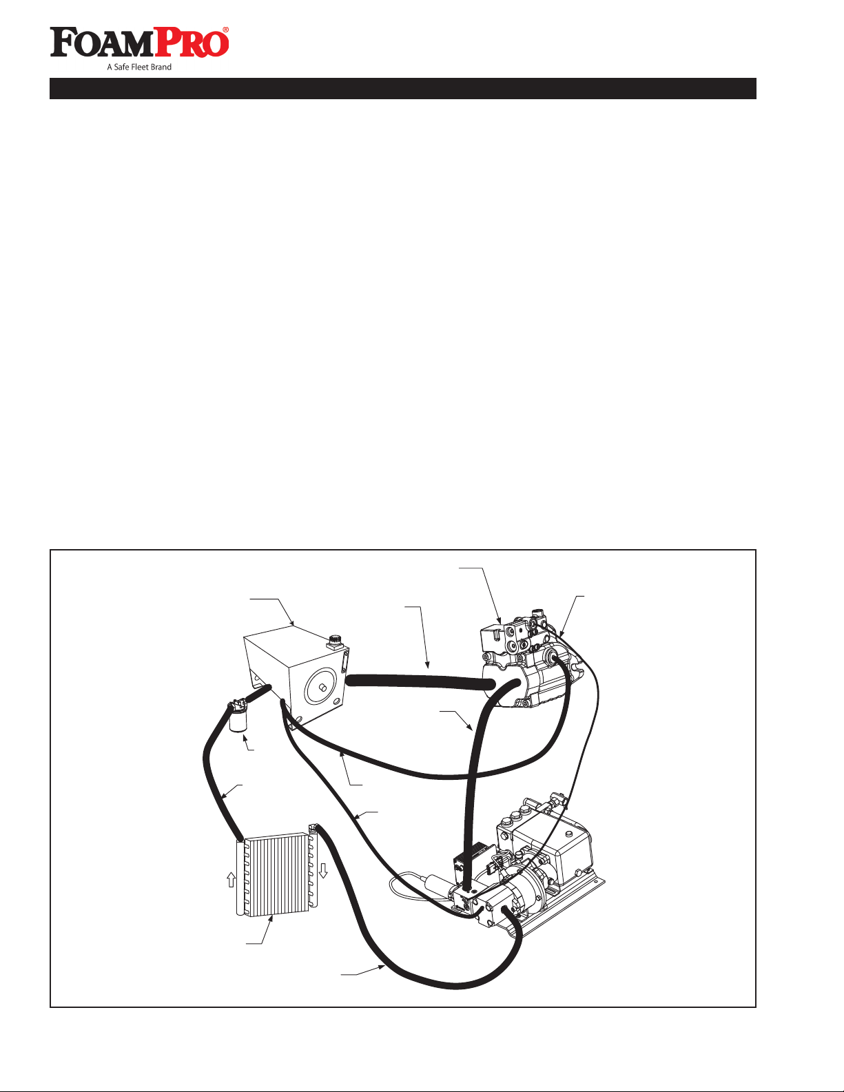
Figure 7-1 FoamPro 3012 Hydraulic System Diagram
Hydraulic Reservoir
System Filter
System Return
Hydraulic Oil Cooler
Hydraulic Motor Return
Hydraulic Pump
Suction Line
Hydraulic Pump
Discharge
Hydraulic Pump
Case Drain
Hydraulic
Motor
Case Drain
Hydraulic Pump
Load Sense Line
Load Sensing
Hydraulic Pump

15
Installation and Operation Manual
System 3012
Oil To
Reservoir
Oil From
Hydraulic
Motor
Thermostat
Control
Valve
Electric
Fan
Oil
Cooler
Hydraulic Reservoir
The hydraulic reservoir for the system is to conform
to the description in Section 4 and to all SAE and
DOT standards. See table in Section 15 for minimum
reservoir capacity for the unit being installed.
Hydraulic Oil Cooler
An oil cooler is required in the hydraulic system to
ensure proper oil temperature for optimum performance
and to avoid damage to the hydraulic components.
The actual cooler size required will depend on the
system requirements, the location of the cooler, and
the manufacturer of the cooler. Typical oil to air cooler
connections are shown in Figure 7-2. The cooling
requirements for the system being installed are listed in
the table in Section 15.
If an oil to water exchanger is used, proper
maintenance, mounting, and operating procedures must
be maintained. A method to circulate cool, fresh water
must be provided when the hydraulic pump is engaged.
A drain port must also be provided to prevent freezing
and to allow flushing.
Hydraulic Supply Pump Connections
After completion of the mounting of all hydraulic system
components, hose connections must be made. A table
in Section 15 shows the connector and minimum hose
sizes, and Figure 7-3 shows the connection ports to
use for the hydraulic supply pump. Always use the
uppermost case drain port available.
Load-Sense Pump Adjustment
The supplied load-sensing hydraulic pump does not
require any adjustment. The load-sensing compensator
is adjusted to give you maximum performance
throughout the entire operating range. The adjustment is
set with the hydraulic pump engaged and the FoamPro
3012 turned off. The hydraulic pressure will be 700 PSI
(48 BAR) and output flow rate will be 2 to 4 GPM (7.5 to
15.2 lpm). When the FoamPro 3012 system is engaged,
the load-sensing pump will supply the required hydraulic
flow and pressure to operate the system.
Hydraulic Motor Control Valve
The hydraulic motor control valve is adjusted at the
factory for optimum performance. The valve is not to be
removed or adjusted.
Figure 7-2 Oil Cooler Hose Connections
Figure 7-3
Hydraulic Supply Pump Connection Ports
Pressure
Compensator
Adjustment
Load Sense
Adjustment
Load Sense Port
#4 SAE O-ring Port
Inlet Port
#24 SAE
O-ring Port
Outlet Port
#16 SAE
O-ring Port
Case Drain
Port #10
SAE O-ring
Port

16
Installation and Operation Manual
Foam Tank
Water Tank
Water Pump
Water Flowmeter
Line Strainer
Foam Pump Assy.
Check Valve
Check Valve
(Optional)
Main Waterway
Check Valve
Flush Water
Shutoff Valve
Foam Tank
Shutoff Valve
Outboard
Pickup
Foam Injection Point
Single Discharge
Calibrate/Inject Valve
Foam Injection Check Valve
Hydraulic Motor
and Control Valve
Hydraulic Valve
Control Driver
Foam Tank
Low-Level
Sensor
Digital Display Controller
Multiple Discharge
with Manifold
Installation and Operation Manual
8 Plumbing Component Installation
Figure 8-1 provides recommended guidelines for the
installation of the system components that handle water,
foam concentrate and foam solution. Note that additional
options such as dual-tank system, multiple flowmeters,
etc., are covered by the individual manuals included
with those systems and consideration must be given to
potential interferences.
Figure 8-1 FoamPro 3012 System Piping
Water and Foam
Speed Sensor
CAUTION: Flexible hose connections are required
between the major FoamPro components and the
main water system. Do not hard plumb the system.
Foam Pump Discharge Relief Valve
The discharge relief valve on the outlet port of the
hydraulically-driven foam pump is preset at the factory
to ensure optimum performance of the FoamPro 3012
system.
Power & Ground
Connection Pin
A (Red) + 12 VDC
to + 27 VDC Pin B
(Black) Ground

17
Installation and Operation Manual
System 3012
Installation and Operation Manual
Calibrate/Inject Valve
The calibrate/inject valve is supplied in the fitting kit
and is to be positioned as shown in Figure 8-1 in the
system. This valve must be accessible by the pump
operator during normal operations. The valve is a 3-way
directional control valve that selects where the output of
the foam system will go. Check to make sure the valve
is installed properly. Look at the ports as you move the
selector handle. The flow should go from the center port
to each of the end ports.
The hoses to and from the valve should be 1/2"
(12.7 mm) inside diameter and be pressure rated to
400 PSI (28 BAR) minimum working pressure or the
maximum discharge pressure of the fire pump. Fittings
are to be 1/2" NPT and made of brass or stainless steel
with the same minimum pressure rating as the hoses.
The hose(s) from the calibrate side of the valve(s) may
have a lower pressure rating since it is used for system
calibration only and is always vented to the atmosphere.
If the system is to be tested to NFPA standards, the
calibrate side hoses must be rated to 400 PSI (28 BAR).
The hose(s) from this port must be long enough to reach
a container outside the apparatus and may be coiled for
storage when not in use.
Line Strainer
The line strainer provided with the FoamPro 3012
system is sized properly for most applications. See
Section 4 for further information. The appropriate
strainer is to be installed on the inlet side of the foam
pump. The hose from the foam tank should have
adequate wall stiffness to withstand the vacuum of the
foam pump while it is running without collapsing [23" Hg
(584 mm HG)].
CAUTION: If a pressurized water flush system
is incorporated, the plumbing exposed to this
pressure must be rated at or above the operating
pressure or a minimum of 400 PSI (28 BAR).
Main Waterway Flowmeters
The FoamPro 3012 system is designed to accept flow
reading signals from the FoamPro paddlewheel-style
flowmeter. Proper flowmeter sizing is critical to system
accuracy. Select a flowmeter size based on actual
flows required, not standard pipe sizes. Refer to the
installation drawing in Section 15 for proper flowmeter
sizing.
The flowmeters require that the amount of turbulence
in the pipe being monitored is as low as possible.
Excessive turbulence produces unstable and inaccurate
flow readings. The following installation guidelines will
help attain the best readings and maintain accuracy of
the FoamPro system.
1. A minimum 5 times the pipe diameter of straight
run pipe without any fittings is necessary upstream
of the flowmeter. 10 times is better. The longer the
straight run, the lower the turbulence. The following
are the recommended straight run lengths for given
pipe sizes:
Pipe Recommended
Size Straight Run Pipe
1-1/2"’ (38 mm) 7-1/2 to 15" (191 to 381 mm)
2" (50 mm) 10 to 20" (254 to 508 mm)
2-1/2" (64 mm) 12-1/2 to 25" (317 to 635 mm)
3" (76 mm) 15 to 30" (381 to 762 mm)
4" (100 mm) 20 to 40" (511 to 1016 mm)
2. The downstream plumbing of the flowmeter is not
as critical, but straight runs without fittings help
maintain accurate flow readings. A minimum 5 times
the pipe diameter is recommended.
3. Do not mount a flowmeter directly after an elbow
or valve. Valves create severe turbulence when
they are “gated down” as shown in Figure 8-2.
4. Try to mount the flowmeters in a position that is
accessible for routine inspection and maintenance.
The FoamPro paddlewheel-style flowmeter fittings
are specially designed tees that make inspection and
maintenance of the flow sensor easy. The threads of the
tees are available in NPT with grooved victaulic ends, or
BSP with grooved victaulic ends. In horizontal runs, the
tees should be mounted as close to upright as possible
within the range shown in Figure 8-3.
With the use of a MultiFlo interface, two to four
flowmeters may be monitored simultaneously. A single
injection point that will supply foam agent to all foam
discharge outlets is required. See Form 880 provided
with the MultiFlo System for further information
Injection Point
The position of the injection point MUST be in a place
that is common to all discharges which require foam
capability. This position may be before or after the main
water flowmeter, but not within the straight run distance
required for the flowmeter as previously described.
A separate injection point is not possible for each
discharge. If multiple flowmeters are used, the injection
point must be installed before the flowmeters at the inlet
to their common manifold (See Figure 8-4).

18
Installation and Operation ManualInstallation and Operation Manual
Figure 8-2 Flowmeter Placement
Figure 8-3 Flowmeter Position Range
NOTE: Most foam concentrates by nature mix with
water very quickly, so each discharge from a manifold
will receive equal amounts of foam concentrate if the
manifold is properly designed and installed. A static
mixer or special mixing considerations may need to
be designed into the system, especially when using
thicker foam concentrates and those that may not
readily mix with water.
Foam Concentrate Check Valves
Check valves are provided to prevent foam concentrate
flow from the concentrate tank through the injection
point and into the main waterway when the system is
not in use. This is a NFPA requirement. See Figure
8-1 for component placement. The concentrate check
valves have a minimum cracking pressure of 12 PSI
(0.8 BAR) and are pressure rated to 400 PSI (28 BAR)
minimum working pressure. It is a good idea to inject
foam concentrate at a horizontal or higher angle to allow
water and debris in the water line to drain away from the
check valve(s) as shown in Figure 8-5. This will avoid
sediment deposits or formation of an ice plug in cold
weather applications.
Main Waterway Check Valves
A check valve positioned in the main waterway prior to
the injection point must be installed. This will prevent
foam solution in the waterway from entering the pump,
the main water tank, and other clean water suction
connections as shown in Figure 8-6.
CAUTION: The check valve is not to be used as a
substitute for proper flushing of apparatus lines
after usage.
Flushing System
Depending on the corrosiveness of the foam
concentrates used, or when changing foam concentrate
types or manufacturers, a flushing system must be
installed. Generally all Class B foam concentrates must
be flushed from the system after usage. Most Class A
foam concentrates are less corrosive and do not require
flushing after each usage. See Figure 8-7 for a typical
flushing system plumbing schematic.
Figure 8-4 Injector Fitting Placement
for Multiple Discharge
Figure 8-5 Foam Injector Position
DO
DON’T
Injector Above
Horizontal Plane
Injector Below
Horizontal Plane
Injection
Point

19
Installation and Operation Manual
System 3012
Flushing Foam Pumps
When returning the apparatus to ready condition after
foam operations, the FoamPro foam pumps should be
flushed. The following procedures can be used to flush
the foam pumps. Refer to Figure 8-7 and do the following:
1. Energize apparatus and establish water flow
through foam solution discharge.
2. Close foam concentrate tank shut-off valve and
open flush water supply valve.
3. Energize FoamPro 3012 and allow electric motor
driven foam pump to run until discharge is clear.
4. Shut off FoamPro 3012 system by depressing the
FOAM button on the Digital Display Control Module.
Close flushing water supply valve.
5. Close foam solution discharge and shut
down apparatus.
6. Open foam concentrate tank shut-off valve.
7. Perform required maintenance checks on the
FoamPro 3012.
Figure 8-6
Recommended Pump Installation
Main Waterway
Check Valve
Injection Port
(Optional location
on other side of
Flowmeter)
Flowmeter
Drain Port
Minimum length of nipple for
2-1/2’’ pipe is 12-1/2’’ (318 mm).
Refer to Table on Page 17 for
recommended nipple lengths for
different pipe sizes.
Drain Lines
On apparatus with multiple drain lines, the drains from
the foam solution discharge line should not be piped
into a multi-drain system before the check valves. The
standard multi-drain system from most manufacturers
will allow cross talk between the drain lines and the
apparatus water tank, resulting in contamination of
the water tank with foam. A separate drain system
should be provided for the foam solution piping to
prevent contamination of the water tank and fire pump.
Figure 8-7
Foam Concentrate Flushing System Diagram
From
Fire
Pump
From Foam
Tank
Check
Valve
Flush Water
Shutoff Valve
Swing Check
Valve
Appropriate ID
Hose
Foam Strainer
Mounted On Foam
Pump Inlet

20
Installation and Operation Manual
Outboard Pickup
An outboard pickup may be adapted to the foam pump
inlet. The pickup should be positioned between the foam
tank shutoff valve and the foam inlet line strainer. A tee
the same size as the tank to pump line, may be placed
in the suction line with the side leg of the tee going to
the outboard pickup shutoff valve at the panel. A sealed
quick connect-type fitting may be mounted to the panel
for easy access. The outboard pickup line should not
exceed 10 feet and the same line size and specifications
as the tank to pump line should be utilized. The shutoff
valves must be full-ported valves and be air tight.
A switch must be provided to disengage the low-level
sensor when using the outboard pickup. This switch
may be a separate panel-mount or one that is tied into
the pickup valve actuator.
NOTE: The tank shutoff valve must be closed before
opening the outboard valve when switching to
the off-board pickup. The off-board pickup valve
must be closed before opening the tank valve when
switching to the foam tank operation.
Figure 8-8
Outboard Pickup Diagram
Strainer
Outboard
Pickup Line
Full-Ported
Shutoff
Valve
Full-Ported
Shutoff Valve
Switch to disconnect
Low-Level Sensor
when in Off-board
Operation
Foam
Tank
Driver
Box
Foam
Pump
Assy.
Other manuals for 3012
1
Table of contents
Other FoamPRO Measuring Instrument manuals


Popular Measuring Instrument manuals by other brands


PCB Piezotronics
PCB Piezotronics IMI SENSORS 628F61 Installation and operating manual

Grundfos
Grundfos DIT-M Installation and operating instructions

Circutor
Circutor QNA 412 user manual

Seiwa
Seiwa SW RP05 operating instructions

BAFANG
BAFANG DP C171.CAN user manual

Honeywell
Honeywell Chadwick-Helmuth 8500C Maintenance manual