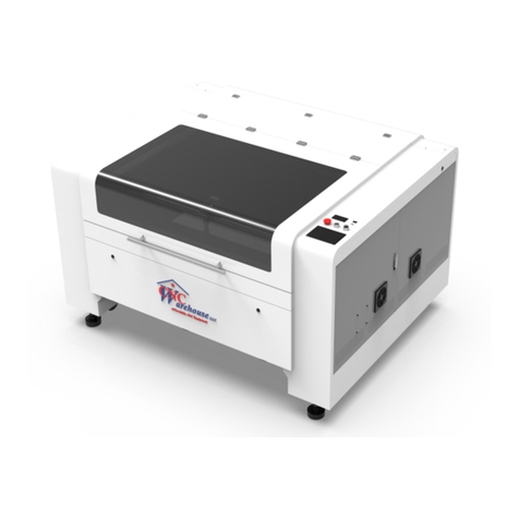
ECD WaveRIDER Series Installation manual

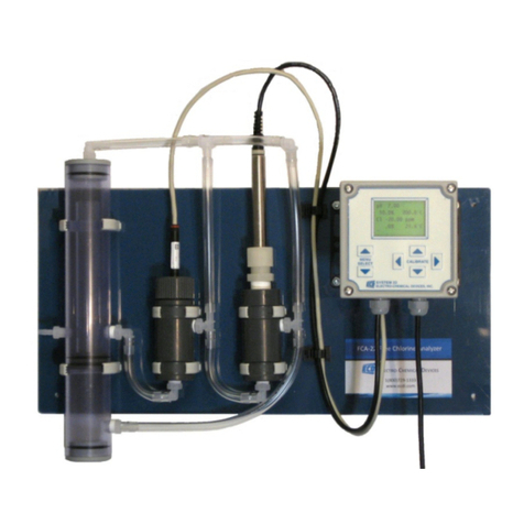
WaveRIDER
Hardware & Software Users Guide
WaveRIDER
Wave Solder Machine Analyzer
A36-9283-00 Rev 2.1

Copyright © 1996-2008 ECD. All Rights Reserved, Printed in U.S.A. Foreign and U.S. Products of ECD. are covered by Foreign and
U.S. patents or patents pending. No part of this Publication may be translated and/or reproduced or stored in a data retrieval system, or
transmitted in any form or by any means without the express written permission of ECD Information in this publication supersedes all
previously published material. Specification and price change privileges reserved.
The trapezoidal ECD logo M.O.L.E.(Multichannel Occurrent Logger Evaluator) and WaveRIDEare registered trademarks of
ECD Windowsis a registered trademark of Microsoft Corporation.
The WaveRIDER product is covered by U.S. Patent No. 5767424
SINCE 1964
ECD
4287-B S.E. International Way
Milwaukie, Oregon 97222-8825
Telephone: (800) 323-4548
(503) 659-6100
FAX: (503) 659-4422
Technical Support: (800) 323-4548
Internet: http://www.ecd.com

WaveRIDERi
WaveRIDERUsers Guide
TABLE OF CONTENTS
Introduction .................................................................................................................. vi
yTerms used in this Manual.....................................................................................vii
yFonts Used in this Manual.....................................................................................viii
yComputer Hardware Requirements.......................................................................viii
Operators Safety Information...................................................................................... ix
1.0 System Description................................................................................................. 1
1.1 Rider Description ................................................................................................. 2
1.2 Coupon Description .............................................................................................4
1.3 Software Description............................................................................................ 5
1.3.1 WR SPC Workbook Features......................................................................5
1.4 Standard WR SPC Worksheet functions..............................................................7
1.4.1 Worksheet tabs............................................................................................7
1.4.2 Selecting Worksheets.................................................................................. 7
1.4.3 Split-bar....................................................................................................... 7
1.4.4 Worksheet Tab Scroll Arrows......................................................................7
1.4.5 Scrollbars..................................................................................................... 8
2.0 Setup ........................................................................................................................ 9
2.1 Charging the Power Pack Battery........................................................................9
2.2 Software Installation...........................................................................................11
2.2.1 Starting the Software.................................................................................11
2.3 Communications Setup...................................................................................... 12
2.4 M.O.L.E. Installation........................................................................................... 16
3.0 Operation ............................................................................................................... 17
3.1 Data Collection................................................................................................... 17
3.2 Transferring Data...............................................................................................22
3.3 Expert Matrix...................................................................................................... 23
3.4 Cleaning the Rider............................................................................................. 27
3.5 Storing the RIDER ............................................................................................. 28

iiWaveRIDER
4.0 Worksheet Descriptions ....................................................................................... 29
4.1 The Welcome Worksheet...................................................................................29
4.1.1 Welcome Worksheet Menus and Toolbar.................................................. 30
4.1.2 Company/Report Name............................................................................. 31
4.2 WaveRIDER Data Worksheet............................................................................ 32
4.2.1 WaveRIDER Data Worksheet Menus and Toolbar Buttons....................... 33
4.2.2 Interpreting the WaveRIDER Data Sheet .................................................. 34
4.2.3 Data Coloring and LSL / USL .................................................................... 35
4.3 Spreadsheet Worksheet ....................................................................................36
4.3.1 Spreadsheet Menus and Toolbar Buttons ................................................. 37
4.3.2 Parameter Groups..................................................................................... 38
4.3.3 Parameter Labels...................................................................................... 40
4.3.4 Parameter Units......................................................................................... 40
4.3.5 Data Run Rows ......................................................................................... 41
4.3.6 Selected Run............................................................................................. 41
4.3.7 Filters......................................................................................................... 42
4.3.8 Statistics.................................................................................................... 45
4.4 Profile Worksheet...............................................................................................46
4.4.1 Profile Menus and Toolbar Buttons ...........................................................47
4.4.2 M.O.L.E. Status......................................................................................... 48
4.4.3 Tool Status Box......................................................................................... 49
4.4.4 Magnify Map..............................................................................................50
4.4.5 The Data Table.......................................................................................... 51
4.4.6 Sensor Locations....................................................................................... 56
4.4.7 Channel Check Boxes............................................................................... 57
4.4.8 Status Bar.................................................................................................. 58
4.4.9 Data Tabs.................................................................................................. 60
4.4.10 The Data Graph....................................................................................... 68
4.5 Administration Worksheet..................................................................................76
4.5.1 Administration Menus and Toolbar Buttons...............................................77
4.5.2 Spreadsheet Parameters........................................................................... 78
4.5.3 Parameter check boxes............................................................................. 78
4.5.4 Specification and Control Limit Cells ......................................................... 79
4.5.5 SPC Sheet Boxes...................................................................................... 83
4.6 Guide Worksheet............................................................................................... 88
4.7 SPC Worksheet ................................................................................................. 89
4.7.1 Menus & Toolbar....................................................................................... 90
4.7.2 X-Bar Chart................................................................................................ 91
4.7.3 R Chart...................................................................................................... 92
4.7.4 Statistics Box............................................................................................. 93
4.7.5 Renaming SPC Worksheets......................................................................94

WaveRIDERiii
5.0 Menu and Tool Commands .................................................................................. 95
5.1 File Menu...........................................................................................................95
5.1.1 New Workbook.......................................................................................... 95
5.1.2 Open Workbook......................................................................................... 97
5.1.3 Close Workbook........................................................................................ 97
5.1.4 Import ........................................................................................................ 98
5.1.5 Save Workbook......................................................................................... 99
5.1.6 Save Workbook As.................................................................................... 99
5.1.7 Save As Text........................................................................................... 100
5.1.8 Save as Text Archive............................................................................... 100
5.1.9 Load Text Archive.................................................................................... 101
5.1.10 Configuration ......................................................................................... 102
5.1.11 Preferences........................................................................................... 103
5.1.12 Page Setup............................................................................................ 111
5.1.13 Print Options.......................................................................................... 112
5.1.14 Page Header / Footer............................................................................ 113
5.1.15 Print Preview ......................................................................................... 114
5.1.16 Print....................................................................................................... 115
5.1.17 Report Setup ......................................................................................... 116
5.1.18 Print Report ........................................................................................... 116
5.1.19 Send to Mail Recipients......................................................................... 117
5.1.20 Recent Files 1, 2, 3, etc......................................................................... 118
5.1.21 Exit......................................................................................................... 118
5.1.22 Language............................................................................................... 118
5.2 Edit Menu.........................................................................................................119
5.2.1 Undo........................................................................................................119
5.2.2 Redo........................................................................................................119
5.2.3 Copy........................................................................................................119
5.2.4 Paste ....................................................................................................... 119
5.2.5 Remove Row........................................................................................... 120
5.2.6 Hide Row................................................................................................. 120
5.3 View Menu.......................................................................................................121
5.3.1 Zoom In ................................................................................................... 121
5.3.2 Zoom Out................................................................................................. 121
5.3.3 100% ....................................................................................................... 121
5.3.4 Data Table Tabs...................................................................................... 121
5.4 Format Menu.................................................................................................... 122
5.4.1 Bold ......................................................................................................... 122
5.4.2 Italic.........................................................................................................122
5.4.3 Underline................................................................................................. 122
5.4.4 Alignment (Left, Center, Right)................................................................ 122
5.5 Window Menu.................................................................................................. 123
5.5.1 Cascade .................................................................................................. 123
5.5.2 Tile...........................................................................................................124
5.5.3 Open File................................................................................................. 124

ivWaveRIDER
5.6 WaveRIDER Menu........................................................................................... 125
5.6.1 Configuration Wizard............................................................................... 125
5.6.2 Set M.O.L.E. Clock.................................................................................. 127
5.6.3 WaveRIDER Settings .............................................................................. 128
5.6.4 Read WaveRIDER Data.......................................................................... 129
5.7 Profile Menu.....................................................................................................130
5.7.1 Part.......................................................................................................... 130
5.7.2 Process.................................................................................................... 131
5.7.3 Scaling.....................................................................................................132
5.7.4 X-Axis Units............................................................................................. 133
5.7.5 Temp Ref Lines (Temperature Reference Lines) .................................... 134
5.7.6 Profile Colors........................................................................................... 135
5.8 Tools Menu......................................................................................................136
5.8.1 Magnify Tool............................................................................................ 136
5.8.2 Slope Tool ............................................................................................... 138
5.8.3 Peak Difference Tool............................................................................... 140
5.8.4 Overlay Tool............................................................................................ 141
5.8.5 3-D View.................................................................................................. 143
5.8.6 Measure Tool........................................................................................... 145
5.8.7 Notes Tool............................................................................................... 146
5.8.8 Erase Object(s)........................................................................................ 147
5.8.9 Erase All.................................................................................................. 147
5.9 Navigate Menu................................................................................................. 148
5.10 Help Menu...................................................................................................... 149
5.10.1 Help....................................................................................................... 149
5.10.2 ECD on the Web.................................................................................... 149
5.10.3 About WaveRIDER................................................................................ 149
6.0 Service and Calibration ...................................................................................... 150
6.1 Service Troubleshooting .................................................................................. 150
6.1.1 RIDER Troubleshooting Steps................................................................. 151
6.2 RIDER Coupon Replacement.......................................................................... 152
6.3 Checking the Coupon Thermocouples............................................................. 153
6.4 How to Get Additional Help.............................................................................. 153

WaveRIDERv
APPENDIX A: Specifications.................................................................................... 154
APPENDIX B: Statistical Process Control (SPC) Background Information ......... 155
APPENDIX C: Measurement Definitions.................................................................. 161
APPENDIX D: WR SPC Parameter Definitions........................................................ 168
APPENDIX E: WaveRIDER Accuracy and the Influencing Factors....................... 181
APPENDIX F: Pull-Down Menus & Toolbar Buttons............................................... 188
APPENDIX G: WaveRIDER Accessories ................................................................. 191

viWaveRIDER
Introduction
This User’s Guide explains how to use ECD’s (Electronic Controls Design Inc.)
WaveRIDER Wave Solder machine analyzer.
You do not need to be a computer expert to use this manual or the WaveRIDER
software.
The manual assumes you are familiar with Microsoft Windows.
The hardware portions of this manual are written to reflect SuperM.O.L.E. Gold
firmware versions 9.08 and higher. The software portions reflect versions 5.22
and higher.

WaveRIDERvii
yTerms used in this Manual
ECD. introduced the original M.O.L.E. (Multichannel Occurrent Logger Evaluator) in
1986. Over the years ECD has produced several models of the M.O.L.E. for use in a
wide variety of applications. In this manual, we may refer to the SuperM.O.L.E. Gold
data recording device as the M.O.L.E..
Informs the user that the note includes important information.
Informs the user that the note includes a handy tip.
The following statements describe special terms that will be used in this manual.
Hardware Terms:
Informs the user that the note identifies conditions or practices that
could result in damage to the equipment.
Informs the user that the note identifies conditions or practices that
could result in personal injury or damage to property other than the
equipment.
WARNING – Surfaces may be Hot!
SuperM.O.L.E. Gold, may be referred as the M.O.L.E..
WaveRIDER Ready refers to the M.O.L.E. being configured to collect wave solder
data when used with the WaveRIDER kit.
Thermocouple, may be referred to as T/C.
Software Terms:
WaveRIDER SPC software may be referred to as WR SPC.
Workbook, contains all of the worksheets and the uploaded data set saved with file
extension (.MWR).
Worksheet, the individual pages or sheets in the workbook file.
Data Set, multiple data runs uploaded into the workbook file.
Data Run / Experiment, the data uploaded from the M.O.L.E..

viiiWaveRIDER
yFonts Used in this Manual
This manual uses a special font to indicate terms or words that can be found directly on
the PC display.
For Example:Select the Open Workbook command from the File menu to open a new
workbook file. This font indicates the words Open Workbook and File are actually found
in the PC display.
yComputer Hardware Requirements
CPU, RAM, Hardware: 300mhz processor or equivalent
128 megabytes of RAM (minimum).
50 megabytes of free disk space.
Operating System: Windows XP & 2000.
Disk Drive: CD Rom drive.
Mouse: Windows compatible mouse.
Communication Port: Serial Port, USB (with port replicator).
Video: Color VGA or better video card and appropriate video
monitor. (SVGA is highly recommended)
It is recommended that the minimum computer display area be set to 800 x 600.
For best performance set the display to 1024 X 768 (Refer to your Microsoft
Windowsdocumentation for details).
Printer: Color printer is recommended.

WaveRIDERix
Operators Safety Information
The safety information in this summary is for the benefit of operating personnel.
Warnings and Cautions will also be found throughout the manual where they apply.
Hardware changes or modifications to the components are not expressly
approved by ECD could void the product’s warranty.
For protection of the kit components, observe the following:
Do not subject the components to sharp impacts.
Do not expose the components to corrosive environments.
Do not expose the RIDER, above the specified maximum temperature.
The warranty will not cover damage caused by neglect or abuse of this product.
To maintain the safety features incorporated in this product, operation must be in
strict compliance with the requirements specified herein.

WaveRIDER1
1.0 System Description
The main WaveRIDER hardware component is called the RIDER. The RIDER is a
solder machine data collection pallet with ECD’s SuperM.O.L.E. Gold at the heart of it.
When the M.O.L.E. is connected to the RIDER it takes on a special WaveRIDER
configuration for proper data interpretation. While riding on the solder machine,
conveyor data from the solder machine is collected by the RIDER and stored in the
internal memory of the M.O.L.E. After the RIDER has completed the data collection, it is
then connected to a PC and the data is uploaded into the WR SPC software for
analysis.
DISTANCE/TIME SENSORS
ABC
1
2
3
4
5
6
M.O.L.E.
PC
COUPON TEMP.
SENSORS
RIDER
Figure 1- 1: System Block Diagram

2WaveRIDER
1.1 Rider Description
This section covers brief descriptions for the external and internal features of
WaveRIDER.
External features:
Barrier box: This is the thermal protective barrier for the M.O.L.E..
Barrier locking latch: This latch secures the cover of the barrier to prevent it
from opening.
Coupon: Sensors that record temperature data from the solder machine. (Refer
to section 1.2 Coupon Description for more information).
Figure 1- 2: WaveRIDER
COVER LATCH
COUPON
BARRIER BOX

WaveRIDER3
Internal Features:
Connector bridge: This is where the M.O.L.E. plugs into the WaveRIDER so it
can collect data from the RIDER sensors.
Extractor handle: This handle assists in the removal of the M.O.L.E..
Configuration plug: This plug configures the M.O.L.E. to operate in
“WaveRIDER” mode.
Figure 1- 3: WaveRIDER Internal Features
CONNECTOR BRIDGE
CONFIGURATION PLUG
EXTRACTOR HANDLE

4WaveRIDER
1.2 Coupon Description
Temperature data about a solder machine is taken from three type "K" thermocouples
(T/C) attached to the Coupon. Their purpose is to sense the impact of a solder machine
setup on circuit board "like" material, as opposed to the RIDER pallet material.
Figure 1- 4: Coupon Description
The "Bottom Foil" T/C is inserted into the coupon as close to the bottom surface as
possible without breaking through. The "Solder" T/C is exposed below the bottom
surface of the coupon so it will contact the solder. The "Top Foil" T/C is inserted into the
coupon near the top surface.
Figure 1- 5: Coupon Cross section
“BOTTOM FOIL” T/C
“SOLDER” T/C
“TOP FOIL” T/C
COUPON
THREE TYPE “K”
THERMOCOUPLES
“BOTTOM FOIL”
THERMOCOUPLE “SOLDER”
THERMOCOUPLE “TOP FOIL”
THERMOCOUPLE

WaveRIDER5
1.3 Software Description
This section presents an overview of a workbook management window. When the
software is started, it will automatically load the previously saved workbook file.
The first time the software is started a sample file (i.e. WRSample.mwr) will be
opened for users to familiarize themselves with the program. It is recommended
when the user starts collecting process data, a new or existing workbook should
be used.
1.3.1 WR SPC Workbook Features
The workbook has several features as described in the following section.
Figure 1- 6: Workbook Features
TOOLBAR
MENUS
SPLIT BAR
TITLE BAR
WORKSHEET TAB
SCROLL ARROWS
STATUS BAR
VERTICAL SCROLL BAR
HORIZONTAL
SCROLL BAR
WORKSHEET TABS

6WaveRIDER
Title Bar: This bar contains the program name, version, and the active workbook
file name.
Menus: These menus contain the commands and tools for each worksheet.
Each worksheet may contain different commands that supply specific support for
each worksheet. Individual worksheet menus are described in detail in their
specified sections of this manual.
Toolbar: The Toolbar has buttons to serve as shortcuts to the menu commands.
Individual worksheet toolbar buttons are described in detail in their specified
sections of this manual. Each worksheet may have different items on the toolbar
because of the different features offered by each worksheet.
Worksheet Tabs: These tabs are used to gain access to each worksheet.
Tab Scroll Arrows: These arrows are used to view other worksheet tabs if the
Horizontal scroll bar is covering them.
Split-bar: This bar slides the Horizontal Scroll bar to the left or right so all or part
of the worksheet tabs can be viewed.
Status Bar: This bar on the bottom of the worksheet display, shows the available
Help information, mouse pointer X-Y position, current date and time.
Horizontal Scroll Bar: This bar scrolls the worksheet display horizontally left
and right.
Vertical Scroll Bar: This bar scrolls the worksheet display vertically up and
down.

WaveRIDER7
1.4 Standard WR SPC Worksheet functions
1.4.1 Worksheet tabs
There are six standard worksheets and up to nine optional SPC sheets. These tabs are
located on the bottom left of the display.
Figure 1- 7: Worksheet Tabs
1.4.2 Selecting Worksheets
To a view worksheet, use the mouse pointer to click on a worksheet tab. The worksheet
tab will then become highlighted, and the worksheet will now be visible.
The keyboard does not allow access to the worksheets. The only way to select
the worksheet is by using the mouse pointer.
Figure 1- 8: Selecting a Worksheet
1.4.3 Split-bar
The Split-bar on the tab bar lets the user slide the Horizontal scroll bar to the left or
right, so all of the worksheet tabs can be viewed. This feature is located on the left edge
of the Horizontal scroll bar.
1.4.4 Worksheet Tab Scroll Arrows
Worksheet tabs may be hidden behind the horizontal scroll bar. To view them, the user
can either use the Tab Scroll Arrows located on the left of the worksheet tabs, or use
the Split-bar.

8WaveRIDER
1.4.5 Scrollbars
The worksheets have both Horizontal and Vertical screen scroll bars so the non-visible
areas of the worksheet can be scrolled into view. The Horizontal scroll bar is located in
the lower right corner and can be scrolled left or right by pressing the left or right arrows
located on each end of the scroll bar. The user may also scroll the display by sliding the
center scroll bar left or right. The Vertical scroll bar located on the right side of the
screen has the same features as the Horizontal scrollbar except it scrolls the worksheet
display up and down.
Figure 1- 9: Worksheet Options
It is recommended that the minimum PC display area be set to 800 x 600. For best
performance set the display to 1024 X 768 (Refer to your MicrosoftWindows
documentation for details).
CLICK HERE TO SCROLL WORKSHEET TABS
CLICK AND DRAG TO VIEW
WORKSHEET TABS
CLICK TO
SINGLE STEP
WORKSHEET
VIEW LEFT OR
RIGHT
CLICK AND DRAG TO SLIDE
THE VIEW HORIZONTALLY

WaveRIDER9
2.0 Setup
This section provides the necessary information to setup M.O.L.E. components for data
collection.
2.1 Charging the Power Pack Battery
Because the M.O.L.E. is powered by a rechargeable Power Pack battery, it is important
that it is charged and operating properly prior to performing every experiment. A spare
Power Pack battery may be ordered so the one battery is charging while the other one
is being used.
Charging:
1) Remove the Power Pack battery by separating from the unit.
Figure 2- 1: Removing the Power Pack Battery
Table of contents
Other ECD Measuring Instrument manuals
