Audiovox Electronics GMRS1882 User manual

128-8333
1 of 30
Model:GMRS1882CH
CustomerService
1-800-290-6650
Released: Jan-28-08
Owner'sManual
GeneralMobile RadioService (GMRS)

128-8333
2 of 30
2
THISDEVICECOMPLIESWITHPART15OFTHEFCCRULES.
OPERATIONIS SUBJECT TO THE FOLLOWING TWO CONDITIONS:
(1)THISDEVICEDOESNOTCAUSEHARMFULINTERFERENCE,AND
(2)THIS DEVICE MUST ACCEPT ANY INTERFERENCE RECEIVED,
INCLUDINGINTERFERENCETHATMAYCAUSEUNDESIRED
OPERATION.

128-8333
3 of 30
CAUTION
SAFETY INFORMATION
Your wireless hand-held portable transceiver contains a low power
transmitter. When the PTT button is pushed (or the VOX mode is enabled)
itsends outradio frequency(RF) signals.The deviceis authorizedto operate
at a duty factor not to exceed 50%. In August 1996, the Federal
Communications Commissions (FCC) adopted RF exposure guidelines
with safety levels for hand-held wireless devices.
Important: To maintain compliance with the FCC' s RF exposure guidelines
hold the transmitter at least 1 inch (2.5 centimeters) from your
face and speak in a normal voice, with the antenna pointed up
and away. If you wear the handset on your body while using the
headset accessory, use only the Audiovox supplied carry clip
for this product and ensure that the antenna is at least 1 inch
(2.5 centimeters) from your body when transmitting. Use only
the supplied antenna. Do not use your transceiver with a
damaged antenna. Unauthorized antennas, modifications, or
attachments could damage the transmitter and may violate
FCC regulations.
Performance:
Your transceiver will only achieve its maximum operating range when
communicating with other transceivers across open and flat areas or
between elevated points. Normally occurring environmental factors such
as buildings, trees, terrain and weather, or interference from other radio or
electricalequipment,may haveadverseeffects onthe transceiver'seffective
range. These are not indicative of a fault condition.
Avoid placing the GMRS1882CH radio transceiver for prolonged periods of
time in direct sunlight or temperatures below -4°F (-20°C) or above
140°F (60°C).
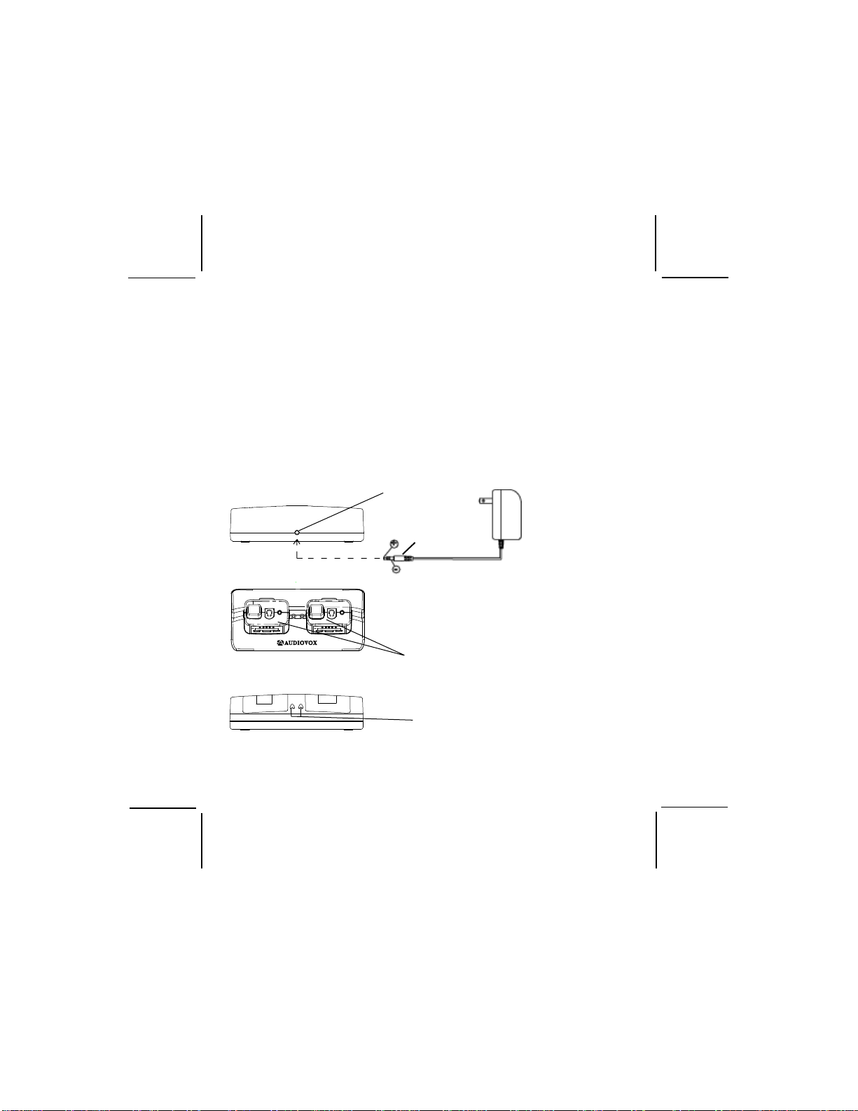
Place the rubber cover on jacks when not in use.
3

128-8333
4 of 30
WARNINGS:
Battery Care
Never attempt to charge alkaline or dry cell batteries, as batteries may
burst causing personal injury and damage to the product. If rechargeable
batteries are used, such as Nickel Metal Hydride (Ni-MH), use only the
supplied Audiovox-approved rechargeable batteries. Use of the Audiovox
charger (also supplied) with other brands of batteries is not recommended,
as battery charging times will vary with different brands. Refer to the
Manufacturer’s instructions for charging other brands of batteries.
Battery Disposal
In general, if handled improperly, batteries pose a risk of fire or burns. Do
not disassemble, crush, puncture, short external contacts, or dispose of
the batteries in fire or water. Dispose of the batteries in a environmentally
safe manner and recycle whenever possible.
FCC WARNING
Replacement or substitution of transistors, diodes or other parts of a unique
nature, with parts other than those recommended by the manufacturer,
may cause a violation of the technical regulations of Part 15 of FCC Rules.
GMRSLICENSE:
USE OF THIS RADIO WITHINTHE UNITED STATES REQUIRESAN FCC
GMRSLICENSE. AN INDIVIDUAL18YEARS OFAGEOR OLDER,WHOIS
NOTAREPRESENTATAIVE OFAFOREIGNGOVERNMENT,IS ELIGIBLE
TOAPPLYFORAGMRSSYSTEMLICENSE. YOUWILLNEEDTWOFORMS
FROMTHE FCC:FCC FORM159,ANDFCCFORM 605(MAIN FORMAND
SCHEDULE F). YOU CAN FIND THE FORMS ONLINE AT:
HTTP://WWW.FCC.GOV/FORMPAGE.HTML,ORCALL1-800-418-3676.
4

128-8333
5 of 30
5
1. BatteryDoor
2. Monitor/BacklightButton
3. DetachableCarryClip
4. Push-To-Talk(PTT)Button
5. Antenna
6. ExternalSpeaker(SPK)/Micro-
phone(MIC)/Charge(CHG)
Jack
7. Built-inSpeaker
8. LiquidCrystalDisplay(LCD)
Model GMRS1882CH (FCC License Required)
9. Built-inMicrophone
10. UpChannel/VolumeButton
11. DownChannel/Volume
Button
12. MODE/WeatherButton
13. PowerOn/Off&Scan
Button
14. VOXButton
15. White Flashlight LED
16. FlashlightEnableButton
17. BatteryCharging Contacts
1
2
3
4
5
8
11
912
6
14
10
13
73
(REF)
1
(REF)
17
16
15
18. CrankCharging Lever
18

128-8333
6 of 30
6
Model GMRS1882CH DISPLAY
1.Beep Tone Indicator: Icon appears when beep button confirmation
tone is selected; icon disappears when tone is off.
2.Key Lock Indicator: Icon appears when the keypad is locked. This
function disables keys such as channel up/down, SCAN and MODE.
3.Monitor Indicator: Icon appears when the Monitor (M) button is
pressed and the channel monitor function is activated.
4.Signal Strength Indicator: Icon appears when a signal is being
transmitted. The icon consists of five bars to indicate transmit signal
power level.
5.HI/LO Indicators: Power level indicator appears when the transmit
power is set to desired output power on the GMRS channels.
6.Large Segment Display: Indicates the channel number in use in
GMRS/FRS mode or WEATHER BAND mode.
7.Scan Indicator: This function allows the user to scan a channel (and
tone code, if present) every .5 second to search for a valid signal.
8.RogerBeep Tone On/Off Indicator: This icon appears when the
Roger Beep tone is on, and disappears when tone is not in use.
9.Battery Level Indicator: Icon indicates the battery charge level.
10.Signal Receive Indicator: RX icon appears when a signal is being
received.
1
2
3
4
5
6
7
8
9
10
12
13
14
11.Small Segment Display: Displays the CTCSS tone option for each
main channel from 01-38.
11

128-8333
7 of 30
7
13.Dual Watch Mode Indicator: Indicator appears when dual watch
mode is active.
14.Voice Activated Transmission (VOX) Indicator: This function
allows hands free conversation. The indicator appears when the
VOX mode is activated.
Equipment and Accessories Supplied
1. Radio (2) GMRS1882CH
2. Owner’s Manual 128-8333
3. Desktop Charger GMRS18DS
4. AC WallAdapter GMRS25AC
5. Rechargeable (NiMH) Batteries (8) GMRS6BAT
6. Detachable Carry Clip GMRS122BCLIP
Powering theTransceiver:
Your GMRS1882CH radio transceiver operates on four AAA Alkaline or
rechargeable batteries. Alkaline batteries will provide slightly better
performance than rechargeable batteries (supplied). Only Audiovox
approved rechargeable batteries should be recharged in the radio
transceiver using the charging accessories. This will ensure optimum
performance for the GMRS1882CH. Battery charging time is typically 6-7
hours for full charge, and 0.5-3 hours for fast charge (depending on existing
battery charge). (Refer to battery charging instructions later in this manual.)
Batteries may get warm during fast charge. Slow charging will automatically
occur after a quick charge of 75%, and may take up to 3-4 hours to achieve
an additional 20% charge. Batteries should not get warm during the slow
charge cycle. Use of theAudiovox charging equipment with other brands of
rechargeable batteries is not recommended as battery charging times will
vary. Refer to the manufacturer’s instructions for charging other brands of
batteries.
12. Weather Mode Indicator: Icon will be on steady when in the weather
band mode. When in the GMRS/FRS mode, the icon will blink when
the alert is active.

128-8333
8 of 30
8
Batteries
There are three methods of powering the GMRS1882CH:
1. Alkaline Batteries.
WARNING: Do not attempt to recharge Alkaline batteries.
2.AudiovoxRechargeableNi-MHBatteries-(RechargeableNi-MH
batteries and Charging Adapter included). Use only Audiovox
approved rechargeable batteries and charging equipment when
charging batteries internal to the unit.
NOTE: To extend battery life, avoid overcharging the batteries
3. Various Brands of Rechargeable Batteries - Use of the Audiovox
charger with other brands of rechargeable batteries is not
recommended, as battery charging times will vary with different
brands of batteries. Refer to the manufacturer’s instructions for
charging other brands of batteries.
Installing the batteries:
Battery installation is made more convenient when the carry clip is
removed. To do this, release the spring latch securing the clip to radio
and slide the clip downward and away from the radio body.Using
forefinger, grasp the battery cover behind the embossed arrow and pull on
the cover to lift to open. Insert four AAA batteries (alternate positive
ends (+) toward the right side of the transceiver (starting top-to-bottom).
2.Usingforefinger,pullonbatterycover
at"arrow"markandthenlifttoopen.
Removecover.
3.InsertfourAAAbatteries(positive(+)end
towardright side begining at top and
alternatingpositiveterminalsas shown).
1.Using forefinger, pullon
charging leverat"PULL"
marktoflip.
RELEASE
BUTTON
CARRY
CLIP
BATTERY
COVER
CHARGING
LEVER
PULL

128-8333
9 of 30
9
The following guidelines will improve performance and provide longer
operating times for the GMRS1882CH:
1. Do not mix old and new batteries.
2. The use of alkaline-type batteries is recommended to provide the
longest operating time.
3. Do not mix alkaline, standard (carbon-zinc) or rechargeable
batteries.
4. If the unit is not to be used for an extended period of time, remove the
batteries. Old or leaking batteries can cause damage to the unit and
will void the warranty.
INPUT: 120VAC
OUTPUT: 12VDC
DESKTOP CHARGING STAND
PARTNUMBERGMRS18DS
CHARGING STAND
PWR JACK
ADAPTER
POWER
PLUG
GMRS RADIO
CHARGING
COMPARTMENTS(2)
CHARGINGCOMPARTMENT
LEDs:
RED----FAST CHARGING
OFF----SLOW CHARGING
NOTE:
Only
Audiovox
approvedrechargeable
batteries(P/NGMRS6BAT)
can be recharged in the
radio transceiver.
AC WALL ADAPTER/
CHARGING TRANSFORMER
MODEL:GMRS25AC

128-8333
10 of 30
10
GMRS1882CH OPERATION MODE
WEATHERBAND
Weather CHANNEL
SELECT
ROGER
BEEP
BUTTON
BEEP
DUAL
WATCH
VOXLEVEL
SELECT
CALL
SELECT
POWER
SELECT (GMRSChannels
Only)
GMRS/FRSBAND
CTCSS
SELECT
CHANNEL
SELECT
NOTE: 1. To switch between GMRS/FRS
and Weather Band modes,
press and hold the MODE/WB
button for 2 seconds. Refer to
the appropriate section of this
manual for detailed operating
instructions for each mode.
2.To enter the VOX mode, press
and hold the VOX button for 1
second.
WeatherALERT
On/Off
Controls:
LEDFlashlight Button(16)
Press this button on the right side of the Transceiver to light the white LED
(15) on top of the unit, thereby activating the built-in flashlight function.
Power On-Off/SCAN Button (13)
Press and hold the power on/off button ( ) for 2 seconds.You will hear
a dual beep to indicate the unit is on. Press the on/off button again for 2
seconds to turn the unit off. When the unit is on and the button is pres-
sed momentarily, the scan mode is enabled or disabled; when enabled,
the scan icon (SCAN) appears on the display.
Adjusting the Volume (10, 11)
With the unit powered on, press the Up Channel/Volume button ( ) to
increase volume and the Down Channel/Volume button ( ) to decrease

128-8333
11 of 30
11
volume. The display will indicate the current volume level between 0 and 7
by the small number in the icon ( UL5 ).
Monitor/Keylock Button (2)
This button is used to check activity on the current frequency before
transmitting. Check activity by pressing the Monitor (M) Button longer
than 2 seconds; the icon will apppear on the display and you will
hearstaticif frequency isclear.
Do not transmit if you hear conversation.
Hold down the Monitor Button again longer than 2 seconds and the
icon will disapppear from the display.
The monitor function will temporarily bypass the squelch setting and play
all signals on a given channel. This feature is useful when communicating
with other parties at extreme range.
By pressing the monitor button momentarily, the keylock icon ( ) will
appear to confirm that the MODE, SCAN and channel up/down button
functions have been disabled.
Push To Talk (PTT) Button (4)
Pressing and holding this button will allow you to speak to any transceiver
that is set to the same channel and privacy code setting as yours. Hold the
transceiver approximately 1 to 2 inches from your face as you speak into
the built in microphone (9). After you have finished speaking, release the
PTT Button to allow reception of incoming signals. It is not possible to
transmit and receive at the same time. The Transmit Signal Level indicator
( ) will display the relative strength of the transmitted signal. When
receiving an incoming signal, the RX icon will appear in the upper right
quadrant of the display. The PTT button can also be used as a two-way call
ringer. Pressing the button twice quickly will call another party on the same
channel.
Up Channel/Volume Button (10)
In the standby mode, pressing this button will increase the listening volume.
When in function edit mode this button will be used to adjust the unit’s
settings.

128-8333
12 of 30
12
Down Channel/Volume Button (11)
In the standby mode, pressing this button will decrease the listening
volume. When in function edit mode this button will be used to adjust the
unit’s settings.
MODE/WBButton(12)
This button is used to select the various feature settings in the GMRS/FRS
or scanner modes.Holding the MODE/WB button longer than 2 seconds
will toggle between the GMRS/FRS andweather band modes.
External Microphone (MIC)/Speaker (SPK)/(CHG) Jack (6)
This jack accepts the supplied Audiovox Earbud/microphone connector, or
the Charging Adapter. For the equipment and accessories supplied with
the GMRS1882CH, refer to Page 7 and/or visit the Audiovox web site at
www.audiovox.com.
VOX Button (14)
Press and hold this button for more than 1second to enable or disable
the VOX mode; the VOX icon will appear in the lower right corner of the
display when enabled.
Operating Modes and Features
GMRS Operation:
- From GMRS/FRS standby mode, press the ( ) button for about 2
seconds to turn on power.
- Press the MODE button so the Channel number flashes.
- Select the desired channel with the Up (10) and Down (11) Buttons.
When receiving a call, the RX icon appears to indicate the incoming
signal.
- Press and hold the PTT button (4) to transmit, then speak into the
microphone clearly and slowly.The Transmit Signal Level indicator
() will display the relative strength of the transmitted signal.
- Release PTT Button (4) to receive.
- Communication can only be accomplished when the channel and

128-8333
13 of 30
13
CTCSS tone frequency of at least two parties are the same.
- The CTCSS small segment display will appear next to the main
frequency channel on the display if the CTCSS tone frequency
function is enabled.
Channel Selection
In order to communicate with other GMRS units, both transmitting and
receiving party must be on the same frequency.The GMRS1882CH has 22
channels (frequencies) indicated by the large digits on the LCD display
panel. Channels 1 through 7 are the shared GMRS/FRS channels.
Channels 8-14 are FRS only channels, while channels 15-22 are assigned
GMRS only channels. If an FRS only channel (8-14) has been selected,
HI or LO the indicator will not be displayed on the LCD panel; otherwise,
for channels 1-7 (GMRS/FRS) and 15-22 (GMRS only), the HI or LO
indicator will be displayed. Communication with Audiovox FRS and
compatible units is possible on the shared and FRS only channels. Before
transmitting on the selected channel, press the Monitor (M) Button (2)
tocheck theactivityon thatchannel.If thereisactivityonthe selectedchannel,
change to another channel that is clear .
To change the channel:
- From GMRS/FRS standby mode, press the MODE button (12) once
or until the channel number flashes.
- Press the Up Button (10) briefly to move to the next higher main
channel number.
- Press the Down Button (11) briefly to move to the next lower main
channel number.
- Press the PTT button momentarily to confirm selection.
CTCSS Mode (Sub-Channel) Selection
The Coded Tone Controlled Squelch System (CTCSS) provides 38 Sub-Fre-
quencies.This feature allows you to utilize the coded squelch tones (01-38)
within a main channel, and enables you to communicate with another
party on the same main channel using the same subcode. (This filters out
unwanted transmissions without the same coded squelch tone). There

128-8333
14 of 30
14
are 38 CTCSS sub-channels for each main channel. Adifferent subcode
may be selected for each of the 22 channels.
To change the CTCSS sub-channel:
- From GMRS/FRS standby mode, press the MODE Button twice; a
flashing oF or sub-channel number is displayed. If oF is displayed,
press the Up or Down button to enable the CTCSS mode.
- Then press the Up or Down button to select the desired sub-channel
for use (01-38).
- Press the PTT button momentarily to confirm selection.
The CTCSS mode can be turned off by selecting the oF icon as the setting.
NOTE: To communicate with other GMRS/FRS units, they must be
switched to the same channel and CTCSS subcode. To commu-
nicate with other GMRS/FRS units that do not have subcodes,
switch your unit to the same channel with the subcode set to oF.
The CTCSS subcodes do not prevent others from hearing your
transmission. This will only allow you to ignore all traffic on a
given channel not using the same subcode.
Transmit Power Selection Mode
This feature permits selection of the transmitting power level to high
or low. When operating on FRS only channels (8-15), no power selec-
tion is possible or is displayed. Using low power, the unit will have a
lower transmit range, but battery life will be increased.
To access the transmitter power selection function:
- From GMRS/FRS standby mode (shared channels 1-7 or GMRS only
channel (15-22) selected), press the MODE Button three times until
the power HI or Lo indication appears with a flashing Po indication on
the display .
- Press the Up or Down button to toggle between the High, Middle and
Low selections.
- Press the PTT button momentarily to confirm selection.

128-8333
15 of 30
15
VOX Sensitivity Level Selection
This selection enables you to set the sensitivity level to compensate for
ambient noise in your immediate area. A VOX sensitivity of 3 is the most
sensitive, and should be used in a relatively quiet surrounding. A VOX
sensitivity of 1 is the least sensitive and should be used in a noisy sur-
rounding.
To set the VOX sensitivity level:
- Press the MODE button 4 times (3 times for FRS) until the VOX icon
appears on the display accompanied by the flashing VOX icon and
the numeral 1,2or 3.
- Press the Up or Down button to select the 1-3 VOX level sensitivity.
- Press the PTT button momentarily to confirm the VOX selection.
- The VOX icon will disappear from the display unless VOX mode is
enabled.
Dual Watch Mode
This feature allows you to monitor two channels at the same time. While in
dual watch mode, the unit will continuously monitor both the primary and
dual watch channel. Received signals will be played for 5 seconds, then
the unit will resume scanning the two channels. Pressing the PTT button
during a received transmission will set the unit to transmit on the same
channel. Pressing the PTT button when no signal is received will set the
unit to transmit on the primary channel.
To set the Dual Watch Mode:
- From GMRS/FRS standby mode, press the MODE button 5 times (4
times for FRS); DW appears flashing on the display. If the dual watch
mode is off, the oF icon will also appear flashing.
- To enable the dual watch mode, press the Up or Down button; the dual
watch channel number will flash and start to increase or decrease as
the Up or Down button is pressed.
- To select a subcode for the dual watch channel, press the MODE
button while the selected dual watch channel is flashing. Then use the
Up and Down buttons to select the desired CTCSS subcode. Press

128-8333
16 of 30
16
the PTT button momentarily to confirm selection of the dual
watch channel. The display will now alternate between the primary
channel and the dual watch channel just selected.
NOTE: Pressing the PTT button during dual watch mode will trans-
mit on the primary channel and suspend dual watch opera-
tion for 5 seconds. Dual watch mode will then resume.
- Momentarily press the SCAN (s) button to exit the dual watch mode.
Key Tone
This feature allows the transceiver to sound a confirmation tone whenever
thefollowing keysare pressed:Monitor (M)Button,Up/Down Buttons,MODE
Button or SCAN Button.
To turn the key tones on or off:
- From GMRS/FRS standby mode, press the MODE Button 6 times (5
times for FRS) until the Bell ( ) icon flashes, and on or oFF appears
on the display.
- Press the Up or Down Button to toggle the key tone feature On or Off.
- Press the PTT button momentarily to confirm selection.
When the key tone feature is on, the Bell icon appears steady on the
display, and the beep tones sound in response to button activation.
Roger Beep Tone
The Roger Beep is a tone which is automatically transmitted whenever the
PTT button is released. This tone alerts the receiving party that the trans-
mission has been terminated intentionally.
To enable and disable the Roger Beep tone:
- From GMRS/FRS standby mode, press the MODE Button 7 times (6
times for FRS) until the flashing Roger Beep icon ( ) and on or oF
appears on the display.
- Press the Up or Down button to select the tone on or off as desired.
- When enabled, the tone icon ( ) appears steady on the display.
- Press the PTT button momentarily to confirm selection.

128-8333
17 of 30
17
Call Ringer Selection Mode
The transceiver provides 10 user-selectable call ringer melodies to alert
you to an incoming call.
To select your favorite call ringer melody:
- From GMRS/FRS standby mode, press the MODE Button 8 times (7
times for FRS). CA will appear on the display, together with a flashing
number between 1and 10, and an appropriate call ring.
- Press the Up or Down Button to preview and hear the 10 available call
melodies.
- Press the PTT button momentarily to confirm selection.
Channel Scan Operation
This feature allows you to monitor all channels automatically for valid
signals. While scanning, you can transmit and receive. When a signal is
received, the scan is interrupted and will return to scan mode 5 seconds
after reception is terminated.
NOTE: While the scan function is active, the MODE/WB button will be
inoperative. The scan mode will reduce the overall battery life
since the battery save function is overridden.
To enable the channel scan mode:
- From GMRS/FRS standby mode, momentarily press the Power (S)
Button; (SCAN) will appear on the LCD display.
- The radio will display each channel (1-22) in ascending order as the
scan mode operates to find an active main channel.
- If the unit doesn’t find any signals and you want to transmit, press
the PTT button to return to home channel operation. The transceiver
will automatically resume scanning approximately 5 seconds after
the communication is completed.
- If there is no activity and you want to leave the scan mode, press the
Sbutton momentarily and the unit will return to normal operation;
the SCAN icon will disappear from the LCD display.

128-8333
18 of 30
18
Auto Key Lock Selection Mode
This feature prevents accidental channel change to the preferred settings
of the unit. The Auto Key Lock function temporarily disables the MODE, Up/
Down and SCAN Buttons.
To access the Auto Key Lock selection menu:
-From GMRS/FRS standby mode, momentarily press the Monitor (M)
button to enable the Auto Key lock function; the unit will beep once
and the lock ( ) icon appears on the display.
- The Power, PTT, and Monitor Buttons are not effected.
- To unlock the Auto Key function, momintarily press the Monitor (M)
button; the unit beeps once and the lock icon ( ) disappears from
the display.
NOTE: If the unit is turned off while Key Lock is on, the Key Lock
mode will still be in effect when the unit is again turned on.
VOX Enable Operation
This option enables you to have hands-free conversation. Your voice or
nearby sound is detected and the radio transmits without the need to
press the PTT button.
To enable VOX operation:
- From GMRS/FRS standby mode, momentarily press the VOX button
or until the VOX icon appears steady on the display.
- To disable the VOX mode, momentarily press the VOX button or
until the VOX icon disappears from the display.
Display Backlight Enable Operation
Pressing any button on the unit will automatically enable the backlight
function; the LCD backlight will turn on immediately and will automatically
turn off in about 5 seconds, unless another button is pressed during the
time-out period.
Weather Band Operation
Channel Selection
This feature provides access to 10 channels within the weather band (7
NOAA channels and 3 Canadian marine channels). To select a weather

128-8333
19 of 30
19
channel, the unit must be in the weather channel mode. Press and hold
the MODE/WB button for at least 2 seconds; the weather alert icon ( )
will appear, together with a channel number in the band. Momentarily
press the MODE/WB button (12) once; the channel number flashes.
To change the channel:
- Press the Up Button (10) briefly to move to the next higher
main channel number.
- Press the Down Button (11) briefly to move to the next lower main
channel number.
NOTE: When the weather band operation mode is entered the trans-
ceiver will bypass the squelch setting and open the channel.
Weather Alert Mode
The weather alert mode notifies the user of unusual weather situations
when the radio is operating in the GMRS/FRS mode.
To access the weather alert function:
- From Weather Band standby mode, press the MODE button once to
access the weather channels as instructed above, and use the Up
or Down Button to select the desired channel.
- While the selected channel is flashing, momentarily press the MODE
button again to access the weather alert function; the weather icon
( ) and AL on or oF appear flashing onthe display.
- Use the Up or Down buttons to enable (on)/disable (oF) the alert
function. The weather icon will stop blinking on the display in the
GMRS mode when the alert is disabled.
- Press the PTT Button to confirm your selection.
- Press and hold the MODE button for at least 2 seconds to exit the
weather function.
NOTE: If a weather alert signal is received while the unit is in the
GMRS/FRS or Weather Band mode, the unit will generate a
warning tone.

128-8333
20 of 30
20
Battery Alert
When the battery icon is empty ( ) and flashing on the display, re-
charge unit or install fresh batteries.
The battery status is displayed in the top right corner of the LCD with
1,2 or 3 bars (1 bar = low charge, 3 bars = full charge).
Battery Charge Status and Charging Instructions
Initial Charging Sequence
1.Remove batteries from plastic wrapper.
2.Insert batteries into each radio, observing polarity.
3.Place each radio in the charger base (charging LEDs should be on)
4.Charge for 6-7 hours.
Charging Procedure:
The LED on the charger base will light red as the battery level is read.
There are three battery icon bar segments indicating the battery charge
level during charging:
Once the charge reaches the designated voltage, the slow-charging mode
will take effect:
1.The LED on the desktop charger will be off when the slow-charging
mode is in effect.
2.The battery icon on the LCD displays three bars to indicate a full
charge level.
3.After 3 hours, battery charging is complete.
This manual suits for next models
1
Table of contents
Other Audiovox Electronics Two-way Radio manuals