Yaesu FT-65R User manual

FT-65R/E FT-25R/E
Memory Programmer
Instruction Manual
The Memory Programmer software provides convenient editing of
the FT-65R/E and FT-25R/E memory channel frequencies, channel
information and alpha tags, using a personal computer. Also, the
transceiver parameters and the set (menu) mode items may be
edited and congured easily from the computer keyboard.
YAESU MUSEN CO., LTD.

Introduction............................................................... 2
About this manual.................................................... 2
Important Notes....................................................... 2
System Requirements ............................................. 2
Supported Operating Systems ............................. 2
CPU...................................................................... 2
RAM (system memory)......................................... 3
HDD (Hard Disk) .................................................. 3
Necessary PC peripheral interfaces..................... 3
Required Cable .................................................... 3
Trademarks ............................................................. 3
The ow sequence of the Memory Programmer ..... 3
Set up the Memory Programmer............................. 4
Installing the SCU-35 driver software...................... 4
Preparation........................................................... 4
SCU-35 Driver Software Installation..................... 4
When the Driver Software Installation Fails ......... 5
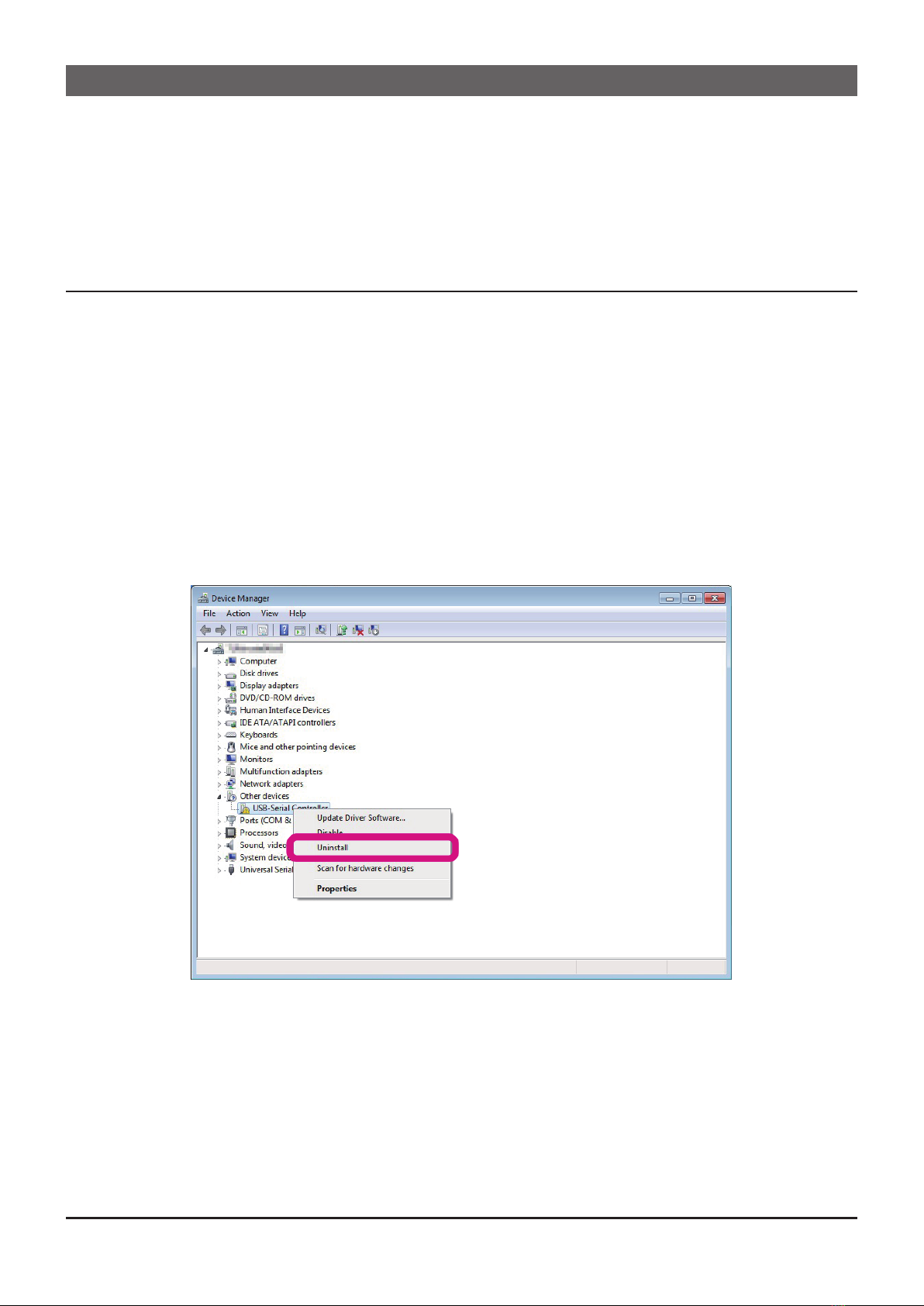
How to Uninstall the Programming Cable Driver.. 6
Installing the Memory Programmer ......................... 7
Preparation........................................................... 7
How to Uninstall the Memory Programmer ............. 8
Basic Operation........................................................ 9
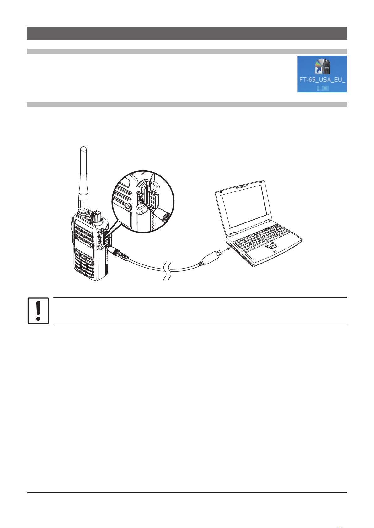
Activating the Memory Programmer........................ 9
Connecting the FT-65R/E or FT-25R/E to the com-
puter ........................................................................ 9
Set the Comm Port Number of the SCU-35 driver ....
.............................................................................. 10
Read the settings from the transceiver.................. 10
Edit the transceiver settings with the Memory Pro-
grammer .................................................................11
Write the settings to the transceiver .......................11
About Memory Programmer.................................. 12
Initial screen .......................................................... 12
Menu Bar ................................................................. 13
File menu............................................................... 13
New ............................................................... 13
Open.............................................................. 13
Save .............................................................. 13
Save as ......................................................... 13
Exit ................................................................ 13
Edit menu .............................................................. 14
CH. Edit......................................................... 14
Function Setup .............................................. 14
Bank Channel................................................ 14
Set menu ............................................................... 15
Set COM........................................................ 15
Set Initialization ............................................. 15
Program menu....................................................... 15
Read From Radio.......................................... 15
Write To Radio............................................... 15
View menu............................................................. 16
Tool Bar ......................................................... 16
Status Bar...................................................... 16
Version menu ........................................................ 16
About FT_65(25)_XXX .................................. 16
Switching buttons .................................................. 17
Normal........................................................... 17
PMS............................................................... 17
VFO-A............................................................ 17
VFO-B ........................................................... 17
Home............................................................. 17
P.................................................................... 17
Set Value Input screen ........................................... 18
RX Frequency ............................................... 18
Offset Frequency........................................... 18
Auto Offset..................................................... 18
Offset Direction.............................................. 18
CTCSS Decode............................................. 18
CTCSS Encode............................................. 18
DCS Decode ................................................. 18
DCS Encode.................................................. 18
Channel Name .............................................. 18
TX Power....................................................... 18
Scan .............................................................. 19
Wide Narrow.................................................. 19
Step............................................................... 19
SQL Type....................................................... 19
Bank .............................................................. 19
Troubleshooting ..................................................... 20
FT-65/25 cannot receive or transmit data to the
computer. The Data transfer does not start........ 20
The data transmission has stopped before com-
pletion................................................................. 20
Table of Contents

Introduction
The Memory Programmer software uses a Personal Computer to quickly enter and save
the FT-65R/E and FT-25R/E memory channel frequencies and data. Also, the many Set
Mode (Menu) settings may be adapted for individual operating preferences. All of the
information is saved. The setting data can be imported from an FT-65R/E or FT-25R/E,
and the edited setting data can be transferred to a FT-65R/E or FT-25R/E .
Edit the RX frequencies, memory names, CTCSS/DCS settings, transmit power, etc.
that is related to the memory channels.
Edit the Memory bank link setting.
Congure the various Set (Menu) Mode options on the computer monitor screen.
Use handy editing functions, such as copy and paste for each line of memory channel
number.
About this manual
This manual contains symbols and conventions to call attention to important informa-
tion.
Symbols Description
This icon indicates cautions and alerts the user should be aware of.
This icon indicates helpful notes, tips and information.
This icon indicates other pages containing relevant information.
The procedures on this manual is explained for a Windows 7®(64 bit) computer for
the purpose of illustration.
Important Notes
Before downloading this software, please read the “Important Notes” carefully.
•Copyrights and all other intellectual property rights for the software, as well as the
software manual, are the property of YAESU MUSEN CO., LTD.
•The revision, modication, reverse engineering, and decompiling of this software
is prohibited. Redistribution, transfer, and resale of downloaded files are also
prohibited.
•Do not resell the software or manuals.
•All responsibility for the use of this software lies with the customer. Yaesu cannot
be held responsible in any way for any damages or losses, which may be
incurred by the customer as a result of using this software.
Read this manual thoroughly and install the software.
System Requirements
Supported Operating Systems
Microsoft® Windows® 10 (32 bit/64 bit)
Microsoft® Windows® 8.1 (32 bit/64 bit)
Microsoft® Windows® 7 (32 bit/64 bit)
CPU
The performance of the CPU must be able to satisfy the operating system requirements.
2
FT-65R/E FT-25R/E Memory Programmer

RAM (system memory)
The capacity of the RAM (system memory) must be more than sufcient to satisfy the
operating system requirements.
HDD (Hard Disk)
The capacity of the HDD must be more than sufcient to satisfy the operating system re-
quirements.
In addition to the memory space required to run the operating system, about 50 MB or
more of additional memory space is required to run the program.
Necessary PC peripheral interfaces
USB port (USB 1.1 / USB 2.0)
Required Cable
Programming Cable SCU-35
Before using the SCU-35 Programming Cable, install the designated driver on
the computer.
Trademarks
Microsoft®, Windows®, Windows® 7, Windows® 8.1. and Windows® 10, are registered
trademarks in the United States and other countries.
The ow sequence of the Memory Programmer
The procedure when using Memory Programmer for the rst time is as follows:
Installing the SCU-35 driver software (Page 4)
↓
Installing the Memory Programmer (Page 7)
↓
Basic Operation (Page 9)
↓
About Memory Programmer (Page 12)
3
FT-65R/E FT-25R/E Memory Programmer

Set up the Memory Programmer
Installing the SCU-35 driver software
Preparation
Download the SCU-35 driver software from the Yaesu Website (http://www.yaesu.com/).
Extract the downloaded (PL2303_Prolic_DriverInstaller_v****.zip) le.
Start up the computer as an “Administrator” user.
Before installing the driver, make sure that the SCU-35 Programming Cable is
disconnected from the computer.
SCU-35 Driver Software Installation
1. Double-click the “PL2303_Prolic_DriverInstaller_v****.exe” le, in the same
unzip folder.
When the [User Account Control] dialog box opens, click the [Yes].
2. The dialog box, which is shown at the right,
will open. Click the [Next], to initiate the in-
stallation of the driver.
3. When the installation is finished, the dialog
box shown right will open. Click the [Finish],
to complete the installation of the driver.
4. Connect the SCU-35 Programming Cable to the USB jack on the computer.
• The SCU-35 Programming Cable will be recognized automatically.
• Conrm that the SCU-35 driver is installed correctly, If the driver fails, proceed
to “When the Driver Software Installation Fails” on the next page.
5. Click the [Start] button in the tool bar, then right-click the [Computer] button.
6. Click the [Properties], then click the [Device Manager] button.
7. When the [User Account Control] dialog box opens, click the [Yes] button.
4
FT-65R/E FT-25R/E Memory Programmer

Set up the Memory Programmer
8. Open the [Device Manager] dialog box, then double-click the [Ports
(COM&LPT)] button.
• When the “Prolific USB-to-Serial Comm Port (COM X)” (X: Comm Port
Number) is displayed, the SCU-35 Programming Cable is functioning
normally.
• To connect the transceiver to the PC, keep the Comm Port Number in mind.
When the Driver Software Installation Fails
The driver installation may fail when:
The installation wizard is canceled during the installation.
The SCU-35 Programming Cable is connected to the computer before installing
the driver.
When the installation of the driver fails:
1. Open the [Device Manager] dialog box, as described in step 6 of the “SCU-35
Driver Software Installation” instruction section
2. Right-Click [Other devices], which is appended to the “!” icon, then click [Un-
install], to uninstall the driver.
3. Retry the installation of the driver.
5
FT-65R/E FT-25R/E Memory Programmer

Set up the Memory Programmer
How to Uninstall the Programming Cable Driver
If you wish to uninstall the SCU-35 Programming Cable driver, perform the following pro-
cedures:
1. Disconnect the SCU-35 Programming Cable from the computer.
2. Click [Start] à[Control Panel] à[Uninstall a program].
3. Click “PL- 2303 USB-to-Serial”, then click
[Uninstall].
4. Click [Next].
5. Click [Yes] to uninstall the SCU-35 program-
ming cable driver.
6. When uninstall is finished, the dialog box
shown to the right will open. Click [Finish] to
complete removal of the SCU-35 program-
ming cable driver.
6
FT-65R/E FT-25R/E Memory Programmer

Set up the Memory Programmer
Installing the Memory Programmer
Preparation
Download the Memory Programmer from the Yaesu Website (http://www.yaesu.com/).
Currently there are two different destination versions of the FT-65R/E or FT-25R/E
transceivers: USA_EU (DST: USA/EU), and EXP (DST: EXP/CHN).
Download the zip file “FT-65(25)_USA_EU_Setup” for USA/EU, or the zip file “FT-
65(25)_EXP_Setup” for EXP” destination versions from the YAESU website files
section.
Extract the downloaded zip le.
Start up the computer as an “Administrator” user.
For example: the procedure to install the FT-65 memory programmer (USA/EU version)
on a Windows7® (64 bit) computer is shown below.
1. Double-click the “FT-65_USA_EU_Setup.exe” le in the same unzip folder.
When the [User Account Control] dialog box opens, click [Yes].
2. The dialog box shown to the right will open.
Click [Next], to initiate the installation of the
Memory Programmer.
3. When uninstall is finished, the dialog box
shown to the right will open. Click [Finish] to
complete the Memory Programmer proce-
dure.
7
FT-65R/E FT-25R/E Memory Programmer

Set up the Memory Programmer
How to Uninstall the Memory Programmer
For example: the procedure to uninstall the FT-65 Memory Programmer (USA/EU ver-
sion) on a Windows 7® (64 bit) computer is shown below.
1. Disconnect the SCU-35 Programming Cable from the computer.
2. Click [Start] à [Control Panel] à [Uninstall a program].
When [Uninstall a program] is not displayed, click [Programs and Features].
3. Click on [FT-65_USA_EU *.**] and then click
[Uninstall].
When the [User Account Control] dialog box
opens, click [Yes].
8
FT-65R/E FT-25R/E Memory Programmer

Basic Operation
Activating the Memory Programmer
Double-click the desktop icon (shown at the right), to activate the Memory
Programmer.
To exit the Memory Programmer, click on [Exit] in the [File] menu.
Connecting the FT-65R/E or FT-25R/E to the computer
1. Turn the transceiver OFF.
2. Connect the SCU-35 Programming Cable to the USB port on the computer
and connect the plug to the transceiver MIC jack.
SCU-35 Programming Cable
To MIC jack To USB port
Do not disconnect the SCU-35 Programming Cable while transferring the data.
3. Turn the transceiver ON.
9
FT-65R/E FT-25R/E Memory Programmer

Basic Operation
Set the Comm Port Number of the SCU-35 driver
1. Click the [Set COM] parameter in the [Set]
menu.
The “Communication Setting” window will
open.
The [Set COM] parameter may also be
set by clicking the logo.
2. Select the Comm Port Number, then click
[OK].
The Comm Port Number of the SCU-35
driver will be shown in step 8 of the “SCU-35
Driver Software Installation” procedure.
Read the settings from the transceiver
To write the settings to the transceiver, see “Write the settings to the
transceiver” on page 11.
1. Click the [Read From Radio] parameter in the
[Program] menu.
The [Read From Radio] parameter may
also be set by clicking the logo.
2. The confirmation popup window will open,
then click [OK].
The completion percentage popup window
will appear.
3. If reading is successful, the popup window
will open, then click [OK].
10
FT-65R/E FT-25R/E Memory Programmer

Basic Operation
Edit the transceiver settings with the Memory Programmer
1. Double-click the cells of each channel to en-
ter the data.
2. Input the alphanumeric characters, or select
the settings from the dropdown list of each
channel.
The data may be copied and pasted to the
desired channels.
The rows of each channel may be Cut, Copied or Pasted (Ctrl+X, Ctrl+c or
Ctrl+V), However some of the cells on each channel row may not be Cut, Copied
or Pasted (Ctrl+X, Ctrl+C or Ctrl+V).
For more details on the contents of each setting, see page 12.
Write the settings to the transceiver
Memory programmer data may only be written to the same model transceiver.
1. Click the [Write To Radio] parameter in the
[Program] menu.
The [Write To Radio] parameter may also
be set by clicking the logo.
2. The Confirmation popup window will open,
then click [OK].
The Completion percentage popup window
will appear.
3. If the writing is successful, a popup window
will open, then click [OK].
11
FT-65R/E FT-25R/E Memory Programmer

About Memory Programmer
Initial screen
This is the initial screen displayed when starting the memory programmer.
Name Description
Menu Bar Click the menu bar to read from the radio, write to ra-
dio, set language, set initialization, etc. 13
Tool Bar
Click the [Tool bar] parameter in the [View] menu to
display or hide the Tool bar. The Tool bar includes
buttons for some of the most common commands in
the Memory Programmer.
16
Switching Button Click each button (PMS, VFO-A, etc) to switch the
display settings. 17
Status Bar
Click the [Status Bar] parameter in the [View] menu
to display or hide the Status Bar. The Status Bar dis-
plays the date and the time.
16
Set Value Input
Screen
Double-click each channel setting to input the setting
values. 18
12
FT-65R/E FT-25R/E Memory Programmer

Menu Bar
File menu
New
Open a new conguration le from the disk drive.
Click the [New] parameter in the [File] menu to open the Memory Programmer default
conguration le.
The default settings are set in the default conguration le.
This [New] menu screen operates the same, either by using the dropdown lists, or by
clicking on the icons, as shown in the gures above.
Open
Open a previously-saved conguration le from the disk.
Click the [Open] parameter in the [File] menu, a pop-up window appears which shows all
the saved les in the specied path.
This [Open] button operates the same as the right icon in the gures above.
Save
Save the programming session to the disk with the same name and directory.
Click the [Save] parameter in the [File] menu, a caution message will appear. If you
agree to over-write the current le, click [OK].
This [Save] button operates the same as the right icon in the gure above.
Save as
Save the programming session to the disk with a new name.
Click the [Save As] parameter in the [File] menu, a pop-up window will appear which dis-
plays all the current les saved to the specied path.
To save the programming session with a new name, type the new le name in the bot-
tom box, then click [OK].
Exit
Exit the program and close the window.
13
FT-65R/E FT-25R/E Memory Programmer

Menu Bar
Edit menu
CH. Edit
Click [CH Edit], to display the set value input selection list. This list operates the same as the
switching buttons. For details, see “Switching buttons” on page 17.
Function Setup
Use this function to customize the various functions of the FT-65/25 according to your
preferences.
Click the [Function Setup] parameter in the [Edit] menu to open the “Function Setup”
window.
Bank Channel
A combination of up to 100 memory channels, and preset memory channels can be reg-
istered to each BANK (BANK 1 to BANK 10). When selecting a bank, only channels reg-
istered to the bank will be recalled.
14
FT-65R/E FT-25R/E Memory Programmer

Menu Bar
Set menu
Set COM
Set the Comm Port number of the SCU-35 driver.
This [Set COM] selection operates the same as clicking the icon in the figure at the
above right.
Set Initialization
Initialize the conguration content of the Memory Programmer.
If the present conguration has not been saved to the disk, you will be prompted to con-
rm whether or not you wish to save the new data.
Program menu
Read From Radio
This command transfers the settings data of the FT-65/25 to the memory programmer.
This [Read From Radio] operates the same as the right icon in the gure above.
Read data may be stored to the computer les, using the [Save] or [Save as]
commands in the [File] menu.
For details, see “Read the settings from the transceiver”.
Write To Radio
This command downloads the Memory Programmer data from the computer to the FT-65/25.
This [Write To Radio] selection operates the same as the right icon in the gure above.
For details, see “Write the settings to the transceiver”.
15
FT-65R/E FT-25R/E Memory Programmer

Menu Bar
View menu
Tool Bar
Click the [Toolbar] parameter in the [View] menu to display or hide the Tool bar. The tool
bar includes buttons for some of the most often used commands in the Memory pro-
grammer. A check mark appears next to the [Toolbar] parameter when the Tool bar is dis-
played.
Status Bar
Click the [Status Bar] parameter in the [View] menu to display or hide the Status Bar.
The [Status Bar] displays the date and the time. A check mark appears next to the [Status
Bar] parameter when the Status Bar is displayed.
Version menu
About FT_65(25)_XXX
Click the [About FT-65(25)_XXX(destination version)] parameter in the [Version] menu,
to display the version and copyright of the Memory Programmer. This menu operates the
same as the icon in the gure at the right above.
16
FT-65R/E FT-25R/E Memory Programmer

Switching buttons
Normal
Click the [Normal] button to change the normal operation settings.
PMS
Click the [PMS] button to change the PMS memory channel settings.
VFO-A
Click the [VFO-A] button to change the default settings of VFO-A.
VFO-B
Click the [VFO-B] button to change the default settings of VFO-B.
Home
Click the [Home] button to change the default settings of the Home channel.
P
Click the [P] button to change the default settings of the [P1]-[P4] keys of the transceiver.
17
FT-65R/E FT-25R/E Memory Programmer

Set Value Input screen
RX Frequency
Enter the RX.
Enter the desired receive frequency.
Offset Frequency
This item sets the offset frequency for the repeater.
Auto Offset
This item sets the auto offset frequency ON or OFF for the repeater.
Offset Direction
This item selects the offset direction for the repeater.
• Plus
The transmit frequency is shifted to the plus offset.
• Minus
The transmit frequency is shifted to the minus offset.
• Simplex
The transmit frequency is not shifted.
CTCSS Decode
To set the receive CTCSS tone frequency.
CTCSS Encode
To set the transmit CTCSS tone frequency.
DCS Decode
To set the receive DCS code.
DCS Encode
To set the transmit DCS code.
Channel Name
Enter the desired memory name (up to 8 digits).
TX Power
This item selects the TX Power.
18
FT-65R/E FT-25R/E Memory Programmer

Setting the Items
Scan
Select the scanning condition for receiving channels.
• Scan
Performs scanning according to the set mode basic setting - SCAN RESUME.
• Skip
Skips the designated memory channels during scanning.
Wide Narrow
This item selects wide/narrow bandwidth on the FM mode.
• Wide
Use for FM broadcasting.
• Narrow
Use for narrow bandwidth ham radio and advisory radio.
Step
Sets the channel step for receiving channels. Normally, when a frequency is entered, the
optimal channel step will be automatically set according to the frequency.
SQL Type
This item selects the Tone Encoder and/or Decoder mode.
Bank
A combination of up to 200 memory channels and PMS channels can be registered to
each BANK, of BANK 1 to BANK 10. In the column of each channel, check the box of the
BANK to register the desired channel.
When selecting a bank, only channels registered to the bank will be recalled.
19
FT-65R/E FT-25R/E Memory Programmer
Other manuals for FT-65R
5
This manual suits for next models
3
Table of contents
Other Yaesu Two-way Radio manuals

Yaesu
Yaesu VX-400 User manual

Yaesu
Yaesu ADMS-13 User manual

Yaesu
Yaesu FT-212RH User manual

Yaesu
Yaesu FT-991 User manual

Yaesu
Yaesu FT-1807M Manual

Yaesu
Yaesu VX-7R Assembly instructions

Yaesu
Yaesu FT1DR Installation guide

Yaesu
Yaesu FT-60E User manual

Yaesu
Yaesu VXA-100 User manual

Yaesu
Yaesu ADMS-15 User manual

Yaesu
Yaesu VX-5R Quick start guide

Yaesu
Yaesu VX-451 User manual

Yaesu
Yaesu FT-60E Operation and maintenance manual

Yaesu
Yaesu FT-51R Manual

Yaesu
Yaesu FT-8800R User manual

Yaesu
Yaesu VX-1R User manual

Yaesu
Yaesu FT-60R User manual

Yaesu
Yaesu VX-2R Manual

Yaesu
Yaesu FT-450 Manual

Yaesu
Yaesu FT-60R User manual