-5-
NOTE: If ground wire to the source is not available, you will
needtofindyourowngrounding point.Locateametal
areaclosetothePEQ-200 thatprovidesagoodground
point(preferablythefloor). Eliminateunwantedpaint
andother contaminantsusingawirebrushorsandpa-
per.Terminatetheblackwireusingthecorrectsizeof
ring terminal and attach it to the bare metal. Spread
Siliconeoverthescrewandbaremetaltopreventrust
andcorrosion.
3.
RemoteTurn-OnConnection
(
Orangewire
)
ThePEQ-200 isturnedonbyapplying+12volts to the
remote turn-on terminal (REM) of the cable 4-Pin
connector harness. The wire lead to this terminal
should be connected either to the "Auto-Antenna"
leadfromthecarstereo,ortosomeotherpointwhich
will provide a +12 V dc supply only when the car
stereoisturnedon. Ifthecarstereodoesnotprovide
anAuto-Antennalead,theremoteturn-onleadmaybe
wiredtoan"Accessory"or"Radio"terminalinthecar's
fuseblock. ThiswillturnthePEQ-200onandoffwith
theignition key,regardlessofwhetherthecarstereo
is on or off. The remote turn-on lead of the cable
harnessdoesnothavetocarrylargecurrents,so#20
gaugewiremaybeusedforthisapplication.Afterthe
remote connection has been made, insert the cable
connectorintothe4-pinjackattherearoftheunitwhile
pressing the key tab; it will snap into place.
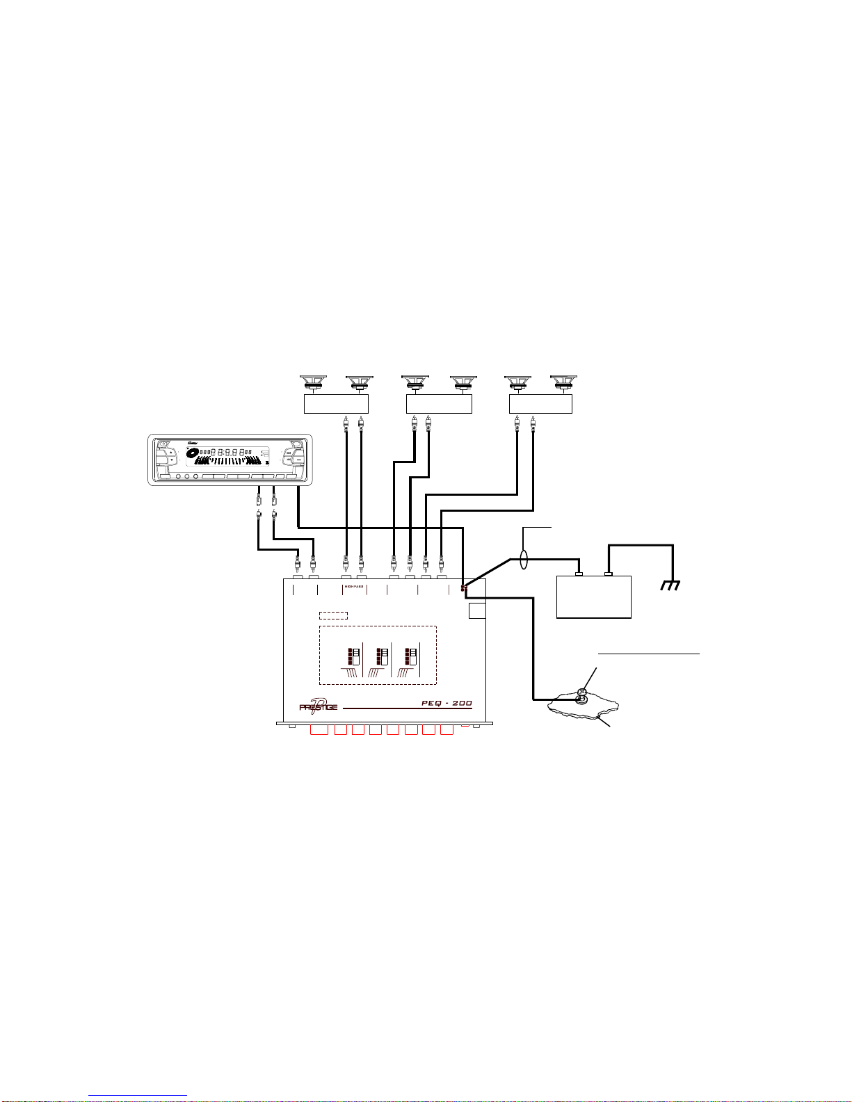
WIRINGINSTRUCTIONS
The wiring of your crossover equalizer will depend on the
systemand speakers youareusingbut willeitherbea 2-way
(bassandmidrange/high) or 3-way(bass,midrangeandhigh)
applicationusing 2or4channelsof inputfromthecar stereo.
The following pages illustrate the input and output wiring for
these types. Please refer to the appropriate diagram for the
systemconfiguration youareusing.
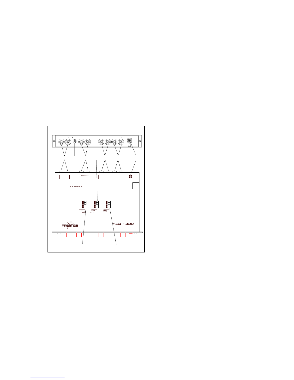
Thepowerconnectionsforthisunitareaccomplishedusingthe
suppliedmodular4-pinconnectorwiringharness(item18). The
wiringharnesscontainsthreecolor-codedwires.
Connecting these wires should not be overly difficult if the
following guidlines are adhered to: (See the installation dia-
gram.)
1.
PowerConnection
(
Redwire
)
Pullthesourceunit(radio,amplifier,etc.)outfromthe
dashfarenoughuntilthewiresareexposedattherear
of the unit. Using a digital voltmeter, find a constant
+12Vdc lead for the radio, and splice into this wire.
Splice or solder the red wire from the wiring harness
and connect it inline with the +12Vdc wire using a
barrelconnectorofappropriatesize.
2.
GroundConnection
(
Blackwire
)
Locatethegroundwiresuppliedtothesourceunit and
splice into it. Take the black wire from the wiring
harnessandconnectit in linewiththegroundwireby
splicingandorsoldering.