audiowireless AWT-1 User manual

User Manual
v1.1

AWT-1 User Manual V1.1 i
User Manual
Contents:
Foreword..........................................................................................................1
Safety Instructions ...........................................................................................1
Product Contents.............................................................................................1
General Description.........................................................................................2
Product Overview.............................................................................................3
Audio Input Socket.......................................................................................3
LED Indicators Modulation Level and Battery Status ..................................3
Antenna Socket .........................................................................................3
Push Button Controls ...................................................................................4
Frequency Label...........................................................................................4
Battery Compartment ...................................................................................5
Belt Clip........................................................................................................5
LCD Display .................................................................................................6
Using the AWT-1..............................................................................................7
Tuning the transmitter ..................................................................................8
Tuning By Frequency................................................................................8
Saving Custom Frequency .......................................................................8
Tuning By UHF TV Channel and Sub-Channel.........................................9
Unit Name ..................................................................................................10
Mic. Gain....................................................................................................10
Low-Cut Filter.............................................................................................10
RF Transmission Power.............................................................................10
Locking and Unlocking the Unit..................................................................10
Power Settings (On-Mode).........................................................................11
Resetting preferences................................................................................12
Display settings..........................................................................................12
Unit Information..........................................................................................12
Further Technical Information........................................................................13
Antenna Data for Flexible Wire Antennae ..................................................13
Model Variants and Switching Bands:........................................................14
Mic Input Connection Details......................................................................15
Cable end connectors ................................................................................15
Standard Transmitter Input Cables Details.................................................17
Cable Ended Microphones.........................................................................22
Specifications:................................................................................................23
RF Transmission System ...........................................................................23
AF Characteristics......................................................................................23
Modulation Indicators.................................................................................23
Battery Status Indicators ............................................................................23
Accessories................................................................................................24
AWT-1

AWT-1 User Manual V1.1 1
Foreword
Thank you for choosing Audio Wireless
We aim to offer the best quality products alongside a quick and reliable service
for all our customers. Please take some time to read our instruction manual to
ensure you get the most out of our equipment.
Safety Instructions
Please read these instructions carefully before using the unit to avoid
injury and damage to your AWT-1 unit.
Always include these instructions when passing the unit on to third parties
Never open the electrical units; if the units are opened then the warranty
becomes null and void.
Protect the unit from damp and wet conditions, as water entering inside
can cause damage to the unit.
Use only a slightly damp cloth to clean the unit. Do not use any cleansing
agents or solvents.
Product Contents
1 AWT-1 Transmitter
1 Belt Clip
1 Antenna
1 Quick Start Guide
1 Carrying Case

AWT-1 User Manual V1.1 2
General Description
The AWT-1 transmitter offers the greatest flexibility and sound quality for crews,
operators and sound recordists, whether working internationally or simply under
challenging RF conditions.
Its sophisticated structure comes in a lightweight yet rugged, CNC machined
aluminium case, designed for extra strength and durability as well as the ability to
withstand the heavy demands of on-location use.
The unit requires a single AA battery which fits into its unique battery
compartment designed for fast and easy battery replacement by an easy-twist
compartment cover, with a reassuring click-stop mechanism.
Product Features:
Switching bandwidth up to 120MHz
Tunable in 25kHz steps
Switchable RF output power
Top-level flexibility for international working
Compact design, with rugged all-metal construction
1 x AA alkaline provides up to 5 hours operating time or
using a lithium battery even longer
Easy-twist battery compartment cover, with click-stop reassurance
External powering capable with adaptor leads
Unique mic-pre design maximizes audio quality
Input sensitivity from -50dBu to 0dBu before limiting
Adjustable low-cut filter
Easy operation by backlit LCD with programmable functions
Battery-level indication and transmitted “low batt” warning system
Pilot-tone carrier
Reliable, professional-grade connectors
Please Note:
To ensure best performance it is recommended to only use the AWT-1
transmitter series with the matching AWDR-1 diversity receiver series.

AWT-1 User Manual V1.1 3
Product Overview
Audio Input Socket
The specific socket type may vary by unit. The following connectors are available:
Small 6-Pin LEMO™connector (pictured above)
Large 6-Pin LEMO™connector
Mini 5-pin BM5 Connector (for TA5F cable)
The 6-Pin LEMO™connectors allow for the microphone-input cable to be
connected by a push-pull action. The Mini 5-pin BM5 Connector allows for the
microphone-input cable to be connected by a push-latch into TA5F. For more
information on pin details please see the Connection details in the Further
Technical information section of this manual.
LED Indicators
Modulation Level and Battery Status
The three LEDs show the modulation level of the transmitted signal and the
battery status. When the battery level is sufficient the light is green and when the
battery is low the LED turns red, as an indicator to change the battery as soon as
convenient. The modulation level LEDs (-10 and 0dB) indicate the audio level, for
straightforward adjustment of the transmitter gain and this enables repeatable
levels to be set with ease.
Antenna Socket
The detachable antenna can be connected into this miniature 50SMA coaxial
socket by a simple screw-on action.
TOP VIEW
Antenna
Socket
Audio Input Socket
(Model Specific)
Battery/
Modulation
LED Indicators

AWT-1 User Manual V1.1 4
Push Button Controls
All user adjustments to the AWT-1 are made via three push buttons. Primarily use
the UP and DOWN to scroll through menu’s and the SET-PWR to select choices.
Alternatively at any time the SET-PWR button can be held down to turn the
transmitter off (and back on) and by holding both the UP and DOWN buttons can
you toggle the LOCK function.
Frequency Label
Indicates the tuning bandwidth of the transmitter, where it is possible to tune to
any frequency within this range in steps of 25 kHz. Alternatively the user may
tune to standard UHF TV channels with pre-coordinated sub channels.
FRONT VIEW
Antenna Socket
Audio Input Socket
Frequnecy Label
(Model Specific)
Multi-function
LCD Display
Push Button Controls
Battery Compartment

AWT-1 User Manual V1.1 5
Battery Compartment
The AWT-1's single AA battery is held in place by a captive, easy-twist
compartment cover, with a click-stop mechanism for quick, reliable changes
possible by feel alone.
Simply slide open the rotating battery cover to insert a single AA battery into the
compartment. And with another slide rotate it back for a reassuring click as the
compartment is closed.
Belt Clip
The Belt clip provided with the AWT-1 can be used to mount the unit to clothing
and belts, etc. Being detachable it also allows for the unit to be mounted upside
down if required.
Please Note:
When inserting the battery please remember to follow the polarity guidance
indicated on the rear face of the unit. Remove the battery when the unit will not
be used for extended periods of time.
To Open Rotate clockwise
To Close Rotate anti-clockwise
AWT-1 User Manual V1.1 6
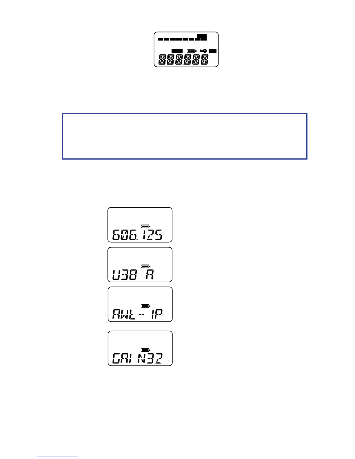
LCD Display
The backlit multifunction LCD display provides clear access to all the available
control menus and functions of the AWT-1. Permanently displayed, irrespective of
the currently selected menu, is the continuous AF metering of the signal level and
the battery level icons.
By default the following main menus are available:
Menu
Name
Example Display
Menu Description & Function
Frequency
Displays Transmission Frequency and
allows for adjustment when selected
Channel
Displays Transmission Channel & Sub-
Channel as well as allowing for adjustment
when selected
Name
Displays Unit Name and allows for
adjustment when selected
Gain
Displays Microphone Gain and allows for
adjustment when selected
-50 -40 -30 -20 -10 0
AF
MHZ
-50 -40 -30 -20 -10 0
AF
CH
-50 -40 -30 -20 -10 0
AF
-50 -40 -30 -20 -10 0
AF
Please Note:
The display backlight and LED indicators (when active) illuminate for
approximately 15 seconds from last button press and subsequently turn off to
optimize battery use.
-50 -40 -30 -20 -10 0
LIMIT
AF
HPF
CH
MHZ
MUTE

AWT-1 User Manual V1.1 7
Menu
Name
Example Display
Menu Description & Function
Low-Cut
Allows for adjustment of the Low Cut Filter
when selected. Note the “HPF” symbol
appears when this has been activated.
RF
Displays RF Power and allows for adjustment
when selected
Lock
Displays current Lock state and allows
adjustment of the Lock Setting
On-Mode
Allows for adjustment of the Power-On mode
Reset
Option to return all settings to factory defaults
Display
Options for displaying or hiding certain Menus
Info.
Gives Unit Info
-50 -40 -30 -20 -10 0
AF
H P F
-50 -40 -30 -20 -10 0
AF
-50 -40 -30 -20 -10 0
AF
-50 -40 -30 -20 -10 0
AF
-50 -40 -30 -20 -10 0
AF
-50 -40 -30 -20 -10 0
AF
-50 -40 -30 -20 -10 0
AF
Please Note:
All menus are set to be shown by default. However within the display menu it is
also possible to choose to show only one out of the Frequency, Channel or
Name menus and hence hide the other two.

AWT-1 User Manual V1.1 8
Using the AWT-1
Tuning the transmitter
There are two methods available for tuning the transmitter allowing both complete
flexibility and convenience. These are tuning by Frequency or by numbered UHF
TV Channel with pre-coordinated Sub-Channels.
Tuning By Frequency
By default the Frequency menu is the first menu that appears upon turning ON
the unit. On the Frequency menu the currently used frequency for transmission is
displayed on the screen in MHz.
1. To tune, press the SET-PWR button to start the frequency select mode.
In this mode the displayed frequency flashes.
2. Use the UP or DOWN buttons to scroll through the entire switching
bandwidth in steps of 25 kHz.
3. To save the selected frequency press the SET-PWR button to store,
the confirmatory “SAVED”message will appear.
Saving Custom Frequency
The transmitter can save up to 24 frequencies to the user customisable channel
bank listed as “VAR XX” in the channel menu. To store a frequency - simply
repeat the above but after selecting the frequency quickly press the SET-PWR
button again whilst the “SAVED” message appears.
Then select the desired custom channel, named “VAR 01” to “VAR 24” and
hit the SET-PWR button to select and display the confirmatory “SAVED”
message.
Please Note:
There are 24 user customisable channels available, which after being set in the
frequency mode menu, are then accessible via the channel mode menu,
explained further below.
Remember to change display mode to “All” to have both menus available.
Resetting the unit will clear all user channel pre-sets.

AWT-1 User Manual V1.1 9
Tuning By UHF TV Channel and Sub-Channel
Within the Channel Menu the previously selected UHF TV Channel and
sub-channel are displayed. From this menu you can tune the transmitter to the
pre-set channels within the switching bandwidth.
A UHF TV channel (8MHz wide) has up to 12 pre-coordinated sub-channels
(labelled A through to M, excluding the letter I). These have been calculated to
avoid interference between them, maximizing the use of the available spectrum.
1. To tune to a UHF TV channel, press the SET-PWR button whilst on the
Channel Menu to start the channel select mode. In this mode the displayed
channel information flashes.
2. Use the UP or DOWN buttons to scroll through all the available channels
and press the SET-PWR button to select one. As well as the model
dependent range of UHF TV channels are the user customisable “VAR-
XX” channels available.
3. Use the UP or DOWN buttons to scroll through the available sub-channels
and press the SET-PWR button to select your choice and “SAVED”
message appears to confirm your selection. Please note, each UHF TV
channel may have up to 12 pre-coordinated sub-channels, e.g. “A>M”.
Please Note:
Channel 38 (606-614 MHz), commonly used in the UK is presented with 2 sets
of sub-channels. The Audio Wireless co-ordinated “A>M” set and the
alternative JMFG “38-XX” option that grants a set of sub-channels numbered
from 1-10. Do not use sub-channels from both sets simultaneously.
For users in the UK it should be noted that channel 38, is the only general
purpose channel recommended for use by the JMFG in public spaces.

AWT-1 User Manual V1.1 10
Unit Name
For convenience and quick distinction between units it is possible to name the
transmitter with a six-character alpha-numerical name. The characters available
A-Z, 0-9 and 3 special characters; “*”, “-”and “ ”.
By default the name given is the Units Model Number, e.g. “AWT-1P”.
Mic. Gain
In the Gain Menu, it is possible to adjust the mic-amplifier gain with the UP and
DOWN buttons anywhere between 0 and -51dB. Adjust the gain such that during
normal volume of speech the ‘-10’ dB LED lights regularly. For common lavaliere
microphones like Sanken™ COS-11D the advised starting level is -30dB.
Low-Cut Filter
To reduce unwanted low-frequency noise such as wind and handling noise, you
can activate a low-cut filter.
There are 3 pre-sets available:
FLAT No Effect
CUT 1: - 6dB @ 88Hz
CUT 2: - 6dB @ 120Hz
RF Transmission Power
In the ‘RF’ menu the transmission power can be adjusted between High (50mW),
Medium (30mW) and Low (10mW).
Please Note:
It is the responsibility of the User to follow their residing territory’s broadcasting
regulatory body limits for RF power output.
Please Note:
When “CUT 1” or “CUT 2” is selected, the “HPF” icon will appear on the
screen.

AWT-1 User Manual V1.1 11
Locking and Unlocking the Unit
The AWT-1 is designed with a LOCK function to help prevent any undesired
changes to settings. As well as a basic toggle lock mode is a more robust Super-
Lock (“SULOCK”) which can only be removed by removing the battery or the
external powering source cabling.
The general Lock can be activated and de-activated at any time by pressing and
holding both the UP and DOWN keys until the key icon appears or disappears on
the LCD display. It can also be set via the Lock menu and selecting “LOCK” but it
can only be unlocked by holding both the UP and DOWN keys.
The “SULOCK” mode is activated within the Lock menu in the same way but can
only be UNLOCKED by removing the power from the unit.
It should be noted both Lock modes restrict any changes to any of the menu
options available but only in “LOCK” mode can the unit can still be powered off by
a long press of the SET-PWR button. When either lock mode is activated the key
icon will appear and “LOCK” or “SULOCK” will be displayed when any setting
changes are attempted.
Power Settings (On-Mode)
The AWT-1 features two POWER-ON modes; Manual and Automatic. The
Manual mode allows the unit to be turned ON/OFF by holding the SET-PWR
button. In the Automatic mode the transmitter will power on as soon as a battery
is inserted and may be powered down by holding the SET-PWR button.
Battery performance can be optimized by using the lower RF power outputs, but
note this may affect transmission range. An on-site test is recommended before
use to establish the appropriate settings for each usage scenario.
The lower RF power setting is also recommended when a large number of
systems are employed in small vicinity.

AWT-1 User Manual V1.1 12
Resetting preferences
Use this menu to reset the unit to the following Factory default settings:
Clear all User defined channels, VAR-01 to VAR-24
Unit Name –Unit Model name, e.g. “AWT-1P”
Gain –32dB
Low Cut Filter –Flat
RF Power –Medium
Lock Mode –Unlocked
On Mode –Manual
Display –All
To Reset the AWT-1, press the SET-PWR button whilst the Reset Menu is
displayed, and press the UP or DOWN button to select “OK” to reset or “NO” to
cancel. To confirm your choice press the SET-PWR button. After resetting the
“SAVED” message will be displayed.
Display settings
In certain usage situations it may be preferred to hide some of the menus. For
example, if the transmitter is to only be tuned using frequencies it may be
preferable to hide the channel menu, or vice versa when tuning with UHF
channels and sub-channels. Alternatively, if the device has been tuned and will
not need to be change for an extended period of time it may be of benefit to
display only the Unit’s Name to quickly distinguish amongst other units.
The Menu Display options available are:
All –Display all Menus; Frequency, Channel and Name.
Freq –Display only the Frequency Menu & not the Channel or Name Menus.
Chan –Display only the Channel Menu & not the Frequency or Name Menus.
Name –Display only the Name Menu & not the Frequency or Channel Menus.
To change the displayed menus, simply hit the SET-PWR button whilst on the
Display Menu to start the Display menu select mode and cause the current
Display option to flash continuously. Then use the UP or DOWN buttons to cycle
to the desired setting and press the SET-PWR button to select your choice and
display the confirmation “SAVED” message.
Unit Information
Within the INFO menu it is possible to view the following unit information;
Serial Number - Unit Unique and same as on the rear casing
Model name - e.g. “AWT-1P”
Max switching frequency - In MHz, model specific
Min switching frequency - In MHz, model specific
Dc volt level - The voltage reading of the battery
Software version number - The Software version number

AWT-1 User Manual V1.1 13
Further Technical Information
Antenna Data for Flexible Wire Antennae
COLOUR CODE
CENTRE FREQUENCY
(MHz)
USABLE FREQUENCY
RANGE (MHz)
ACTIVE LENGTH (mm)
BLUE
560
510 - 620
125
BLACK
650
600 - 720
106
RED
750
700 - 800
88
NOTE: RX AND TX ANTENNA LENGTHS ARE SAME.
Active length is the length of the antennae from the connecting socket housing to the tip.

AWT-1 User Manual V1.1 14
500 MHz
600 MHz
700 MHz
BE1: 510-542
U1: 600-632
G2: 720-748
G4: 755-785
G3: 730-766
G5: 710-766 MHz
U5: 600-660 MHz
U6: 660-715MHz
FB1: 510-566 MHz
G6: 730-785 MHz
800 MHz
FB3: 710-785 MHz
FB2: 600-715 MHz
C1: 600-698 MHz
USA/CAN Exc. 608-614 MHz
Model Variants and Switching Bands: AWT-1 AWT-1dband AWT-1plus

AWT-1 User Manual V1.1 15
Mic Input Connection Details
The microphone input connection provides for:
Direct powering connection for electret microphones
A high sensitivity input for dynamic microphones (with TDC adaptor
cables)
Line input capability (with TLC adaptor cables)
External powering for transmitter (with TLCP adaptor cables)
There are 3 options of Mic audio input connectors:
1. Large 6-pin L6 LEMO connector –ERY.2C.306.CLL
Pin 1: Mic Input
Pin 2: Line Input
Pin 3: External Powering
Pin 4: Cable Detection
Pin 5: 0V Ground
Pin 6: M+ positive supply
2. Small 6-pin LEMO connector –ECG.0B.306.CLV
Pin 1: Mic Input
Pin 2: Line Input
Pin 3: External Powering
Pin 4: Cable Detection
Pin 5: 0V Ground
Pin 6: M+ positive supply
3. BM-5 connector –RT3NP
Pin 1: 0V Ground
Pin 2: M+ positive supply
Pin 3: Mic Input
Pin 4: External Powering
Pin 5: Line Input
3
1
4
6
2
5
5
1
4
2
6
3
5
1
2
4
3
Please Note:
Please note the above chassis mounted connectors are shown from the external
face view, whereas the following cable connectors shown are from the solder side.

AWT-1 User Manual V1.1 16
Cable end connectors
1. XLR connector –NC3FX
Pin 1: 0V Ground
Pin 2: AF + Φ
Pin 3: Linked to Pin 1
Pin 4: Linked to Pin 1
2. Large 6-pin L6 LEMO connector –FFA.2C.306.CLAL52
Pin 1: Mic Input
Pin 2: Line Input
Pin 3: External Powering
Pin 4: Cable Detection
Pin 5: 0V Ground
Pin 6: M+ positive supply
3. Small 6-pin LEMO connector –JGG.0B.306.CLAD52
Pin 1: Mic Input
Pin 2: Line Input
Pin 3: External Powering
Pin 4: Cable Detection
Pin 5: 0V Ground
Pin 6: M+ positive supply
4. TFA-5 connector –RT3FC
Pin 1: 0V Ground
Pin 2: M+ positive supply
Pin 3: Mic Input
Pin 4: External Powering
Pin 5: Line Input
5. Small 4-pin Hirose (dc) connector –HR10A-7P-4P
Pin 1: 0V Ground
Pin 2: Unused
Pin 3: Unused
Pin 4: External Powering
4
6
3
1
5
2
3
1
2
3
4
2
5
1
2
4
3
1
4
2
3
1
2
3
4

AWT-1 User Manual V1.1 17
Standard Transmitter Input Cables Details
TDC-6S: Dynamic microphone cable, terminated to small 6-pin LEMO to
XLR type female. (Colour code: Black sleeved)
TDC-6L: Dynamic microphone cable, terminated to large 6-pin LEMO to
XLR type female. (Colour code: Black sleeved)
Diagram same as above
TDC-6P: Dynamic microphone cable, terminated to TFA-5 to XLR type
female. (Colour code: Black sleeved)
1
2
3
XLR
1
2
3
4
5
6
LEMO
1
2
3
XLR
1
2
3
4
TFA-5
5
Please Note:
Please note the below TDC-xx Dynamic microphone cables may also be used for line
inputs up to 0dBm. Larger line inputs must use a TLC-xx Line input adapter cable.

AWT-1 User Manual V1.1 18
TLC-6S: Line input adapter cable, terminated to small 6-pin LEMO to
XLR type female. (Colour code: Red sleeved)
TLC-6L: Line input adapter cable, terminated to large 6-pin LEMO to XLR
type female. (Colour code: Red sleeved)
Diagram same as above
TLC-6P: Line input adapter cable, terminated to TFA-5 to XLR type
female. (Colour code: Red sleeved)
LEMO
1
2
3
XLR
1
2
3
4
5
6
1
2
3
XLR
1
2
3
4
TFA-5
5
Table of contents
Popular Transmitter manuals by other brands

JUMO
JUMO dTRANS O2 01 operating instructions

M-system
M-system Mini-M M2RTS instruction manual

Lectrosonics
Lectrosonics WM quick start guide

TFA
TFA 30.3249 instruction manual

EUTECH INSTRUMENTS
EUTECH INSTRUMENTS ALPHA PH 100 PHORP CONTROLLERTRANSMITTER instruction manual

Visonic
Visonic MCT-330 installation instructions


