Audison SR Series User manual

rev. 1.0 D
USER’S
MANUAL

User’s Manual
2
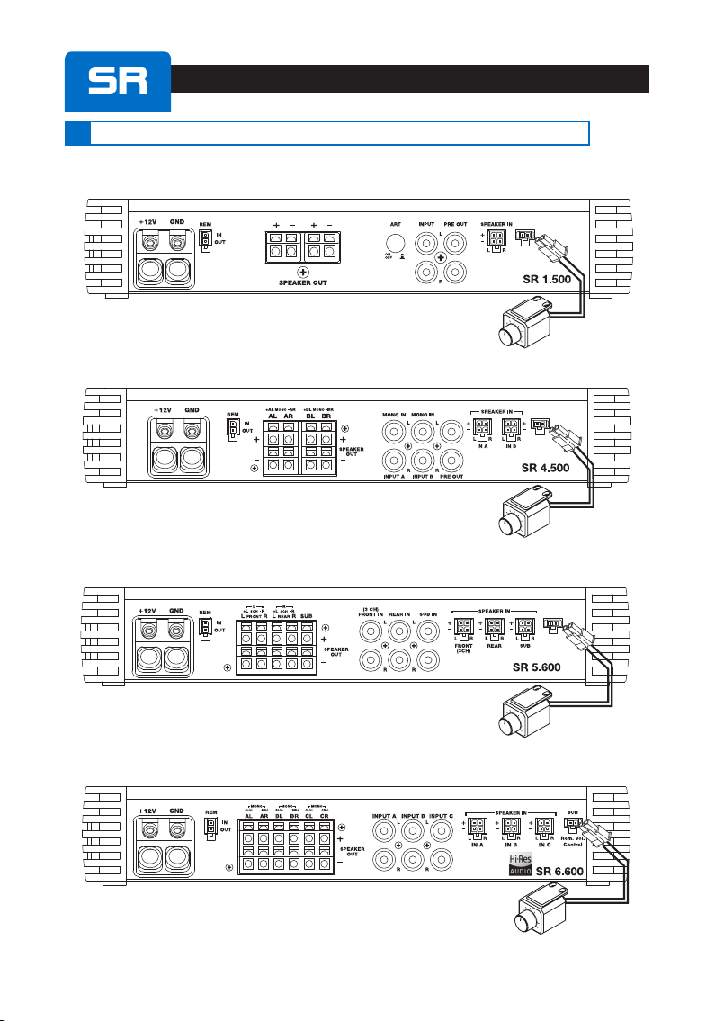
SR 1.500
Remote
IN / OUT cable
Remote
IN / OUT cable
Fuse 35A
Fuse 25A
Fuse 30A
SCREWS
4,2 x 55 mm
SCREWS
4,2 x 55 mm
SCREWS
4,2 x 55 mm
HEX KEY 2 mm
HEX KEY 3 mm
HEX KEY
2,5 mm
HEX KEY
3 mm
HEX KEY
2 mm
HEX KEY
2 mm
SCREWDRIVER
SCREWDRIVER
SCREWDRIVER
Speaker IN cable Speaker IN cable
x 1 x 1
x 2
x 2
x 1
x 4
x 4
x 4
x 1
x 1 x 1
x 1
x 1
x 1
x 1
x 1
x 1
x 1 x 2
SR 4.500
SR 4.300
PACKAGING CONTENTS
Remote
IN / OUT cable
Speaker IN cable
x 1
x 2
Ferrules x 2 Ferrules x 2
Ferrules x 2
Remote
IN / OUT cable
Fuse 25A
SCREWS
4,2 x 55 mm
HEX KEY
3 mm SCREWDRIVER
HEX KEY
2 mm
Speaker IN cable
x 1
x 2
x 4
x 1
x 1
x 3
SR 5.600
Ferrules x 2
x 1
Remote
IN / OUT cable
Fuse 30A
SCREWS
4,2 x 55 mm
HEX KEY
3 mm SCREWDRIVER
HEX KEY
2 mm
Speaker IN cable
x 1
x 2
x 4
x 1
x 1
x 3
SR 6.600
Ferrules x 2
x 1
Adjustment
CONTROLS
Not
AVAILABLE :: Set-up
CONTROLS
:
/Не е наличен /無法使用無法使用 /不提供不提供 /Nije dostupno /Není dostupný /Ikke tilgængelig /Niet beschikbaar /EI ole saadaval /Ei saatavilla /
Indisponible /Nicht verfügbar /Μη διαθεσιμο / /Nem elérhető /Tidak disediakan / Non disponibile /なしなし /사용할 수 없음사용할 수 없음 /Nav pieejams /NėraNėra
/Ikke tilgjengelig // Niedostępny /Não disponível /Indisponibil /Недоступно /Nie je k dispozícii /Ni na voljo /No disponible /Ej tillgänglig /
ไม่มีไม่มี /Kullanilmiyor
/Контролни елементи на
монтажа /設定控制 設定控制 /设置控制器设置控制器 /Kontrole postavljanja /
Nastavení ovládacích prvků / Opsætning af styreknapper /
Controles instellen /Seadistamisnupud /Asetussäätimet
/Contrôles de conguration /Einrichtungssteuerung /
Στοιχεια eλεγχου //Beállító kezelőszervek
/Kontrol pengaturan /Controlli di congurazione /設設
定用コントロール定用コントロール /설정 제어설정 제어 / Lestatījumu taustiņi /
Sąrankos valdikliaiSąrankos valdikliai /Oppsettkontroller /
/ Regulatory nastawcze /Controlos de conguração /
Comenzi congurare /Управление настройками /
Kontrolky nastavenia /Gumbi za nastavljanje /Controles
de conguración /Inställningsreglage /ปุ่มควบคุมการตั้งค่ปุ่มควบคุมการตั้งค่ /
Kurulum kontrolleri
/Контролни бутони за настройване
/調整控制調整控制 /调节控制器调节控制器 /Kontrole podešavanja /Ovládací
prvky /Reguleerimisnupud / Aanpassing controle /
Reguleerimise juhtnupud /Säädön ohjaukset /Contrôles
d’ajustement /Einstellungssteuerung /Στοιχεια ρυθμισης
// Szabályozó kezelőszervek /Kontrol
penyesuaian /Controlli di settaggio /調整調整 用コントロール用コントロール
/조정 제어조정 제어 /Regulēšanas taustiņi /Reguliavimo valdikliai
/Justeringskontroller //Pokrętła regulacyjne
/Controlos de regulação /Comenzi reglare /Управление
регулировками /Kontrolky úpravy /Gumbi za prilagoditev /
Controles de ajuste /Justeringsreglage /ปุ่มควบคุมการปรับปุ่มควบคุมการปรับ
เปลี่ยนค่าเปลี่ยนค่า /Ayar kontrolleri

User’s Manual
3
Index
1. PRECAUTIONS........................................................................................................................................................................................ 08
2. INSTALLATION AND SIZES................................................................................................................................................................. 42
3. CABLE SIZE CALCULATION TABLES. 1: POWER SUPPLY / 2: SPEAKERS........................................................................... 42
4. POWER SUPPLY and REMOTE IN CONNECTION / FUSE REPLACEMENT............................................................................ 43
5. SUBWOOFER REMOTE VOLUME CONTROL: VCR-S2 INSTALLATION.................................................................................. 44
6. PRE IN / SPEAKER IN / PRE OUT ......................................................................................................................................................45
7. AUTO TURN-ON BY SPEAKER IN (without REMOTE IN) .......................................................................................................... 50
8. INSTALLATION EXAMPLES:
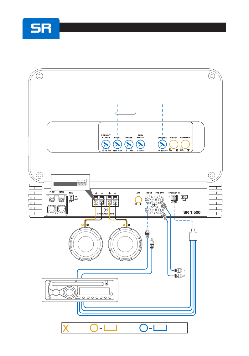
SR 1.500:
(1CH) FILTERED SUBWOOFER.................................................................................................................................... 54
(1CH)FILTERED2x2ΩSUBWOOFER ....................................................................................................................... 55
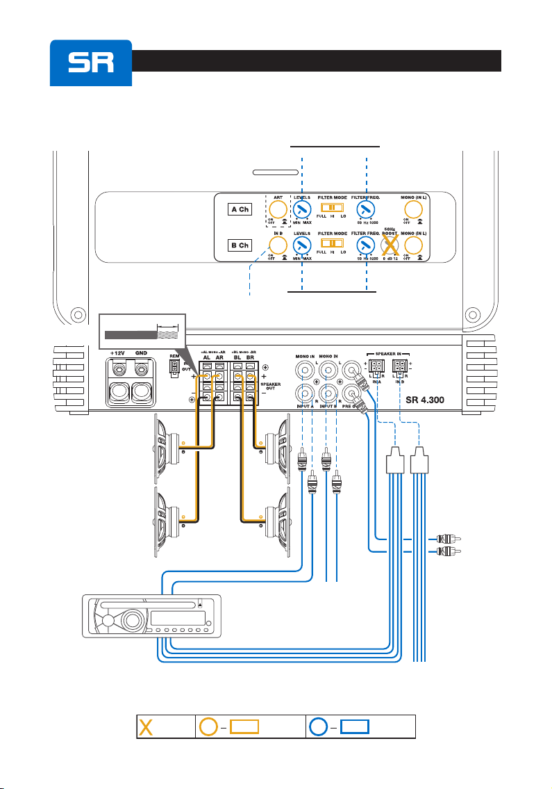
SR4.300 / SR 4.500:
(4CH) A Ch + B Ch ........................................................................................................................................................... 56
(4CH) WOOFER + MID/HI.............................................................................................................................................. 58
(3CH) FRONT + SUB....................................................................................................................................................... 59
(2CH) BRIDGE LEFT + RIGHT ...................................................................................................................................... 61
SR 5.600:
(5CH) FRONT + REAR + SUB ....................................................................................................................................... 62
(5CH) 2 WAY FRONT + SUB.......................................................................................................................................... 63
(3CH) FRONT + SUB....................................................................................................................................................... 64
SR 6.600:
(6CH) 3 WAY FRONT ...................................................................................................................................................... 65
(5CH) FRONT + REAR + SUB ....................................................................................................................................... 66
(3CH) FRONT + SUB....................................................................................................................................................... 67
9. BLOCK DIAGRAMS
SR1.500: .............................................................................................................................................................................................68
SR 4.300 ............................................................................................................................................................................................. 69
SR 4.500 ............................................................................................................................................................................................. 70
SR 5.600 ............................................................................................................................................................................................. 71
SR 6.600 ............................................................................................................................................................................................. 72
10. TECHNICAL SPECIFICATIONS
SR 1.500:............................................................................................................................................................................................. 73
SR 4.300 ............................................................................................................................................................................................. 73
SR 4.500 ..............................................................................................................................................................................................74
SR 5.600:..............................................................................................................................................................................................74
SR 6.600 ............................................................................................................................................................................................. 75
1. ПРЕДУПРЕЖДЕНИЯ.
2. РАЗМЕРИ.
3. ТАБЛИЦИ ЗА ИЗЧИСЛЯВАНЕ РАЗМЕРИТЕ НА
КАБЕЛИТЕ. № 1: ЗА ЕЛЕКТРОЗАХРАНВАНЕТО
№ 2: ВИСОКОГОВОРИТЕЛИТЕ.
4. ЕЛЕКТРОЗАХРАНВАНЕ И ВКЛЮЧВАНЕ НА
ДИСТАНЦИОНЕН ВХОДЯЩ СИГНАЛ Б
ПОДМЯНА НА БУШОНА.
5.
ДИСТАНЦИОННО УПРАВЛЕНИЕ НА СИЛАТА НА
ЗВУКА НА СУБ-УУФЕРА: МОНТАЖ НА „VCR-S2”.
6. ВХОД (PRE IN) / ВХОД ВИСОКОГОВОРИТЕЛ
(SPEAKER IN) / ИЗХОД (PRE OUT).
7. АВТОМАТИЧНО ВКЛЮЧВАНЕ ЧРЕЗ „ВХОД
ВИСОКОГОВОРИТЕЛ” (SPEAKER IN) (БЕЗ
ДИСТАНЦИОНЕН ВХОД „REMOTE IN”).
8. ПРИМЕРНИ МОНТАЖНИ РЕШЕНИЯ.
9. БЛОК-ДИАГРАМИ.
10.ТЕХНИЧЕСКИ СПЕЦИФИКАЦИИ.
ИНДЕКС Български
VCR-S2VCR-S2

User’s Manual
16
English /English
Before installing the components, please carefully read all of the instructions contained in this manual. It is advisable to carefully
follow the highlighted instructions. Failure to respect these instructions may cause unintentional harm or damage to the
components.
SAFETY CONSIDERATIONS
1. Makesureyourcarhas12VDCvoltagenegativegroundelectricsystem.
2. Checkyouralternatorandbatteryconditiontoensuretheycanhandletheincreasedconsumption.
3. Donotcarryoutanyinstallationinsidetheenginecompartmentorexposedtowater,excessivehumidity,dustordirt.
4. Neverruncablesoutsidethevehicleorinstalltheamplifiernexttoelectronicgearcases.
5. Installtheamplifierinthevehiclepartswheretemperatureisbetween0°C(32°F)and55°C(131°F).Lettheamplifierouterprofilebeatleast5cm(2”)far
frompossiblewalls.Theremustbegoodaircirculationwheretheamplifierisinstalled.Ifyoucovertheheatsink,theamplifiergoesinprotection.
6. Theamplifiercanreachtemperaturesofaround80°C(176°F).Makesureitisnotdangerouslyhotbeforetouchingit.
7. Periodicallycleantheamplifierwithoutusingaggressivesolventsthatmightdamageit.Don’tusecompressedair,sinceitwouldpushsolidparts
intheamplifiers.Dampenapieceofclothwithwaterandsoap,wringitandcleantheamplifier.Thenuseapieceofclothdampenedwithwateronly;
eventuallycleantheamplifierwithadrypieceofcloth.
8. Makesurethelocationyouchoseforthecomponentsdoesnotaffectthecorrectfunctioningofthevehiclemechanicalandelectricaldevices.
9. Makesurepowercableisnotshortcircuitedduringinstallationandconnectionwiththebattery.
10. Useextremecautionwhencuttingordrillingthecarplate,checkingtherearenoelectricalwiringorstructuralelementunderneath.
11.Whenpositioningthepowersupplycable,avoidtorunthewireoverorthroughsharpedgesorclosetomovingmechanicaldevices.Userubber
grommetstoprotectthewireifitrunsinaholeoftheplateorpropermaterialsifitisclosetoheat-generatingparts.
12.Makesureallthecablesareproperlysecuredallalongtheirlength.Also,makesuretheirouterprotectivejacketisflameresistantandself
extinguishing.Useaclampingscrewtosecurepositiveandnegativecablesjustclosetotheamplifierrespectivepowersupplyterminalblocks.
13. Choosethecablegaugeaccordingtotheamplifierpowerandtothesuggestionsyoucanfindhere.Usehighqualitycables,connectorsand
accessories,asyoucanfindintheConnectioncatalogue.
14. Pre-plantheconfigurationofyournewamplifierandthebestwiringroutestoeaseinstallation.
15.Inordertoavoidincidentaldamage,keeptheproductintheoriginalpackaginguntilyouarereadyforthefinalinstallation.
16.Alwayswearprotectiveeyewearwhenusingtools,assplintsorproductresiduemaybecomeairborne.
TYPICAL INSTALLATION SEQUENCE
If you have any questions please refer to the User’s Manual you can find available on www.audison.com or contact your AUDISON dealer or
AUDISON authorized service for assistance.
1. Beforeinstallingtheamplifierturnoffthesourceandallotherelectronicdevicesintheaudiosystemtopreventanydamages.
2. UsingacablewithadequateAWG(seechart:PowerSupplyCable),runthepowerwirefromthebatterylocationtotheamplifiermountinglocation.
3. Connectthepowersupplywiththecorrectpolarity.connect(+)terminaltothecablecomingfromthebatteryand(-)terminaltothecarchassis.
4. Putaninsulatedfuseholder40cmmaxfarfromthebatterypositiveterminal;connectoneendofthepowercabletoitaftertheotherendtothe
amplifier.Donotmountthefuse.
5. Togroundthedevice(-)intherightway,useascrewinthevehiclechassis;scrapeallpaintorgreasefromthemetalifnecessary,checkingwith
atesterthatthereiscontinuitybetweenthebatterynegativeterminal(-)andthefixingpoint.Ifpossible,connectallcomponentstothesame
groundpoint;thissolutionrejectsmostnoisewhichcanbegeneratedduringtheaudioreproduction.
6. Routeallsignalcablesclosetogetherandawayfrompowercables.
7. ConnecttheRCAinputcables,theappliedsignalmustbebetween0.2VRMSand5VRMS.(SR 6.600: 0.32 VRMS - 8 VRMS)
8. Connectthehighlevelinputsusingtheproperplug.Appliedsignalmustbebetween0.8VRMSand20VRMS.(SR 6.600: 1.6 VRMS - 40 VRMS)
Don’tuseitifyouarealreadyusingPreInpreamplifiedconnection.
9. Connectthespeakeroutputusing10AWGmaxspeakercable.
10.Don’tconnect(-)Land(-)Rspeakeroutputstogether.Ifyouuseanexternalstereocrossover,makesurethatitsnegativepolesarenotconnectedtogether.
11.Theamplifierturnsonbyconnectingtheremoteturnonterminal(REMOTEIN)tothesourcespecificoutput.Theamplifierturnsonautomatically,
withoutremotesignal,alsoifusinghighlevelinputs(SpeakerIN)bysettingthe“AUTOTURNON”switchtopositionON.
12. TheLEDonthetoppanellightsupblueindicatingthattheproductison.TheLEDlightsuprediftheoutputsgoonoverload,ifthethermalprotection
istriggered,ifthespeakercablesshortcircuitwiththevehiclechassisandiftheamplifierismalfunctioning.
13.Thefuse/sis/arelocatednearthepowersupplyandspeakerterminals.Toreplace,removethefuse/sfromthehousing.Alwaysreplacethefuse
ofthesamerating.
14.Secureallauxiliarydevicesyoubuilttoinstallthecomponentstothevehiclestructure;thisinsuresstabilityandsafetywhiledriving.Theamplifier
detachmentwhiledrivingcanseriouslydamagethepeopleinthevehicleandothercars.
15.Wheninstallationisover,checkthesystem’swiringandmakesureallconnectionsweredoneintherightway.
16.Putthefuseintothefuseholder.Thefusevaluewillhavetobe30%higherthantheamplifierbuilt-inone.Incasethecablesuppliesseveral
amplifiers,thefusevaluewillhavetobe30%higherthanthesumofthevaluesofallotherfusesintheamplifiers.
17.Listeninglevelcalibrationismadebyadjustingthesourcevolumeupto3/4ofitsmaximumlevel;then,adjusttheamplifierlevelsuntilyouheardistortion.
18. WarrantyCertificate:pleasecheckouttheAUDISONwebsiteforfurtherinformation.
SAFE SOUND
USE COMMON SENSE AND PRACTICE SAFE SOUND. PLEASE REMEMBER THAT LONG EXPOSURE TO EXCESSIVELY HIGH SOUND PRESSURE
LEVELS MAY DAMAGE YOUR HEARING. SAFETY MUST BE AT THE FOREFRONT WHILE DRIVING
Information on electrical and electronic equipment waste (for those European countries which organize the separate collection of waste)
ProductswhicharemarkedwithawheeledbinwithanXthroughitcannotbedisposedoftogetherwithordinarydomesticwaste.Theseelectricalandelectronicproducts
mustberecycledinproperfacilities,capableofmanagingthedisposaloftheseproductsandcomponents.Inordertoknowwhereandhowtodelivertheseproductstothe
nearestrecycling/disposalsitepleasecontactyourlocalmunicipaloffice.Recyclinganddisposingofwasteinaproperwaycontributestotheprotectionoftheenvironment
andtopreventharmfuleffectsonhealth.
1PRECAUTIONS

User’s Manual
42
1: Power supply cable 2: Speakers cable
Applied power
Cable diameter
Connection length
*Current Draw I (A)
Cable Length (m)
B
D C
A
E
A B C DE
SR 1.500 264 234 155 135 47,5 mm
10.39 9.21 6.1 5.31 1.87 in.
SR 4.300 190 160 155 135 47,5 mm
7.48 6.3 6.1 5.31 1.87 in.
SR 4.500 264 234 155 135 47,5 mm
10.39 9.21 6.1 5.31 1.87 in.
SR 5.600 294 264 155 135 47,5 mm
11.57 10.39 6.1 5.31 1.87 in.
SR 6.600 314 284 155 135 47.5 mm
12.36 11.18 6.1 5.31 1.87 in.
2INSTALLATION AND SIZES
3CABLE SIZE CALCULATION TABLES:
1: Power supply cable / 2: Speakers cable.

User’s Manual
43
APPLY A FUSE CLOSE
TO BATTERY
POSITIVE POLE
TO PROTECT
BATTERY CABLE
REMOTE
REMOTE
OUT
SOURCE
BATTERY
12 V FUSE
GND
GND
WARNING
MAX 20 cm / 7.9 in.
BATTERY
12 V
GND
GND
FUSE
SR 1.500 2 x 35A
SR 4.300 1 x 30A
SR 4.500 2 x 25A
SR 5.600 2 x 25A
SR 6.600 2 x 30A
BATTERY
12 V
FUSE HOLDER
GND GND
GND
4POWER SUPPLY and REMOTE IN CONNECTION / FUSE REPLACEMENT
Rem OUT
Rem IN
REMOTE CABLE CONNECTION
FUSE
REPLACEMENT
WARNING:
Firmlypresscontacts
ofeachfuseintro
theirfuse-holderclips.
MULTIPLE POWER SUPPLY CONNECTION
AMP 1
AMP 1
AMP 2
AMP 2
POSITIVE
AWG
AWG
NEGATIVE
15 mm / 0.6 in.
15 mm / 0.6 in.
POWER SUPPLY
Ferrules
AWG
SR 1.500 4
SR 4.300 6
SR 4.500 4
SR 5.600 4
SR 6.600 4
User’s Manual
44
VCR-S2
(Active only SUB Ch)
SUB
Rem. Vol.
Control
REMOTE
VOLUME
CONTROL OPTIONAL
MAX
REMOTE
VOLUME
CONTROL OPTIONAL
MAX
VCR-S2
(Active only C Ch)
SUB
Rem. Vol.
Control
- B Ch -
REMOTE
VOLUME
CONTROL OPTIONAL
MAX
VCR-S2
(Active only on B Ch)
SUB
Rem. Vol.
Control
REMOTE
VOLUME
CONTROL OPTIONAL
VCR-S2
MAX
SR 1.500
SR 4.500
SR 5.600
SR 6.600
5SUBWOOFER REMOTE VOLUME CONTROL: VCR-S2 INSTALLATION

User’s Manual
45
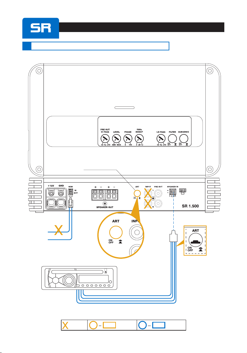
SUB
Rem. Vol.
Control
LEVELS (INPUT SENSITIVITY)
0.2 V
(Max)
5 V
(Min)
0°
180°
t
0
PHASE
AMP OUT
Hz
FILTER OFF
500
Hz
25050
FILTER ON
LO-PASS @ 24 dB/Oct.
BOOST - 50 Hz
+ 12
0Hz50
dB
SUBSONIC AMP OUT
Hz
25 Hz @ 24 dB/Oct.
25 500
PRE OUT
Hz
HI-PASS @ 12 dB/Oct.
50 250
SR 1.500
PRE
OUT
SPEAKER
IN
HI-LEVEL OUT
PRE OUT
PRE IN
SOURCE
USE PRE-IN OR
SPEAKER IN:
NOT BOTH
Adjustment
CONTROLS
Not
AVAILABLE :: Set-up
CONTROLS
:
R
L
L
L
R
R
POWER ON
LEDBlue
LED Red
CHECK
6PRE IN / SPEAKER IN / PRE OUT
graygray/black
whitewhite/black
FRONT VIEW
gray
gray/black
white
white/black
Wire size: 20 AWG
320mm / 12.6 in

User’s Manual
46
SR 4.300 / SR 4.500
SUB
Rem. Vol.
Control
- B Ch -
A Ch / B Ch FILTER MODE
AMP OUT
FULL RANGE
20k Hz
PASS MODE
FULL HI LO PASS MODE
FULL HI LO
AMP OUT
HI-PASS @ 12 dB/Oct.
Hz
50
3,2k PASS MODE
FULL HI LO
AMP OUT
LO-PASS @ 12 dB/Oct.
Hz50 3,2k
BOOST - 50 Hz
+ 12
0Hz50
dB
LEVELS (INPUT SENSITIVITY)
0.2 V
(Max)
5 V
(Min)
PRE OUT
SPEAKER IN
A CH
SPEAKER IN
B CH
HI-LEVEL OUT
PRE OUT
PRE IN
A CH
PRE IN
B CH
Adjustment
CONTROLS
Not
AVAILABLE :: Set-up
CONTROLS
:
FOR EACH INPUT
(A CH - B CH )
USE PRE-IN
OR SPEAKER IN
NOT BOTH
L
L L
R
R
R R
L
SOURCE
OFF ON
Ifusing
INPUT A
only,select:
Ifusing
INPUT B
select:
LED Red
CHECK
POWER ON
LEDBlue
SR 4300
not available
graygray/black
whitewhite/black
FRONT VIEW
gray
gray/black
white
white/black
Wire size: 20 AWG
320mm / 12.6 in
User’s Manual
47
If using REAR IN
select:
If using FRONT INPUT
only, select:
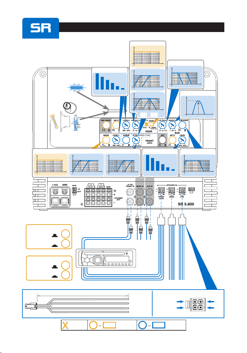
SR 5.600
Mode5Ch
SUB
Rem. Vol.
Control
LEVELS (INPUT SENSITIVITY)
0.2 V
(Max)
5 V
(Min) BOOST - 50 Hz
+ 12
0 Hz50
dB
LEVELS (INPUT SENSITIVITY)
0.2 V
(Max)
5 V
(Min)
FULL RANGE
20k Hz Hz
HI-PASS @ 12 dB/Oct.
50 500
x1
Hz
HI-PASS @ 12 dB/Oct.
500 5k
x10
FRONT MODE SUBSONIC
Hz
25 Hz @ 24 dB/Oct.
25
SUB
Hz
LO-PASS @ 24 dB/Oct.
50 500
REAR MODE
Hz
HI-PASS @ 12 dB/Oct.
50 500
FULL RANGE
20k Hz
Hz
BAND @ 12 dB/Oct.
50 500 500 5000
HI-PASS
Rear LO-PASS
Front
SPEAKER IN
FRONT
SPEAKER IN
REAR
SPEAKER IN
SUB
HI-LEVEL OUT
PRE OUT
PRE IN
FRONT PRE IN
REAR PRE IN
SUB
FOR EACH INPUT
(FRONT - REAR -SUB )
USE PRE-IN
OR SPEAKER IN
NOT BOTH
L
L L L
R
R
R R R
L
SOURCE
*
****
****
**
5 CH
POWER ON
LEDBlue
LED Red
CHECK
SUB INPUT
OFF
If using FRONT INPUT
only, select:
ON
If using SUB INPUT
select:
**NOTE
REAR INPUT
ON
*NOTE
OFF
Adjustment
CONTROLS
Not
AVAILABLE :: Set-up
CONTROLS
:
graygray/black
whitewhite/black
FRONT VIEW
gray
gray/black
white
white/black
Wire size: 20 AWG
320mm / 12.6 in

User’s Manual
48
SR 5.600
Mode3Ch
SUB
Rem. Vol.
Control
LEVELS (INPUT SENSITIVITY)
0.2 V
(Max)
5 V
(Min)
BOOST - 50 Hz
+ 12
0Hz50
dB
LEVELS (INPUT SENSITIVITY)
0.2 V
(Max)
5 V
(Min)
FULL RANGE
20k Hz Hz
HI- PASS @ 12 dB/Oct.
50 500
x1
Hz
HI- PASS @ 12 dB/Oct.
500 5k
x10
FRONT MODE
SUBSONIC
Hz
25 Hz @ 24 dB/Oct.
25
SUB
Hz
LO-PASS @ 24 dB/Oct.
50 500
SPEAKER IN
FRONT
SPEAKER IN
SUB
HI-LEVEL OUT
PRE OUT
PRE IN
FRONT
PRE IN
SUB
FOR EACH INPUT
(FRONT - SUB )
USE PRE-IN
OR SPEAKER IN
NOT BOTH
L
L L
R
R
R R
L
SOURCE
*
**
3 CH
POWER ON
LEDBlue
LED Red
CHECK
SUB INPUT
OFF
If using FRONT INPUT
only, select:
ON
If using SUB INPUT
select:
*NOTE
WARNING: Using3CHmodeREARINPUT
isnotavailable
Adjustment
CONTROLS
Not
AVAILABLE :: Set-up
CONTROLS
:
graygray/black
whitewhite/black
FRONT VIEW
gray
gray/black
white
white/black
Wire size: 20 AWG
320mm / 12.6 in
User’s Manual
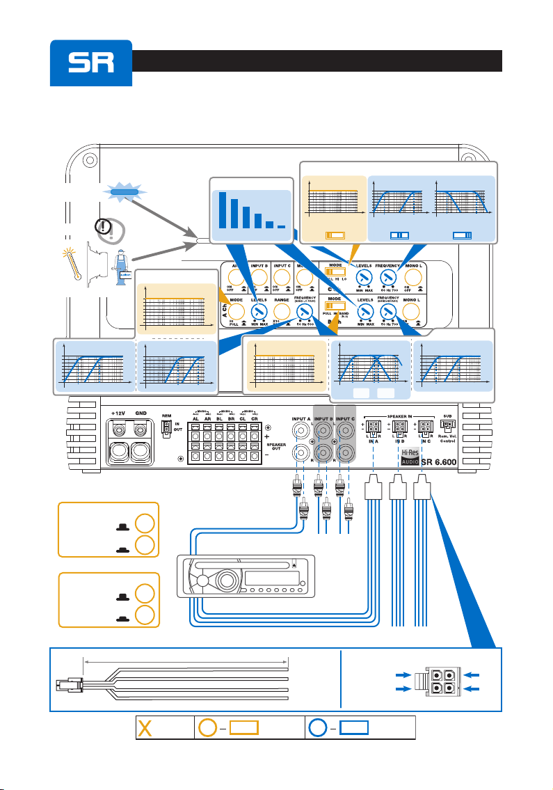
49
LEVELS (INPUT SENSITIVITY)
0.32 V
(Max)
8 V
(Min)
FULL RANGE
40k Hz
Hz
HI- PASS @ 12 dB/Oct.
50 500
x1
Hz
HI- PASS @ 12 dB/Oct.
50 700
x1
Hz
HI- PASS @ 12 dB/Oct.
500 5k
x10
A Ch MODE
FULL RANGE
40k Hz
B Ch MODE
BAND @ 12 dB/Oct.
50 500 700 5000
HI-PASS
B Ch LO-PASS
A Ch
C Ch FILTER MODE
AMP OUT
FULL RANGE
40k Hz
PASS MODE
FULL HI LO PASS MODE
FULL HI LO
AMP OUT
HI-PASS @ 12 dB/Oct.
Hz
50
700 PASS MODE
FULL HI LO
AMP OUT
LO-PASS @ 12 dB/Oct.
Hz50 700
Hz
SR 6.600
******
Adjustment
CONTROLS
Not
AVAILABLE :: Set-up
CONTROLS
:
graygray/black
whitewhite/black
FRONT VIEW
gray
gray/black
white
white/black
Wire size: 20 AWG
320mm / 12.6 in
POWER ON
LEDBlue
LED Red
CHECK
INPUT C
OFF
If using INPUT A
only, select:
ON
If using INPUT C
select:
**NOTE
INPUT B
If using INPUT B
select: ON
*NOTE
If using INPUT A
only, select: OFF
SPEAKER IN
A Ch
SPEAKER IN
B Ch
SPEAKER IN
C Ch
HI-LEVEL OUT
PRE OUT
PRE IN
A Ch PRE IN
B CH PRE IN
C Ch
FOR EACH INPUT
(A Ch - B Ch - C Ch )
USE PRE-IN
OR SPEAKER IN
NOT BOTH
L
R
R
L
SOURCE
User’s Manual
50
SUB
Rem. Vol.
Control
REMOTE IN
REMOTE OUT
Available
SR 1.500
SPEAKER
IN
ART (AUTO TURN ON)
enable SPEAKER IN
L
L
R
R
ON
ON
SOURCE
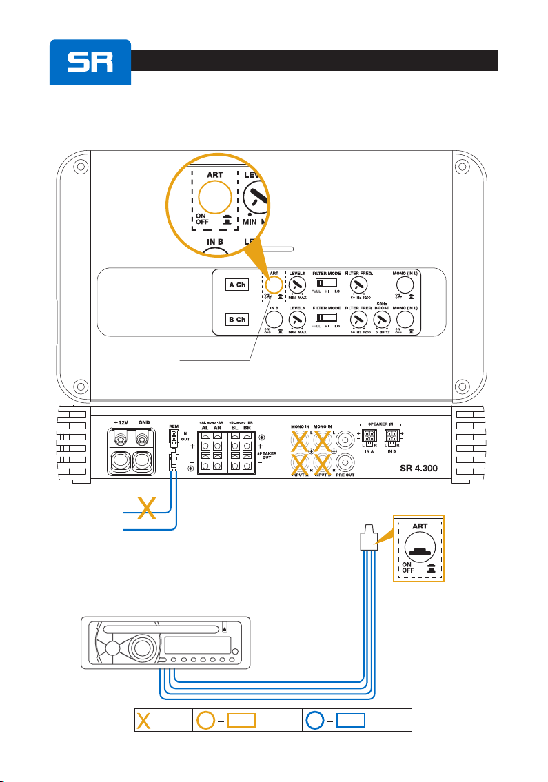
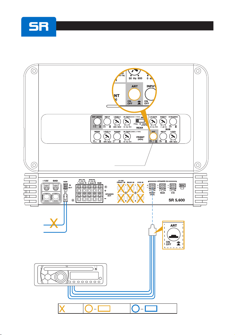
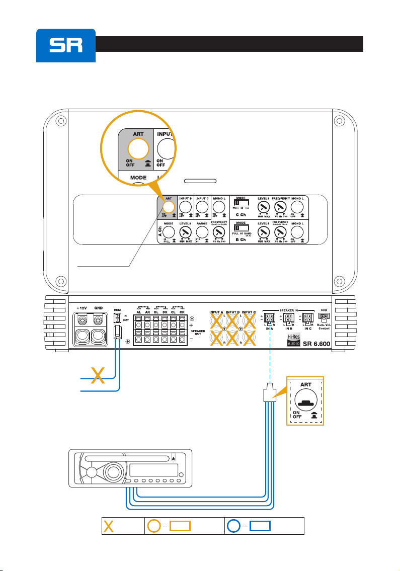
7AUTO TURN ON BY SPEAKER IN (without REMOTE IN)
Adjustment
CONTROLS
Not
AVAILABLE :: Set-up
CONTROLS
:
User’s Manual
51
SR 4.300 / SR 4.500
REMOTE IN
REMOTE OUT
Available
ON
SOURCE
L
L
R
R
ART (AUTO TURN ON)
enable SPEAKER IN
ON
SPEAKER IN
IN A
Adjustment
CONTROLS
Not
AVAILABLE :: Set-up
CONTROLS
:
User’s Manual
52
SUB
Rem. Vol.
Control
REMOTE IN
REMOTE OUT
Available
ON
ON
SR 5.600
L
L
R
R
SOURCE
ART (AUTO TURN ON)
enable SPEAKER IN
SPEAKER IN
FRONT
Adjustment
CONTROLS
Not
AVAILABLE :: Set-up
CONTROLS
:
User’s Manual
53
REMOTE IN
REMOTE OUT
Available
SR 6.600
L
L
R
R
SOURCE
SPEAKER IN
A Ch
Adjustment
CONTROLS
Not
AVAILABLE :: Set-up
CONTROLS
:
ON
ON
ART (AUTO TURN ON)
enable SPEAKER IN
User’s Manual
54
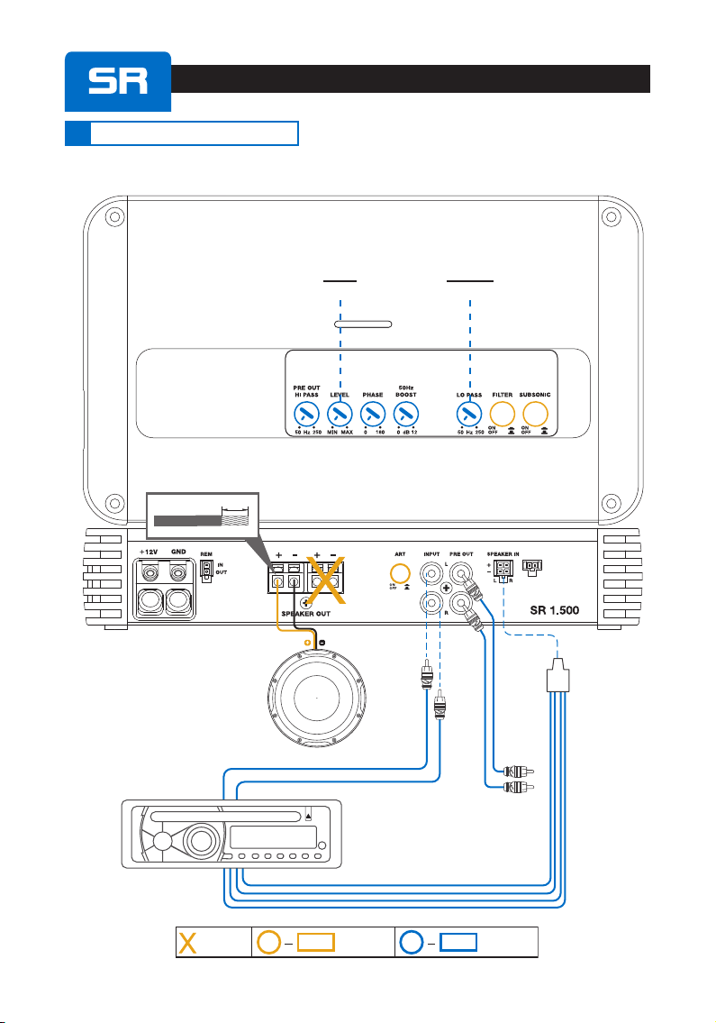
SR 1.500
SUB
Rem. Vol.
Control
INPUT SPEAKER
IN
to OTHER
AMPLIFIERS
USE PRE-IN
OR SPEAKER IN:
NOT BOTH
SUBWOOFER(min1Ω)
L
L
L
R
R
R
SOURCE
1CH: FILTERED SUBWOOFER
ON
SUB
LEVEL SUB
LO PASS
8INSTALLATION EXAMPLES
Adjustment
CONTROLS
Not
AVAILABLE :: Set-up
CONTROLS
:
SPEAKERS CABLE
16 mm/ 0.62 in.
User’s Manual
55
SR 1.500
SUB
Rem. Vol.
Control
INPUT
L
L
SOURCE
R
R
1CH: FILTERED 2 X 2Ω SUBWOOFER
ON
SUB
LEVEL
to OTHER
AMPLIFIERS
SUB
LO PASS
SPEAKER
IN
USE PRE-IN
OR SPEAKER IN:
NOT BOTH
L R
Adjustment
CONTROLS
Not
AVAILABLE :: Set-up
CONTROLS
:
SUBWOOFERmin2Ω SUBWOOFERmin2Ω
SPEAKERS CABLE
16 mm/ 0.62 in.

User’s Manual
56
4CH: A Ch + B Ch
INPUTS: INPUT A
OUTPUTS
SR 4.300 / SR 4.500
OFF
OFF OFF
L
R R
R
R
R
L L
L
L
B Ch
LEVELS HI-PASS
A Ch
LEVELS HI-PASS
SPEAKER IN
IN A
A Ch
OUTPUTS
A Ch
INPUT
*COAXIAL
SPEAKERS
B Ch
OUTPUTS
HI
HI
SOURCE
* *
* *
to OTHER
AMPLIFIERS
USE PRE-IN
OR SPEAKER IN:
NOT BOTH
Adjustment
CONTROLS
Not
AVAILABLE :: Set-up
CONTROLS
:
SPEAKERS CABLE
16 mm/ 0.62 in.
User’s Manual
57
OUTPUTS
UsingalsoB Ch:
SR 4.300 / SR 4.500
ON
OFF
OFF
L LR R
SPEAKER IN
IN A
SPEAKER IN
IN B
activate
B Ch
INPUT
SOURCE
R R
LL
A Ch
OUTPUTS
*COAXIAL
SPEAKERS
B Ch
OUTPUTS
* *
* *
to OTHER
AMPLIFIERS
4CH: A Ch + B Ch
L
L
R
R
USE PRE-IN
OR SPEAKER IN:
NOT BOTH
A Ch
INPUT
B Ch
INPUT
B Ch
LEVELS HI-PASS
A Ch
LEVELS HI-PASS
Adjustment
CONTROLS
Not
AVAILABLE :: Set-up
CONTROLS
:
SPEAKERS CABLE
16 mm/ 0.62 in.
This manual suits for next models
5
Table of contents
Other Audison Car Stereo System manuals


