Auditronics 220 Digital Audio Console User manual
220 Digital Audio Console
TECHNICAL MANUAL
March 2000

R-16 / Dec 1997
220 Digital Audio Console Technical Manual - 1st Edition220 Digital Audio Console Technical Manual - 1st Edition
220 Digital Audio Console Technical Manual - 1st Edition220 Digital Audio Console Technical Manual - 1st Edition
220 Digital Audio Console Technical Manual - 1st Edition
©2000 Auditronics® *
AUDITRONICS
600 Industrial Drive
New Bern, North Carolina 28562
252-638-7000
*a division of Wheatstone Corporation
220/ March 2000

AA
AA
ATTENTIONTTENTION
TTENTIONTTENTION
TTENTION
RR
RR
READEAD
EADEAD
EAD MM
MM
MEE
EE
E!!
!!
!
220 / March 2000
Attention!
This console contains static sensitive devices:
Normal precautions against static discharge should be observed when
handlingindividualmodules.Inparticular, modulesbeingpackedforshipping
for return or repair must be packed in special static protection bags before
packaging. Damage caused by static discharge may not be covered under
warranty.
Replacing Modules in a Powered-up Console:
While in an emergency situation it is possible to remove and insert modules
on a powered-up console, Auditronics does not recommend this procedure.
Whenever possible it is best to power down the console first before removing
or replacing modules.
However, if you find you must proceed with this operation, then be sure to
take the following precaution:
When re-inserting a module, take care to replug it squarely into its
mainframe connector socket, so all edgecard fingers make contact
simultaneously. In other words, the gold-plated bus connector fingers on the
bottom edge of the module's printed circuit board must be inserted squarely
(i.e., perpendicular) to the mating socket on the bottom pan of the console
mainframe. The intent is to prevent a situation where one of the module's
power pins makes significant contact before the others. (Naturally, this
same precaution must be taken when using extenders.)
Iftheaboveinstructionsarefollowedtheprocedureshouldberoutine;ifthey
are not, you could run the risk of damaging the console's logic chips.
Again, to avoid ANY possibility of this damage, whenever possible we
stronglyrecommendpoweringdowntheconsolebeforereplacinganymodules.
!

AA
AA
ATTENTIONTTENTION
TTENTIONTTENTION
TTENTION
RR
RR
READEAD
EADEAD
EAD MM
MM
MEE
EE
E!!
!!
!
220 / March 2000
Console Clock Battery Backup
Console Clock Display Card
To activate battery backup of the console’s clock simply pull out the yellow
strip from the clock display card, that is mounted on the inside of console
meterbridge, as shown on the picture below.

page Contents – 1
220 / Sep 2000
CONTENTS
220 Technical Manual
Table of Contents
Chapter 1 – Installation and Power
CountertopMounting................................................................. 1-2
Clearances.............................................................................................................. 1-2
System Ground .......................................................................... 1-2
Power Supply ............................................................................. 1-4
The PSC-D340 Power Supply ................................................................................ 1-5
Power Connector Pinout......................................................................................... 1-5
PSC-D340 Power Supply Schematic ...................................................................1-5A
Energizing ............................................................................................................... 1-6
Audio and Control Wiring.......................................................... 1-7
ConnectionProcedures .......................................................................................... 1-7
Digital Connections................................................................................................. 1-7
Analog Insert Points................................................................................................ 1-7
Unbalanced Connections (analog audio) ............................................................... 1-8
Hand Crimp Tool Wiring Instructions...................................................................... 1-9
Chapter 2 - Input Module
Module Overview........................................................................ 2-2
Internal Programming Options ................................................. 2-3
Insert Bypass .......................................................................................................... 2-3
Phantom Power ...................................................................................................... 2-3
Talkback.................................................................................................................. 2-3
VDT Programming Options ....................................................... 2-4
Hook-ups..................................................................................... 2-4
Microphone Inputs ..................................................................... 2-4
Audio Connections.................................................................................................. 2-4
Control Connections ............................................................................................... 2-4
Remote ON & OFF ................................................................................................. 2-5
Cough ..................................................................................................................... 2-5
Talkback to Control Room ...................................................................................... 2-5
On Tally................................................................................................................... 2-5
Off Tally................................................................................................................... 2-6
Tally B ..................................................................................................................... 2-6
Stereo Line Analog Inputs......................................................... 2-6
Audio Connections.................................................................................................. 2-6
Stereo Line Digital Inputs.......................................................... 2-6
Audio Connections.................................................................................................. 2-6
Control Connections ............................................................................................... 2-7
220 / Oct 2001

page Contents – 2
220 / Sep 2000
CONTENTS
Remote ON & OFF ................................................................................................... 2-7
External START & STOP ......................................................................................... 2-7
Ready........................................................................................................................ 2-8
Tally B ....................................................................................................................... 2-8
DB Connector Pinout Drawing
Mono Mic Inputs ....................................................................................................... 2-9
Stereo Line Analog Inputs ....................................................................................... 2-10
Stereo Line Digital Inputs ........................................................................................ 2-11
Mono-Mic Input Signal Flow Diagram ........................................2-12
Stereo Line Input Signal Flow Diagram .....................................2-13
Chapter 3 - Output Module
Module Overview...........................................................................3-2
CPU.................................................................................................3-3
DSP.................................................................................................3-4
Serial Interface ..............................................................................3-5
Using Serial Interface ............................................................................................... 3-5
Internal Programming Options ....................................................3-6
Global Settings ......................................................................................................... 3-6
RS-485/RS-232Select ............................................................................................. 3-7
RS-485 Termination.................................................................................................. 3-7
Hook-ups........................................................................................3-8
Analog Audio Outputs............................................................................................... 3-8
Digital Outputs .......................................................................................................... 3-8
Digital Control Ports.................................................................................................. 3-9
DB Connector Pinout Drawings
Analog and Digital Outputs...................................................................................... 3-10
Digital Control Ports................................................................................................. 3-11
Master Outputs Signal Flow Diagram ........................................3-12
CPU/DSP Signal Flow Diagram...................................................3-13
Chapter 4 - Control Room Module
Module Overview...........................................................................4-2
Internal Programming Options ....................................................4-3
Cue Interrupt............................................................................................................. 4-3
Cue Mute .................................................................................................................. 4-3
Hook-ups........................................................................................4-3
Upper DB-25 “A” Connector — Audio ...................................................................... 4-3
Upper DB-25 “A” Connector — Control.................................................................... 4-4
On-Air Tally......................................................................................................... 4-4
Lower DB-25 “B” Connector — Audio ...................................................................... 4-4
DB Connector Pinout Drawing.....................................................4-5
Control Room Monitor Signal Flow Diagram..............................4-6

page Contents – 3
220 / Sep 2000
CONTENTS
Chapter 5 - Studio Control Module
Module Overview...........................................................................5-2
Internal Programming Options ....................................................5-3
External Talkback Mute/Dim..................................................................................... 5-3
Studio Dim ................................................................................................................ 5-3
Hook-ups........................................................................................5-3
Upper DB-25 “A” Connector — Audio ...................................................................... 5-3
Upper DB-25 “A” Connector — Control.................................................................... 5-4
Tally 2 and Tally 3 ............................................................................................... 5-4
Lower DB-25 “B” Connector — Audio ...................................................................... 5-4
DB Connector Pinout Drawing.....................................................5-5
Studio Control Monitor Signal Flow Diagram.............................5-6
Chapter 6 - Virtual Dip Switch
Virtual Dip Switch Application Program .....................................6-2
Installation................................................................................................................. 6-2
Hooking up the computer ......................................................................................... 6-2
Running the program ................................................................................................ 6-3
Using the program .................................................................................................... 6-5
Input attenuation ....................................................................................................... 6-8
Advanced operation................................................................................................. 6-10
Ending the program ................................................................................................. 6-12
Serial Interface Cable DB Connectors Pinout Drawing ............6-13
Chapter 7 - Superphone Input Module
Module Overview...........................................................................7-2
Caller Set-Ups .......................................................................................................... 7-2
Automatic Features................................................................................................... 7-3
Inputs and Outputs ................................................................................................... 7-3
Internal Programming Options - Main PCB ................................7-4
External In................................................................................................................. 7-4
Cue Pre/Post ............................................................................................................ 7-4
Mutes ........................................................................................................................ 7-4
Timer Restart ............................................................................................................ 7-4
Tallies........................................................................................................................ 7-4
Cue Dropout.............................................................................................................. 7-5
Gain Trimpots ........................................................................................................... 7-5
Hook-ups........................................................................................7-5
Audio Connections (Upper DB-25 “A”) ..................................................................... 7-5
Audio and Control Connections (Lower DB-25 “B”) ................................................. 7-6
DB Connector Pinout Drawing.....................................................7-7
Superphone Module Signal Flow Diagram .................................7-8

page Contents – 4
220 / Sep 2000
CONTENTS
Chapter 8 - Line Preselector Module
Module Overview...........................................................................8-2
Internal Programming Options ....................................................8-2
Hook-ups........................................................................................8-3
Audio Inputs .............................................................................................................. 8-3
Outputs ..................................................................................................................... 8-3
DB Connector Pinout Drawing.....................................................8-4
Line Preselector Signal Flow Diagram........................................8-5
Chapter 9 - Tape Remote Module
Module Overview...........................................................................9-2
DB Connector Pinout Drawing
START/STOP Function Control I/O.......................................................................... 9-3
Full-Function Control I/O .......................................................................................... 9-4
Chapter 10 - Meterbridge
Overview .......................................................................................10-2
Replacement Parts.......................................................................10-2
Digital Timer .................................................................................10-3
Console Clock ..............................................................................10-3
Controls.................................................................................................................... 10-3
Setting the time........................................................................................................ 10-4
Battery Backup ........................................................................................................ 10-4
Operational Modes .................................................................................................. 10-4
Clock/Timer(CLK-220)
Schematic ................................................................................................................ 10-5
Load Sheet............................................................................................................... 10-6
Clock/Timer Display (CLD-220)
Schematic ................................................................................................................ 10-7
Load Sheet............................................................................................................... 10-8
Chapter 11 - I/O Schematic Drawings
Mono Mic ADC I/O Card Schematic (MMADC-220) .............................................. 11-2
Analog Stereo Line ADC I/O Card Schematic (SLADC-220)................................. 11-3
Digital Stereo Line SRC I/O Card Schematic (SRC-220) ...................................... 11-4
Output Module I/O Schematic (OMD-220) ............................................................. 11-5
Control Room Module I/O Schematic (CRD-220) .................................................. 11-7
Studio Control Module I/O Schematic (SCD-220).................................................. 11-9
Superphone Module I/O Schematic (SPD-220) .................................................... 11-11
Line Select Module I/O Schematic (LS-220) ......................................................... 11-13
Appendix
Replacement Parts List ............................................................... A-2
220 / Jun 2002

INSTALLATION and POWER
page 1 – 1
220 / March 2000
Installation and Power
Chapter Contents
CountertopMounting................................................................. 1-2
Clearances.......................................................................................................... 1-2
System Ground .......................................................................... 1-2
Power Supply ............................................................................. 1-4
The PSC-D340 Power Supply ............................................................................ 1-5
Power Connector Pinout..................................................................................... 1-5
PSC-D340 Power Supply Schematic ...............................................................1-5A
Failsafe Dual Redundant Supply........................................................................ 1-6
Energizing........................................................................................................... 1-6
Audio and Control Wiring.......................................................... 1-7
ConnectionProcedures ...................................................................................... 1-7
Digital Connections............................................................................................. 1-7
Analog Insert Points ........................................................................................... 1-7
Unbalanced Connections (analog audio) ........................................................... 1-8
Hand Crimp Tool Wiring Instructions.................................................................. 1-9
220 / Oct 2001

INSTALLATION and POWER
page 1 – 2
220 / March 2000
Installation and Power
CountertopMounting
The 220 digital audio console is designed for countertop drop-in
mounting. Console placement should avoid proximity to any electro-
magneticfields,suchaslargepowertransformers,motors,andfluores-
centlightingfixtures.Therequiredcut-outwidthis371/4”andcut-out
front-to-back dimension is 19”. The front of the console will extend
approximatelyoneinchforward ofthe cut-out.The console’swooden
sidepieces will extend about 7/8” on either side of the cut-out width.
Clearances
Note the two module extractor tools (black thumbwheel screws)
mounted in the front surface of console’s lower mainframe pan (just
above and to the left of the righthand headphone jack). These must be
removed before lowering the console into its cutout!
Once in place the console mainframe pan will extend approxi-
mately 5/8 inches below the countertop surface. Note the hinged
meterbridge will require 15” above the countertop surface to open
freely. When fully open the meterbridge will extend 5 1/2” behind the
rear line of the cut-out. When closed, the meterbridge will extend
2 1/4” behind this rear cut-out line and 8 1/8” above the countertop
surface.
Do not connect the 220 console to its power supply (and do not
connect the power supply to the AC power line) until instructed to do
so.
System Ground
The first step is to ground the console.
Note that as supplied from the factory, console rackmount power
supply common, audio ground, and the 220 mainframe are connected
togetherattheconsole,butareNOTconnectedtoelectricalgroundand
the chassis of the power supply. Safety requirements dictate that a
positiveconnectionfromtheconsolemainframetoelectricalgroundbe
!

I N S T A L L A T I O N a nd P OWER
page 1 – 3
220 / March 2000
CONSOLE
2-TRACK
MULTI-TRACK
AC BREAKER
BOX
DEVICE 1
DEVICE 2
DEVICE N
CONSOLE POWER SUPPLY
CONTROL ROOM POWER AMP
STUDIO POWER AMP
OTHER
POWER COMPANY
EARTH GROUND
HEAVY
(#4 or #6)
COPPER
WIRE
HIGH POWER
EQUIPMENT RACK
COPPER ROD
SOIL 3-wire ground or separate wire run from chassis
EFFECTS RACK
MIC PANEL
GND
TYPICAL SYSTEM
GROUNDING SCHEME
etc.
3–5 ft.
Tie the console ground lug
terminal strip to the system
earth ground. Tie every piece
of equipment in the entire
audio system to the console
ground lug terminal strip.
made in the completed installation. Use one of the grounding lugs on
the rear of the mainframe to establish your system ground. The
grounding lug terminal strip may be found at the rear of the console,
along the bottom edge of the mainframe pan directly under the
rightmost mainframe slots (to the lower left if you are looking at the rear
of the console).
The system ground serves two important purposes:
(1) It provides a zero signal reference point for the entire audio system;
(2) It assures safety from electrical shock.
There exist two terms that one encounters in a discussion of ground:
(A) EARTH GROUND, which is usually a heavy copper rod driven into the
soil adjacent to the building (around 6 feet down) or a connection to the copper
water pipes leading into the building. Either is acceptable (unless, of course,
the water pipe is made of plastic).
(B) THE POWER COMPANY EARTH CONDUCTOR that enters the
building at the power line breaker box; this conductor should be (and is often
by code) tied to the above-mentioned earth ground at one point. This point is
the SYSTEM EARTH GROUND.

INSTALLATION and POWER
page 1 – 4
220 / March 2000
TIE THE CONSOLE GROUND LUG TERMINAL STRIP TO THE
SYSTEMEARTHGROUND. TIEEVERYPIECEOFEQUIPMENTIN
THE ENTIRE AUDIO SYSTEM TO THE CONSOLE GROUND LUG
TERMINAL STRIP. If the system earth ground point is inaccessible, tie
the console ground terminal strip to the power company earth conductor
at the main breaker box (see drawing "Typical Grounding Scheme" on
previous page).
Each piece of equipment should be connected by its own ground wire
(usually the round third pin on the AC cord). This means that every AC
outlet must have a separate conductor run to the console ground lug
terminal strip; the outlets cannot be daisy-chained as is normally encoun-
tered in commercial and residential AC systems. Any equipment not
supplied with 3-wire AC cables must have individual ground wires (16
gauge or larger) connected to their chassis grounds and then run to the
console ground lug terminal strip.
Further Grounding Details
Check all equipment to be absolutely certain that each unit is power
transformer isolated from the AC mains to prevent safety hazards.
It is assumed that in each piece of audio equipment the audio ground
and the chassis are tied together at some point. Any piece of equipment
lacking a grounded chassis is likely to be prone to interference problems.
Locateallunbalancedaudio equipment inthesamerack if possible,to
minimize chassis ground potential differences. It may also be helpful to
insulateeachpieceofunbalancedequipmentfromitsmountingrailsinthe
rackbymeansofnylon10-32screwsandinsulatingwashersbetweenrails
and faceplates.
Once the system is properly grounded, proceed with the console
power supply installation and connection (next section).
Power Supply
The 220 console is powered by a Wheatstone Model PSC-D340
rackmount power supply. This heavy duty unit occupies three 19” wide
rack spaces (total height 5-1/4”). Convection cooled, it requires ample
ventilation space above and below it. Do not mount heat generating
devices in the same rack cabinet.
Notethepowersupplyshouldbemountedinanequipmentrackwithin
fifteen feet of the console (but no closer than 3 feet). Avoid locating any
highgainequipment(suchasphonopreamps,taperecorders,etc.)toonear
the rackmount supplies, to avoid magnetic interference into that equip-
ment.
220 / June 2001
Iffailsaferedundantsup-
plieshavebeenordered,
you will be installing two
units and an additional
rackmount panel.
INSTALLATION and POWER
page 1 – 5
220 / March 2000
Oncethesupplyis rackmounted, itshouldbeconnected to theconsole
usingthefactorysuppliedcable.Theconsole’spowersupplyconnectoris
locatedattherearoftheconsole,attherightendofthemeterbridgebottom
pan.Ifyouareusingonesupply,connectittotheconsoleconnector.Ifyou
are using two supplies (failsafe option), connect the long power supply
cabletothecenterconnectoroftherackmountfailsafepanel.Thenconnect
onesupplywithashort cabletoeitherofthe two remainingconnectorson
the failsafe panel and connect the second supply with a short cable to the
lastconnector.Notethatthepowersupplycable’s10-pinfemaleconnector
has to be rotated until its locating pins match the male connector on the
console. Do not force a connector on; it attaches easily when properly
aligned. Connect the cable first to the console, then to the rear of the
rackmount power supply.
Note each power supply is fitted with a 3-wire grounded AC cord that
shouldbe plugged intoa "clean"AC power source. Thatis, anAC source
that feeds only the control room audio gear. This source should be a
separatefeedfromthosepoweringlighting,air-conditioning,oranyother
non-audiomachinery. Thethird pin groundwire of theACsource should
be tied to the central system ground point. Note that while the AC power
cord ground wire terminates at the power supply chassis, it does NOT
connect to the 220 console common; the console itself must be grounded
separately. (See previous section, "System Ground".)
The power feed recom-
mended in the text is of-
teninstalledandreferred
to in studios as an “iso-
lated AC ground” outlet.
It is usually orange in
color.
220 / June 2001
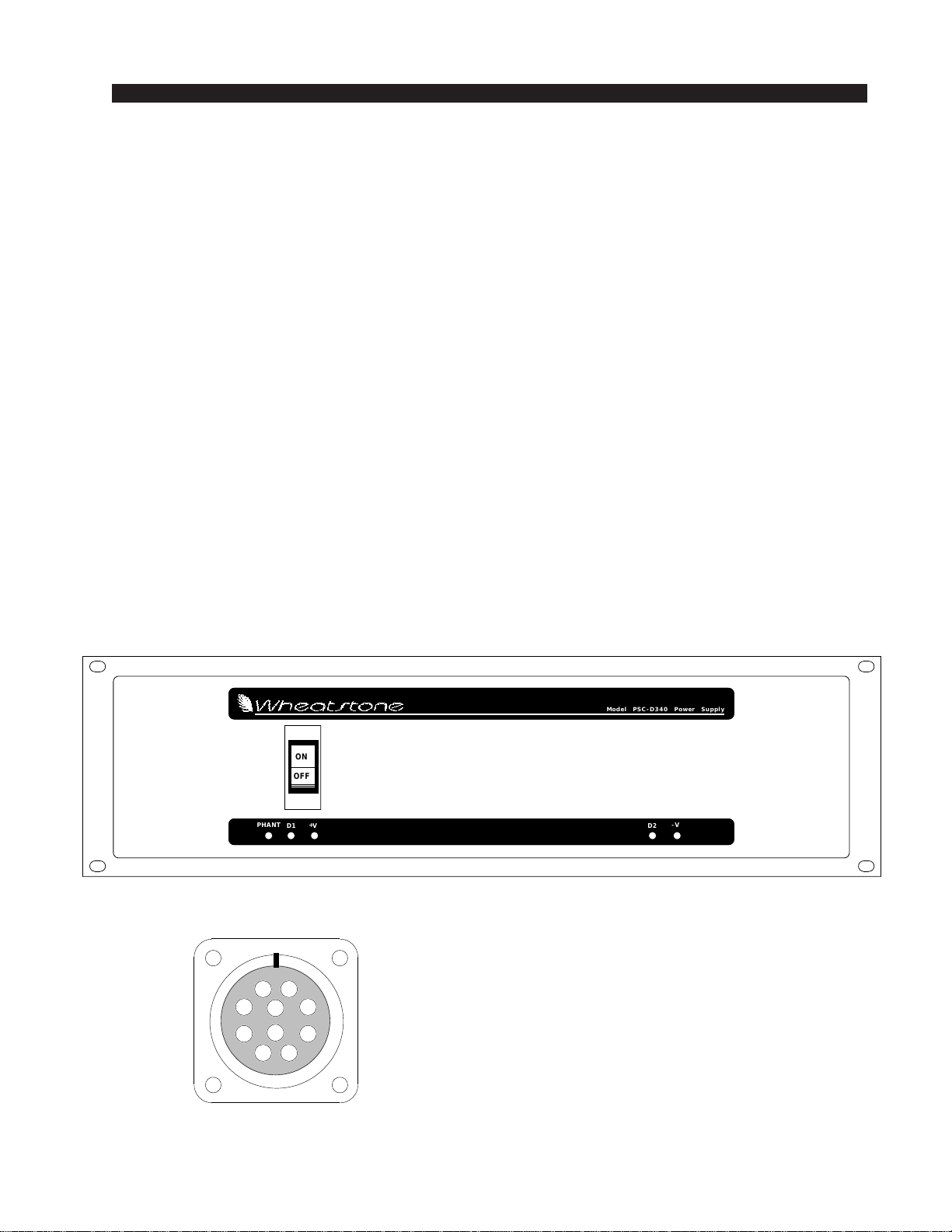
The PSC-D340 Power Supply
HA
ED
I
JB
C
G
F
TYPICAL POWER
CONNECTOR
(10-pin)
A :
B :
C :
D :
E :
F :
G :
H :
I :
J :
audio/phantom common
+V audio
-V audio
digital common
phantom power
digital common
+digital
+digital
n/c
n/c
ON
OFF
+VD1
PHANT
Model PSC-D340 Power Supply
D2
–
V
220 / June 2001

R1
330
.05
R2
.05
R7
Q1
1
23
LM1085
VIN
ADJ
OUT
3
2
1
Q3
LM1085
VIN
ADJ
OUT
1uF
C1
6A4
D1
C7
1uF
1uF
C2
C6
1uF
620
R6
R5
100
1N4002
D3
6A4
D2
R20
1.0K
R14
.05
R19
.05
LM1085
3
2
1
Q5
VIN
ADJ
OUT
1uF
C12
6A4
D14
1uF
C18
1uF
C13
1uF
C17
R15
620
R16
470
1N4002
D12
D13
6A4
R4
47
47
R17
1uF
C4
1uF
C15
WP1
=14V
DC
+
WP17
+7.5V
OUTPUT
TP4 -
WP18
TP2
WP15
WP12
TP4
+
7.5V
TEST
POINT
-
TP3
WP5
=23V
DC
+
WP24
-16V
OUTPUT
WP8 -
WP25
TP8
+
16V
TEST
POINT
-
TP7
NOT
INSTALLED DS5
+16V
LED
DS6
+7.5V
LED
DS3
NOT
INSTALLED
-16V
LED
DS4
+7.5V
LED
2200uF
C26
2200uF
C28
WP19
WP9
WP22
WP20
WP21
WP16
WP26
WP3
WP2
WP7
WP6
R1
1.0K
R2
.05
R7
.05
LM1085
3
2
1
Q1
VIN
ADJ
OUT
LM1085
Q3
1
23
VIN
ADJ
OUT
C1
1uF
D1
6A4
1uF
C7
50V
10000uF
C19
C2
1uF
1uF
C6
R6
620
R5
470
D3
1N4002
6A4
D2
R20
330
.05
R14
.05
R19
Q5
1
23
LM1085
VIN
ADJ
OUT
C12
1uF
D14
6A4
C18
1uF
C13
1uF
C17
1uF
R15
330
R16
100
D13
6A4
47
R4
C4
1uF
C15
1uF CR3 1
2
3
500
+7.5V
TRIM
WP1
=23V
DC
WP17
+
+16V
OUTPUT
TP4
WP18
-
TP1
TP2
WP15
WP12
TP4
+
16V
TEST
POINT
-
TP3
WP5
=14V
DC
WP24
+
+7.5V
OUTPUT
WP8
WP25
-
TP8
+
7.5V
TEST
POINT
-
TP7
DS5
+16V
LED
DS3
-16V
LED
DS4
+7.5V
LED
2200uF
C26
2200uF
C28
WP19
WP9
WP22
WP20
WP21
WP16
WP26
WP3
WP2
WP7
WP10
WP11
82V
82ZA2
V1
100V
470uF
C21
D4
1N4002
D7
1N4002
D5
1N4002
D6
1N4002
D10
1N4002
10K
CR2
3
2
1
+40V
TRIM
63V
10uF
C22 C11
10uF
63V
0.0047uF
C8
0.0047uF
C10
D8
1N4002
LM317
Q4
1
23
VIN
ADJ
OUT
220
R10
R9
470
R8
100K
D9
1N4002
SW1
PHANTOM
POWER ON
DIP SWITCH
1
2
3
4
D11
1N4002
WP23
+
+40V
OUTPUT
WP14
-
WP13
R11
10K
R12
10K
R13
10K
TP6
+
4OV
TEST
POINT
-
TP5
DS1
+40V
LED
DS2
NOT
INSTALLED
+40V
LED
TP1
F1
.4A
POLYSW
10uF
63V
C9
WP6
50V
10000uF
C23
Q7
3
2
1LM1085
VIN
ADJ
OUT
R17
47
D12
1N4002
NOT
INSTALLED
DS6
+7.5V
LED
500
CR1
3
2
1
+16V
TRIM
LM1085
1
23
Q7
VIN
ADJ
OUT
C19
10000uF
50V
C23
10000uF
50V
500 3
2
1
CR3
CR1 1
2
3
500
600 Industrial Drive
New Bern, NC 28562
C27
0.47uF
GRAY
BLACK
WHT/BLK
WHT/BLK
BRN FDIGITAL
COMMON-2
ORG G+DIG-2
PHANTOM
E
VIO
-V AUDIO
BLU C
+V AUDIO
RED B
Z15L390
GRN
N/C
J
IN/C
BLACK
Z15L390
RED
BLUE
RED
ORANGE
VIOLET
ORANGE
WHITE
BROWN
BROWN
Z15L390Z15L390Z15L390Z15L390Z15L390
MB3510
+
-
~
~
MB3510
+
-
~
~
MB3510
+
-
~
~
D
GRN DIGITAL
COMMON-1
YLW H+DIG-1
AGND
AGND
AGND
GND
GND
LM1085/LM317
IC PINOUT
VIEWED FROM BOTTOM
(SOLDER SIDE)
12
3
IN
ADJ
OUT
CASE
Z15L390
MB3510
+
-
~
~
AUDIO
COMMON
BLK A
H) +DIGITAL-1
G) +DIGITAL-2
F) DIGITAL COMMON-2
D) DIGITAL COMMON-1
J) N/C
C) -V AUDIO
B) +V AUDIO
E) +PHANTOM
I) N/C
POWER SUPPLY CONNECTOR
A) AUDIO/PHANTOM COMMON
J
I
H
G
F
ED
C
B
A
.0047uF
115 OR 230 VAC
50-60Hz INPUT
A.C.
SUPPLY
CABLE
.0047uF
GRN
ORAGEBLACK
8-31-01
RD-12/Aug 2001
PS-410E PCB
00S0023E
Page 85
Power Supply Schematic - Sheet 1 of 1
W# 700259
SA
PSC-D340
7 OF 7
ISSUED
CHECKED
DRAWN
APPROVALS DATE
CONTRACT NO.
SCALE
FSCM NO. DWG. NO.
SHEET
SIZE REV
D
2
1
2
3
4
5
6
7
88
7
6
5
4
3
1
ABCD
DC
B
A
WHITEYELLOW
NOT
INSTALLED
NOT
INSTALLED
+48V
~
~
+
-
+
-
+
-
-
+
~19V
~19V
~19V
~19V
~11V
~11V
~22VAC CT
~11V
~11V
~42VAC
~115VAC
~36VAC CT
~36VAC CT
STATIC
SHIELD
10 PIN
OUTPUT
CONNECTOR
~22VAC CT
5A 1
2
3
4
For 220-240 V operatin:
Disconnect 1 & 3, 2 & 4;
Connect 2 & 3.
-16V
TRIM
PS-410 PCB
(LEFT)
PS-410 PCB
(RIGHT)

INSTALLATION and POWER
page 1 – 6
220 / March 2000
Failsafe Dual Redundant Supply
Wheatstone failsafe power supply systems use two separate rack-
mount power supplies for each piece of powered equipment. Though
either is capable of running a full load on its own, in failsafe operation
both units run in tandem: if one fails, the other takes over, assuring
uninterrupted operation.
NOTEdual failsafesupplieshavetheiroutputstrimmedtoentirely
different settings than stand-alone single units, and are MEANT to be
run in tandem.
In order for failsafe systems to perform as designed, always have
BOTH rackmount supplies powered up and connected to their associ-
ated equipment.
Energizing
Assuming the 220 console mainframe is properly placed and
grounded,anditsPSC-D340powersupplycorrectlyrackmountedand
connected to the console, you may now energize the PSC-D340
rackmountpowersupply by pluggingitinto theACmains and turning
iton,usingitsfrontpanelcircuitbreaker/switch. ThefiveLEDsonthe
power supply front panel should light up to indicate the presence of
theirrespectivevoltages.Theconsole'sVU meters willilluminateand
individual module switches will assume factory default settings.
Once you have verified proper power-up, turn off the rackmountOnce you have verified proper power-up, turn off the rackmount
Once you have verified proper power-up, turn off the rackmountOnce you have verified proper power-up, turn off the rackmount
Once you have verified proper power-up, turn off the rackmount
power supply to de-energize the console. You may now proceed topower supply to de-energize the console. You may now proceed to
power supply to de-energize the console. You may now proceed topower supply to de-energize the console. You may now proceed to
power supply to de-energize the console. You may now proceed to
wire up audio and control connections.wire up audio and control connections.
wire up audio and control connections.wire up audio and control connections.
wire up audio and control connections.
220 / June 2001

INSTALLATION and POWER
page 1 – 7
220 / March 2000
Audio and Control Wiring
Allaudioandcontrol I/O connectionstothe 220 consolearemade through
multipin DB-25 (or in the case of the OMD-220 Digital Control Ports, a DB-
15) connectors located on the top of the each module.
ConnectionProcedures
As supplied from the factory, the console requires no logic connections to
function. Therefore an orderly installation begins with the audio wiring. Note
this manual is organized by module type (inputs, outputs, monitor modules,
etc.); each chapter contains detailed wiring instructions for its module type.
Proceed through the manual, chapter by chapter, until all modules have been
wired to suit your particular installation requirements. Once proper audio
operation is verified, go back to each individual chapter and proceed with
control wiring.
Digital Audio Connections
CABLE - All AES/EBU input and output digital audio connections are
balanced and should be made using a high quality digital audio cable. Be sure
toselectadigitalaudiocablewithanintegraldrainwireofthesamewiregauge
(AWG) as the twisted pair. Typical AES/EBU digital audio cable has a very
lowcharacteristiccapacitanceperft(pF/ft),andanominalimpedanceof110Ω.
Highquality digital audiocable offersbetter signaltransmission performance
versus typical analog audio cable, especially over long cable runs. Check the
cablemanufactures data sheet to be sure the cableyou plan touse will work in
your application.
CONNECTORS - All AES/EBU connections are made with the supplied
DB-25 male mating connectors. These crimp style connectors are the insula-
tion displacement type and will accept wire gauge 24 - 28AWG.
SPDIF INPUTS - The SPDIF (Sony/Philips Digital Interface) or “con-
sumer” digital audio interface is a two wire unbalanced signal typically on a
single RCA style connector. To connect SPDIF devices to the 220 console
simplywiretheSPDIFcenterconductor(HOT)totheIND-220“HI”inputpin
and SPDIF shell (ground) to the IND-220 “LO” input. Connect the IND-220
“SHIELD” at the console end only.
Analog Insert Points
Certain module signals have insert patch points in their signal chains to
allowoutboard audioprocessing. These include MONO MIC INPUTS (IND-
220).
Normally these points are internally bridged at the factory (via PCB-
mounted programming jumpers) prior to shipment. If you intend to use
outboard signal loops at these points, you must reprogram these jumpers. See
pages 2-3 (mic inputs).

INSTALLATION and POWER
page 1 – 8
220 / March 2000
Unbalanced Connections (analog audio)
ANALOG INPUTS — Wire to the console with typical shielded
twoconductorcable(likeBelden9451),justasifyouwereconnecting
abalancedsource.Attheunbalancedsourcemachine’soutput,connect
theblackwire(LOW)totheshield.Ifthemachinehasa-10dBuoutput,
don’t hesitate to turn module input gain as high as is needed.
ANALOG OUTPUTS — 220 consoles use a balanced output
circuit which behaves exactly like the secondary of a high-quality
transformer, with no center tap—this output is both balanced and
floating.EithertheHIGHorLOWsideoftheoutputshouldbestrapped
to ground, with the output taken from the other side. (Normally you’d
strap LOW to ground, and take HIGH to feed your unbalanced
equipment.)
INSTALLATION and POWER
page 1 – 9
220 / March 2000
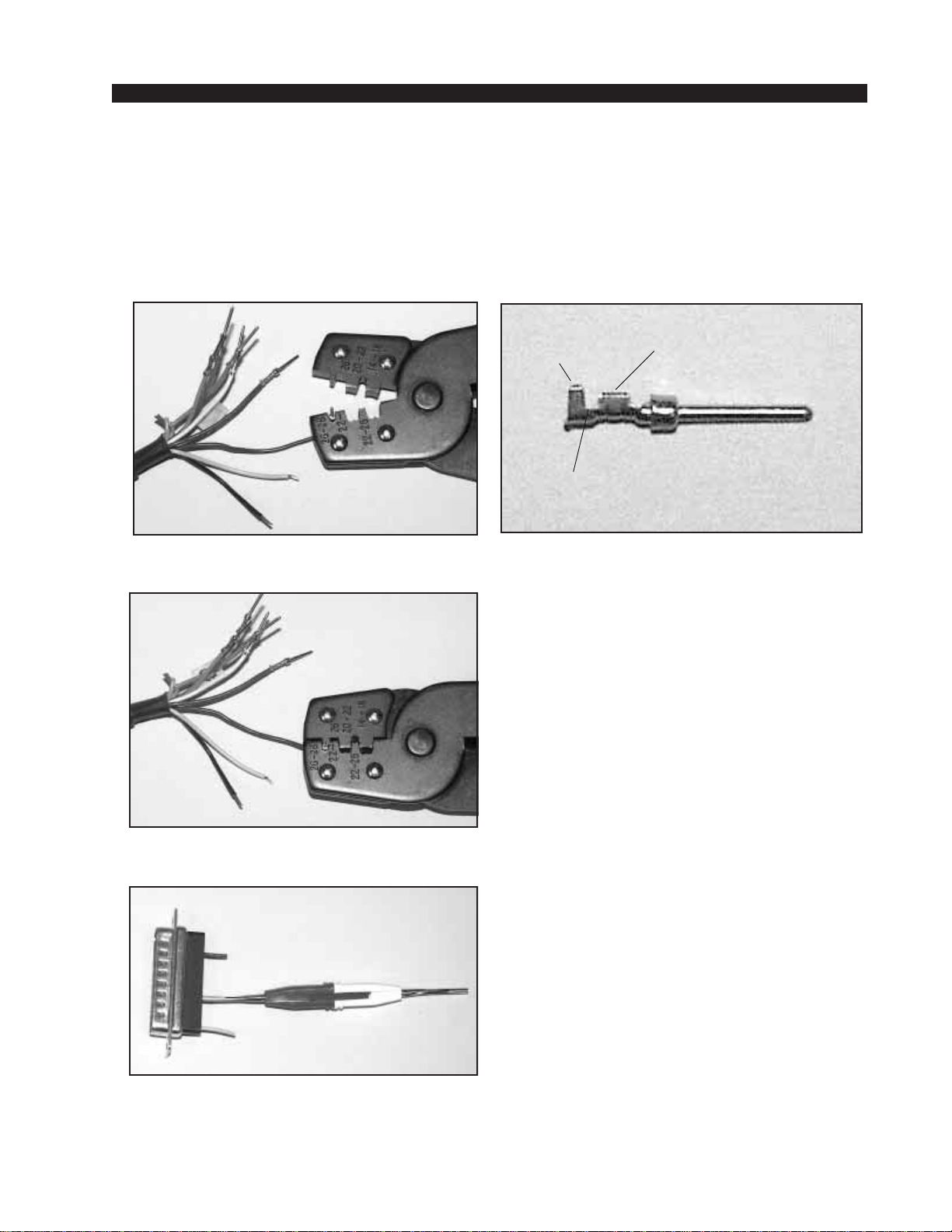
(2) The terminal conductor tabs with stripped wire
are placed in anvil 26-28.
HAND CRIMP TOOL WIRING INSTRUCTIONS
The supplied hand crimping tool (W/S#850068) is used for all I/O wiring
connections to and from the console. It is to be used with the supplied pin
(figure 1) intended for 24"-28" gauge wire.
1) Strip wire approximately 3/16" (insert in
proper wire stripper, rotate one half turn, and
pull insulation off wire).
2) Insert wire into terminal until wire
insulation is stopped by conductor tabs, and
place the conductor tabs on the anvil marked
as 26-28 (figure 2).
3) CRIMP by squeezing handles until jaws
are fully closed to secure wire in the terminal
(figure 3).
4) If there is an insertion error or if a
circuit change is needed, you'll need to use
the supplied pin extractor tool (W/S#850069)
to remove terminals, and correct your mistake
without having to sacrifice a connector. Place
extractor tip (red side) over pin terminal to be
removed (figure 4), and press it downwards
motion until tip rests upon Housing. Then
pull out the pin terminal from Housing. It
should never be necessary to discard a con-
nector due to a wiring error.
Note that metallized plastic hoods for
each connector are also supplied with the
console.
(3) Jaws fully closed; the insulation tabs have
been crimped.
(1) Pin crimp terminal
CONDUCTOR
TABS
INSULATION
TABS
INSULATION
STOPS HERE
(4) Place extractor tip over pin terminal to be
removed.

page 2 – 1
220 / March 2000
INPUT MODULE
Input Module (IND-220)
Chapter Contents
Module Overview........................................................................ 2-2
Internal Programming Options ................................................. 2-3
Insert Bypass .......................................................................................................... 2-3
Phantom Power ...................................................................................................... 2-3
Talkback.................................................................................................................. 2-3
VDT Programming Options ....................................................... 2-4
Hook-ups..................................................................................... 2-4
Microphone Inputs ................................................................... 2-4
AUDIO CONNECTIONS..................................................................................... 2-4
CONTROL CONNECTIONS .............................................................................. 2-4
Remote ON & OFF ........................................................................................... 2-5
Cough ............................................................................................................... 2-5
Talkback to Control Room................................................................................ 2-5
On Tally ............................................................................................................ 2-5
Off Tally ............................................................................................................ 2-6
Tally B ............................................................................................................... 2-6
Stereo Line Analog Inputs....................................................... 2-6
AUDIO CONNECTIONS..................................................................................... 2-6
Stereo Line Digital Inputs........................................................ 2-6
AUDIO CONNECTIONS..................................................................................... 2-6
CONTROL CONNECTIONS .............................................................................. 2-7
Remote ON & OFF ........................................................................................... 2-7
External START & STOP ................................................................................. 2-7
Ready ............................................................................................................... 2-8
Tally B ............................................................................................................... 2-8
DB Connector Pinout Drawings
Mono Mic Inputs ..................................................................................................... 2-9
Stereo Line Analog Inputs .................................................................................... 2-10
Stereo Line Digital Inputs ..................................................................................... 2-11
Mono Mic Input Signal Flow Diagram .................................... 2-12
Stereo Line Input Signal Flow Diagram ................................. 2-13
220 / Sep 2000
page 2 – 2
220 / March 2000
INPUT MODULE
Input Module (IND-220)
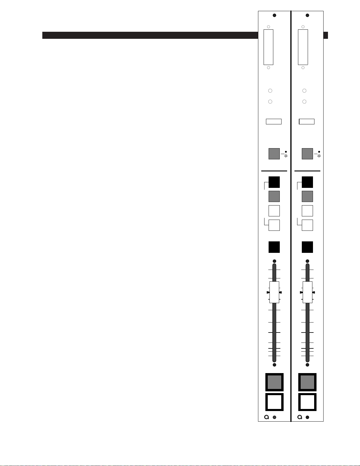
Module Overview
The IND-220 is a dual input module with double wide faceplate,
and having one main PCB card. Depending on the type of input
signals the module will handle, it will also have any combination of
twopiggybackcardsformonomicrophone(-50dBunominal),stereo
line analog, or stereo line digital inputs. Each section of the dual
module accepts two sources, A and B, switched at the top of the
module.
IND-220 modules are for microphone input signals (-50dBu
nominal) and for stereo line input signals. Each module accepts two
mono/stereo sources: A and B, switched at the top of the module.
They are available in three different versions: mono microphone
inputs, analog stereo line inputs and digital stereo line inputs.
The mono version uses an MMADC-220 piggyback card at the
input stage of the module. Phantom power is available at both input
ports; it may be selectively activated by an internal jumper (the
factory default is OFF). Recessed front panel multi-turn trimpots
(range 38dB) adjust the level of the A and B inputs independently.
Example: with a microphone input of –60dBm @150Ωat the port,
gain trim can set levels from -22dBu to +16dBu (note maximum preamp
gain is +76dB).
An insert point (+4dBu balanced) is provided: it is post-trim and
may be internally bypassed, which is the factory default setting.
TheADC(analog-to-digitalconverter)versionusesanSLADC-
220 piggyback card at the input stage of the module, and accepts
+4dBu balanced analog input signals. Recessed front panel multi-
turn trimpots adjust the left and right levels..
The SRC (sample rate converter) version uses an SRC-220
piggyback card at the input stage of the module, and accepts digital
(AES is factory default) input signals.
Output switches assign the selected source signal to any combi-
nation of the console’s four stereo outputs: PGM (program), AUD
(audition), AUX (auxiliary) and/or UTL (utility).
Level is set by a long-throw fader.
The channel ON and OFF switches are at the bottom of the
module. In addition to being controlled remotely, these can also be
programmed (via VDIP program) to perform a variety of console
control functions, including activating control room and studio
mutes, talkbacks, external tallies, and timer restart.
All audio and control input and output signals are made via a
multi-pin DB-25 connector mounted on the top of each individual
module and located underneath the hinged meterbridge.
0
5
10
15
20
30
40
50
70
60
00
0
5
10
15
20
30
40
50
70
60
00
IND IND
CUE CUE
P
G
M
A
U
D
U
T
L
A
U
X
A
S
S
I
G
N
A
S
S
I
G
N
P
G
M
A
U
D
U
T
L
A
U
X
START
A
B
A
B
O
N
O
F
F
O
N
O
F
F
MIC IN
LINE IN
DIG IN
MIC IN
LINE IN
DIG IN
I/O I/O
MIC / LINE TRIM
M1 / LT
M2 / RT
MIC / LINE TRIM
M1 / LT
M2 / RT
W# 026000AW# 026000A
MODULE TYPE MODULE TYPE
Table of contents
Other Auditronics Recording Equipment manuals


Popular Recording Equipment manuals by other brands


Behringer
Behringer POWERPLAY 16 P16-D quick start guide

Harman Kardon
Harman Kardon CDR 25 Preliminary service manual

ESD
ESD CPCI-CAN/331 Hardware installation and technical data

Monacor
Monacor DMR-1608A instruction manual

Klein Tools
Klein Tools VDV500-063 Toner-Pro instruction manual

Singular Sound
Singular Sound MIDI Maestro manual