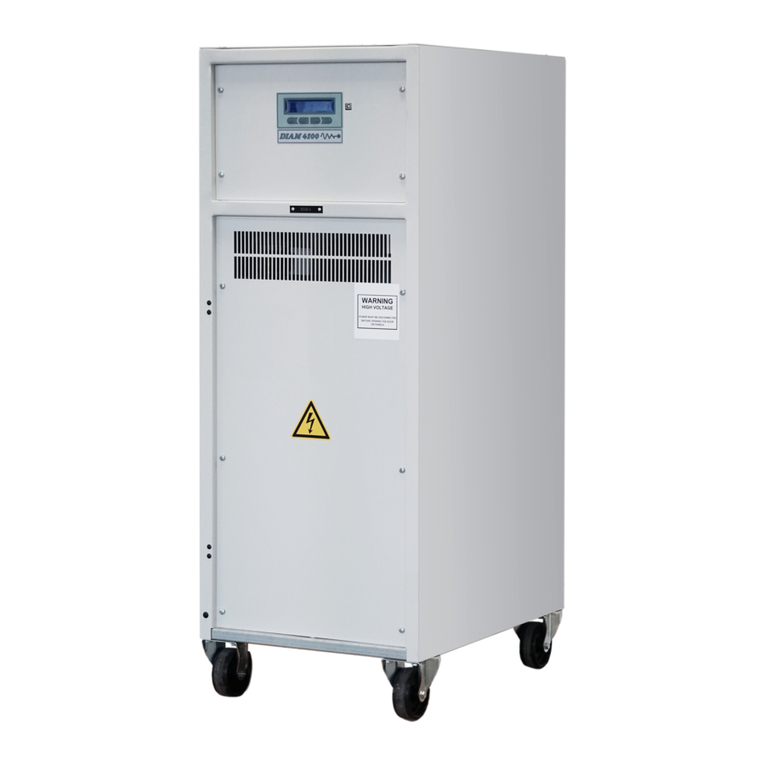
AUGIER Energy DIAM4000 Maintenance and service guide

©2004 AUGIER SA.
I-1
DIAM4000
L828/L829 and IEC Single-phase SCR-type
Constant Current Regulator
Compliance with standards:
ICAO Aerodrom design manual, part 5
IEC 61822 et 61822
CENELEC (ENV 50231)
FAA (AC 150/5345 - 10E Spec.L828/L829)
STNA (CCTP n°91068)
AENA (PPT2, rev.5, ed3(1995) and ed4(2004)
60 21032 Diam4000 (IM) rev.9
Installation & maintenance

©2004 AUGIER SA.
I-2
RECORD OF CHANGES
Rev. Pages Description From S/N By App. Date
1.0 First issue ED RG 07/01/04
1.1 V48-49 Diagrams update SC RG 15/01/04
1.2 Cover composition NA RG 19/02/04
1.3 Text corrections –IEC spare list – part number OE RG 08/03/04
1.4 Jbus table, cabinet, ECB option ED RG 18/05/04
1.5 II37-38 FAA Multiwire remote control ED RG 15/09/04
1.6 II37-38 FAA Multiwire remote control, jbus table ED RG 11/10/04
1.7 cover Standard and qualification precision’s RG RG 02/11/04
1.8 IV53 to V55 Spare lists and diagrams update 24 532 OE RG 24/11/04
1.9 II37,38,41 Connections, interlock SC RG RG 30/11/04

©2004 AUGIER SA.
I-3
WARRANTIES
Guarantee
AUGIER’s goods are guaranteed for one year from delivery date on the signed delivery note, and are
guaranteed to be free from defects in materials used, design and manufacture.
The guarantee covers repair, modification or replacement of parts or products recognised to be defective, in
the shortest possible time, at AUGIER’s cost, provided always that the goods have been properly handled and
stored prior installation, properly installed and properly operated after installation.
Unless otherwise specifically laid down in contract, the guarantee does not cover:
•Costs of consignment to factory and re-consignment of defective goods to Buyer
•If these are repaired in AUGIER’s factory;
•Travelling & sojourn expenses of AUGIER’s personnel if goods have to be repaired on site; assembly
and dismantling of any goods other than those recognised to be defective; expenses incurred for
waiting times by AUGIER’s personnel on site for reasons independent of their will;
•Unjustified travel expenses.
Guarantee shall not apply in the following cases:
•Defects in materials supplied by Buyer or from any designs imposed by them;
•Repairs or replacements due to normal wear and tear, or damages or accidents.
•Repairs or replacements due to damages or accidents resulting from negligence or lack of due care,
inadequate supervision or maintenance, or erroneous use of the equipment or software;
•Any other causes for which AUGIER shall not be held responsible, e.g. resulting from an case of Force
Majeure.
•When Buyer has replaced AUGIER’s parts with other parts.
Buyer must inform AUGIER in writing and without delay of any defects in goods, giving all necessary
information and detailed description of how equipment has been utilised, together with purchase date. Buyer
undertakes not to have repairs carried out by third parties; any repairs carried out without AUGIER’s express
prior agreement shall invalidate the guarantee.
It is expressly agreed between the two parties that Buyer cannot avail himself of the beneficial dispositions
contained in the guarantee without having first satisfied payment conditions laid down in contract
Disclaimers
This manual could contain technical or typographical errors. AUGIER reserves the right to make changes and
revise this manual from time to time without obligation to notify any person or organisation of such changes or
revision.
Values and measurements given in this manual are average values and are not binding. AUGIER disclaims any
liability for damages suffered as a result of reliance on the information given in this manual, or the use of
equipment or processes which this manual refers.
No guarantee is made that the use of the products, equipment, processes or information to which this manual
refers will not infringe any third party’s patent or rights. Information given does not release the buyer from
making their own tests.

©2004 AUGIER SA.
I-4
SAFETY
Safety precautions
This equipment is normally used or connected to circuits that may employ dangerous and lethal voltages.
Extreme caution should be exercised by operating or maintenance people when working on or with this
equipment.
See IEC 61820 & 61821 standard (CCR type IEC), or FAA AC150/5340-26 advisory circular (CCR type FAA),
concerning safety rules and precautions. While practical safety precautions have been incorporated in this
equipment, the following rules must be strictly observed :
•KEEP AWAY FROM LIVE CIRCUITS :
Operating and maintenance people must at all time observe all safety regulations. Do not change
components nor perform maintenance inside equipment with power ON or the lighting loop energised.
•RESUSCITATION :
Operating and maintenance personnel should familiarise and keep themselves trained with resuscitation
techniques found in widely published manuals about first aid instructions.
•ELECTROSTATIC DISCHARGE (ESD) :
Electronic sub-assemblies and boards should be touched only for unavoidable operation (replacement,
for example). Before to operate, maintenance people must first of all eliminate unwanted electronic
charges, discharging his own body while touching a conductive earthed object or part. Electronic boards
and components as power semiconductors must be stored and carried an conductive packing.
•DESTRUCTION :
In case of dismantling, scrapping or placing out of service, the user must follow all the required
precautions for component, materials or equipment elimination, according the local rules.
EEC DIRECTIVES
This equipment complies with the requirements of EC directives :
•89/336/EEC, 92/31/EEC and 93/68/EEC with regard of Electromagnetic
Compatibility
•73/23/EEC with regard of Low Voltage Equipment

©2004 AUGIER SA.
I-5
TABLE OF CONTENTS
RECORD OF CHANGE ……………………………………………………………………………………………… I-2
WARRANTIES …………………………………………………………………………………………………………… I-3
SAFETY ……………………………………………………………………………………………………………….….. I-4
TABLE OF CONTENTS ……………………………………………………………………………………………… I-5
IDESCRIPTION _______________________________________________________ I-9
I.1 OVERVIEW _______________________________________________________________________ I-9
I.2 MECHANICAL DESCRIPTION _______________________________________________________ I-10
I.2.1 DESCRIPTION ________________________________________________________________ I-10
I.2.2 GENERAL MECHANICAL FEATURES _____________________________________________ I-10
I.2.3 STORAGE CONDITIONS________________________________________________________ I-11
I.2.4 DIMENSIONS_________________________________________________________________ I-11
I.3 ELECTRICAL DESCRIPTION________________________________________________________ I-12
I.3.1 BLOCK DIAGRAMS ____________________________________________________________ I-12
I.3.1.1 Overview: __________________________________________________________________ I-12
I.3.1.2 Electronic: __________________________________________________________________ I-12
I.3.2 GENERAL CIRCUIT DIAGRAMS__________________________________________________ I-12
I.3.3 GENERAL ELECTRICAL FEATURES______________________________________________ I-13
I.4 INSTRUCTIONS FOR USE __________________________________________________________ I-14
I.4.1 USER INTERFACE_____________________________________________________________ I-14
I.4.2 CONTROL ___________________________________________________________________ I-16
I.4.3 LOCAL INFORMATION FEEDBACK _______________________________________________ I-16
I.4.4 REMOTE INFORMATION FEEDBACK _____________________________________________ I-18
I.5 OPERATION _____________________________________________________________________ I-19
I.5.1 CONFIGURATION _____________________________________________________________ I-20
I.5.2 SETTING ____________________________________________________________________ I-20
I.5.2.1 Current range: _______________________________________________________________ I-20
I.5.3 PROTECTIONS _______________________________________________________________ I-20
I.5.3.1 LV power monitoring: _________________________________________________________ I-20
I.5.3.2 “Open circuit”: _______________________________________________________________ I-20
I.5.3.3 “Overcurrent”: _______________________________________________________________ I-21
I.5.3.4 Cancelling “Open circuit” and “Overcurrent” faults:___________________________________ I-21
I.5.4 AUTOMATIC OPERATION: ______________________________________________________ I-21
I.6 SUB-ASSEMBLIES________________________________________________________________ I-22
I.6.1 LOAD PLATE _________________________________________________________________ I-22
I.6.1.1 Adaptation to load: ___________________________________________________________ I-22
I.6.1.2 Computation of the output voltage and output power: ________________________________ I-23
I.6.2 CUT OUT AND EARTHING PLATE (OPTION) _______________________________________ I-24
I.6.2.1 Normal position : _____________________________________________________________ I-24
I.6.2.2 Safety position: ______________________________________________________________ I-24
I.6.2.3 Load measurements:__________________________________________________________ I-24

©2004 AUGIER SA.
I-6
I.7 ACCESSORIES___________________________________________________________________ I-25
I.7.1 “ALIZE4000” SOFTWARE _______________________________________________________ I-25
I.7.2 “RDTS4000” SOFTWARE _______________________________________________________ I-25
I.8 OPTIONS________________________________________________________________________ I-26
I.8.1 EARTH FAULT DETECTOR (EFD) ________________________________________________ I-26
I.8.2 OPTIONAL ISOLATING DEVICES_________________________________________________ I-26
I.8.2.1 Cut-out and earthing plate : See 1.6.2 ____________________________________________ I-26
I.8.2.2 FAA cut-out plug:_____________________________________________________________ I-26
I.8.3 OUTPUT LIGHTNING ARRESTORS_______________________________________________ I-26
I.8.4 INPUT LIGHTNING ARRESTORS_________________________________________________ I-26
I.8.5 CASTERS____________________________________________________________________ I-26
I.8.6 BURNT LAMPS DETECTION: ____________________________________________________ I-27
I.8.7 OUTPUT POWER DROP DETECTION: ____________________________________________ I-27
I.8.8 TIME METERS: _______________________________________________________________ I-27
I.8.9 4-20MA LOOP CURRENT : ______________________________________________________ I-28
I.8.9.1 4-20mA current loop for output current and power measurements : _____________________ I-28
I.8.9.2 4-20mA loop current (ground insulation):__________________________________________ I-28
I.8.10 BUZZER _____________________________________________________________________ I-29
I.8.11 WIG WAG ____________________________________________________________________ I-29
I.8.12 OTHER OPTIONS _____________________________________________________________ I-29
II INSTALLATION _____________________________________________________ II-30
II.1 PREPARATION___________________________________________________________________II-30
II.1.1 EQUIPMENT RECEPTION ______________________________________________________II-30
II.1.1.1 Equipment delivered:________________________________________________________II-30
II.1.1.2 Checking the equipment:_____________________________________________________II-30
II.1.2 DEVICE LOCATION____________________________________________________________II-30
II.1.3 CHECKING THE INSTALLATION _________________________________________________II-31
II.1.3.1 Single phase power supply:___________________________________________________II-31
II.1.3.2 LV Protection: _____________________________________________________________II-31
II.1.3.3 Lighting loop: ______________________________________________________________II-31
II.1.3.4 Management by remote control: _______________________________________________II-31
II.2 CONNECTIONS___________________________________________________________________II-32
II.2.1 ELECTRICAL _________________________________________________________________II-32
II.2.1.1 LV supply: ________________________________________________________________II-32
II.2.1.2 Earthing __________________________________________________________________II-32
The Main Earth circuit must be connected to the earthing stud situated in the lower part of the frame at left
(external or internal connection, at rear) __________________________________________________II-32
II.2.1.3 Lighting loop: ______________________________________________________________II-33
II.2.1.4 Remote control connections __________________________________________________II-34
II.2.1.4.1 CONFIGURATION OF REMOTE CONTROL TYPE________________________________II-34
II.2.1.4.2 FAA Multiwire remote control (FAA type CCRs only, with 20 to 60Vdc inputs))___________II-35
II.2.1.4.3 IEC Multiwire remote control (IEC type CCRs only): _______________________________II-37
II.2.1.4.4 Operating modes for multiwire (FAA & IEC) remote control :_________________________II-39

©2004 AUGIER SA.
I-7
II.2.1.5 Serial Link:________________________________________________________________II-40
II.2.1.6 Circuit selector: ____________________________________________________________II-41
II.3 ADJUSTING THE CCR _____________________________________________________________II-43
II.3.1 ADAPTATION TO LOAD ________________________________________________________II-43
II.3.1.1 Maximum power levels by power settings: _______________________________________II-43
II.3.2 PARAMETER MODIFICATION ___________________________________________________II-43
II.3.2.1 Preferred configuration values: ________________________________________________II-43
II.3.2.2 Brightness values: __________________________________________________________II-44
II.3.2.3 Value of “Open Circuit” protection level: _________________________________________II-44
II.3.2.4 Value of “Overcurrent” protection levels:_________________________________________II-44
III COMMISSIONING_________________________________________________ III-45
III.1 PROCEDURE ___________________________________________________________________ III-45
III.2 TESTS _________________________________________________________________________ III-46
III.2.1 SHORT-CIRCUIT TESTS_______________________________________________________ III-46
III.2.2 OVERLOAD TESTS ___________________________________________________________ III-46
III.2.3 OPEN-CIRCUIT TEST _________________________________________________________ III-46
IV MAINTENANCE___________________________________________________ IV-47
IV.1 FORMALISATION ________________________________________________________________ IV-47
IV.2 PREVENTIVE ___________________________________________________________________ IV-47
IV.2.1 FIRST MONTHS______________________________________________________________ IV-47
IV.2.2 ANNUAL PROCEDURE ________________________________________________________ IV-47
IV.2.3 EVERY THREE YEARS ________________________________________________________ IV-47
IV.3 CORRECTIVE ___________________________________________________________________ IV-48
IV.3.1 FAULT DIAGNOSIS ___________________________________________________________ IV-48
IV.3.1.1 LV power fault:____________________________________________________________ IV-48
IV.3.1.2 “Open Circuit” fault: ________________________________________________________ IV-49
IV.3.1.3 “Overcurrent” fault:_________________________________________________________ IV-50
IV.3.2 OTHER FAULTS______________________________________________________________ IV-51
IV.4 VERIFICATION PROCEDURES _____________________________________________________ IV-52
IV.4.1 THYRISTORS________________________________________________________________ IV-52
IV.5 SPARE PARTS LIST FOR FAA TYPE CCR ___________________________________________ IV-52
IV.6 SPARE PARTS LIST FOR IEC TYPE CCR ____________________________________________ IV-55
VAPPENDIX A: DIAGRAMS ____________________________________________V-56
VI APPENDIX B: JBUS TABLE_________________________________________ VI-58
VII APPENDIX C: PART NUMBER IDENTIFICATION________________________VII-66

©2004 AUGIER SA.
I-8
ABBREVIATIONS
Abbreviation Definition
AAmpere
AC Alternating Current
B Brightness
CCR Constant Current Regulator
DC Direct Current
EFD Earth Fault Detector
HV High Voltage
IT Injection Transformer
LFD Lamp Fault Detector
LV Low Voltage
OO Out of order
VVolt
VA Volt-Ampere

©2004 AUGIER SA.
I-9
IDESCRIPTION
I.1 OVERVIEW
DIAM4000 series CCRs are low costs fully static devices controlled by two thyristors (anti-parallel mounting
type dimmer). They are designed to maintain a constant, pre-displayed and adjustable output current
independently of the load and power supply fluctuations.
These devices are specifically designed for airfield lighting on runways, taxiways, aprons. They meet both
national and international standards.
In order to do this, they use an adapted triggering and regulation mechanism that is not affected by external
interference and does not emit measurable interference in the Aviation Band between 100 and 400 MHz.
This type of regulator uses natural air-cooling. The output current remains constant with an accuracy of 1%
for mains voltage fluctuations of –5/+10% (+/-10% for IEC type). At the rated load and the rated or higher
voltage, accuracy of regulation is maintained for all load between 0 and 100%, and for up to 30% of
transformers with open secondary. The output power of the regulator can be adjusted to the load by means of
transformers taps, by steps of 12.5%.
Here are some of its advantages:
•Flexibility of use:
The alphanumeric display and menu type keyboard allow the CCR to be configured without connection
with a computer.
Regulation is fully digital which enables parameters to be simply modified for a particular load.
Emergency and warning messages are clearly displayed.
•Simplicity:
CCR type regulators have a very simplified architecture both for the electronic control unit and the LV
and HV power parts.
•Adaptability and safety:
An optional Cut-out and Earthing plate, using two pluggable jumpers can be used to disconnect the
CCR from the loop, to earth or short-circuit the loop without disconnecting the load at any time.
•Construction:
It has been optimised to keep the number and variety of spare parts to a minimum. The device is made
up of modular sub-assemblies.
•Standards:
ICAO: Airport design manual, part 5
STNA: CCTP 91068 rev.93
CENELEC: prENV 50231
FAA: AC150/5345-10E, L828 or L829
AENA: PPT NTA2-rev.5 (1995) & ed.4 (2004)
IEC: 61822 (CCRs), 61821 (Maintenance)

©2004 AUGIER SA.
I-10
I.2 MECHANICAL
DESCRIPTION
I.2.1 DESCRIPTION
Each CCR is housed in a cabinet fitted with lifting rings. The frame has three distinct parts: an “electronic”
control part, a “low voltage” compartment and a “high voltage” compartment.
•The Electronic unit of the CCR consists of a main electronic circuit board fitted to the upper panel of the
cabinet.
All the basic functions of the regulator are included in the electronic compartment and are accessible from
the front and the top of the CCR.
•The Low voltage unit contains all the components connected to the power supply with, for example, the
thyristors and associated driver boards, the master switch, the LV fuses and connection terminals. It is
located in the upper part of the CCR.
•The High voltage unit, situated at the back of the CCR, contains all the components connected to the
output loop such as the power transformer, the lightning arrestors, the CI-MALT (optional) and the HV part
of the insulation fault detection unit. The load regulating plate and the load loop connections are accessible
from the front of the device.
All these components are easily accessible from the front, the top or the back of the cabinet.
I.2.2 GENERAL MECHANICAL FEATURES
Regulators are contained in the same cabinet for all powers and input voltage. A taller one (+ 20cm) is available
when inside additional equipment is requested by customer, as ECB (*) option. Both cabinets are provided with
hoisting eye rings, with or without casters, and can be located cuddled up to each other.
Standard cabinet : 500mm Wide x 700mm Deep x 1380mm High
Big cabinet : 500mm Wide x 700mm Deep x 1580mm High
•Protection Index for the Casing: IP 21. (Contact us for other Protection Indices)
•Distances inter-axes (if casters option) : 355 x 610 mm
•Usage: Ambient temperature between -40°C and +55°C (FAA type) or –20°C to +55°C (IEC type),
with maximum relative humidity of 95%. Natural air cooling.
(*) ECB : Loop Communication Equipment, type STB or SCB (Please ask for more informations)

©2004 AUGIER SA.
I-11
I.2.3 STORAGE CONDITIONS
The components are designed to be stored in a dry, airy location, sheltered from rain, water discharges
and chemical agents. We must be consulted if the components are to be stored outside, or in an ambient
temperature out of the range -40°C/+55°C.
I.2.4 DIMENSIONS
A(mm) B(mm) C(mm)
1 to 30 kVA 1380 500 700
With ECB (*) 1580 500 700
Load 2,5kVA 4kVA 5kVA 7,5kVA 10kVA 15kVA 20kVA 25kVA 30kVA
Weight 135 kg 155kg 155kg 170kg 175kg 220kg 280kg 295kg 330kg
(*) ECB : Loop Communication Equipment
B
A
C

©2004 AUGIER SA.
I-12
I.3 ELECTRICAL
DESCRIPTION
I.3.1 BLOCK DIAGRAMS
LSee paragraph I.5 for the device operating description
I.3.1.1 Overview:
I.3.1.2 Electronic:
I.3.2 GENERAL CIRCUIT DIAGRAMS
LSee Appendix A
Measurements
Current,
Voltage
RS232/RS485
Power supply
Settings
DIAM Motherboard
DIAM
Daughter Board
Keyboard
Display
Thyristor control
board
Measurement Board
Input
circuits Main
Contactor Thyristors
dimmer LV/HV
Transformer Output
circuits
Control &
Monitoring Measuring
Board
Interfaces
EFD Data

©2004 AUGIER SA.
I-13
I.3.3 GENERAL ELECTRICAL FEATURES
•Power supply voltage:
Single phase; two series :
FAA type : 208Vac, 220Vac, 240Vac, 277Vac, 400Vac, 480Vac –5/+10%, 50 or 60 Hz ±5%.
IEC type : 220Vac, 230Vac, 240Vac, 380Vac, 400Vac, 415Vac +10/-10%, 50 or 60Hz ±5%
•Maximum rated current: 6.6 A (other values available).
•Number of Brightness Levels: maximum 8, adjustable.
•Heating Brightness (“Black current”):
The CCR can produce “heating” level brightness at low current (1.5A prefered), which is used to remove
condensation from the interior of the lamp lenses without lighting up their bulb. The symbol for local
setting is ‘B0’.
•Remote Control: By voltage from 20V to 60V DC positive or negative, or dry contact, or 120Vac,
and/or serial network.
•Remote indication:
FAA type : Relays, 120VAC , 2A max, 10µA min., and/or serial network
IEC type : Static dry contacts relays, 48Vdc, 0.1A max, and/or serial network
•Output power: 1, 2.5, 4, 5, 7.5, 10, 15, 20, 25, 30 kVA
•Power factor:
FAA type : > 90% (2.5 to 10kW CCRs) or > 95% (15 to 30kW CCRs), at voltage and rated resistive load
IEC type : > 90% at nominal voltage and rated resistive load
•Efficiency : > 90% at nominal voltage and rated resistive load.
•Output Current Regulation:
Better than ±1% under the following conditions: Power supply voltage: ±10% (IEC) or –5/+10% (FAA) -
Frequency: ±5% - Load: from 0 to 100%
•Load adaptation:
The output transformer is equipped with an epoxy plate including adjustment taps in order to adapt the
rated output voltage of the CCR to the present load. Two brass straps allow load adaptation with steps
of 12.5%, between 12.5% and 100% (8 possibilities).
•Protection:
The electronic circuitry is protected against fluctuations by the use of a Hall effect sensor for measuring
current, and fibre optics for thyristors control. Electronic board manages all overcurrent, open circuit or
mains under/over voltage.
•LV Protection:
A set of high-power fuses (or optional circuit breaker), a set of fuses for the power supply to the
auxiliaries, and “glass” fuses on the circuit boards provide LV protection.
•Lightning arrestors :
These regulators can be optionally provided with input and output lightning arrestors.

©2004 AUGIER SA.
I-14
I.4 INSTRUCTIONS FOR USE
I.4.1 USER INTERFACE
Operating mode:
Stop mode :
Preferred information displayed: they can be changed by a long press on the “STOP” key, meanwhile the CCR
is in Stop mode. The choice can be :
•Output current Io – Brightness state Bx (as seen in examples below and above)
•Output current Io – Output power Po
•Output current Io – Output voltage Uo
Local mode :
Access is given to B+ and B-, in order to increase / decrease the brightness.
Remote control mode :
“Auto” is highlighted, in order to indicate the current state.
Brightness selection in local mode:
:Decrease brightness in local mode Increase brightness in local mode
Io:0.00A STOP
stop local auto menu
Io:6.60A <B5>
stop B- B+ menu
Io:5.20A <B4>
stop local auto menu
Io:6.60A <B5>
stop B- B+ menu

©2004 AUGIER SA.
I-15
Menus:
Access to menu
To navigate in the menus
Alarms and Warnings:
Alarm (the CCR failed to supply the load); for example, the CCR is stopped by a loop open circuit :
Cancel fault(s)
Warning (the CCR doesn’t stop; warning is only indicative); for example the earth insulation fault level 1 is
detected :
RS232 serial link:
A 9-pin SubD female socket is located in front of the CCR, in order to connect a lap-top computer
Rx: indicator Data reception on RS232 or RS485 connection
Tx: indicator Data transmission on RS232 or RS485 connection
Rx Tx
Alphanumeric display:
VFD display (16 x 140 pts) : upper text in Blue (information datas), lower text (key definition) in Purple.
Screen saver : The brightness decreases automatically or turn off after one hour if the keyboard is not used.
Turns on again instantly when a key is pressed. (Function user-definable)
Io:0.00A STOP
stop local auto menu
Monitoring
esc OK
ALARM: I<<Open Cir.
reset
Warning: :EFD Level1
stop local auto menu
Io:5.20A <B4>
stop local auto menu

©2004 AUGIER SA.
I-16
I.4.2 CONTROL
The device is controlled by mean of a 4 buttons keypad which allows to change the operating mode: “Stop” –
Manual or “Local” mode – Remote or “Auto” control mode.
•Stop mode:
In that mode, “Stop” is highlighted. The CCR stops, whatever the current brightness orders (remote control or
local selection).
Menus can then be accessed.
•Local mode:
In that mode appears brightness controls : The brightness is chosen by pressing buttons B- and B+ (from B0 to
B7 maximum, according to the number of brightness levels configured).
•Remote control mode:
In that mode, “Auto” is highlighted. Operation of the CCR is governed by remote control inputs on the CCR’s
motherboard. If remote control commands overlap, priority is given to the first choice of brightness. The remote
control is either of the multiwire type (20 to 60 DC positive or negative, or 120Vac), or the dry-contact type with
internal power supply, and/or given by the mean of a serial network.
LSee paragraph II.3 for configuring the remote control type.
LSee paragraph II.3 for adjusting brightness values and protection levels.
I.4.3 LOCAL INFORMATION FEEDBACK
Alphanumeric display:
•The display shows the RMS current flowing in the loop and the selected brightness (preferably).
In the “Monitoring” menu, the following information are shown:
•Uo: RMS output voltage in Vrms
•Po: RMS output power in KVA
•Ui: Mains power supply voltage in Vrms
•If option “EFD” exists: Insulation resistance of the loop with respect to earth in KOhms
•Load plate tap value from 0 to 100% (0 to 8/8 by increments of 1/8)
•If option “LFD” exists: Number of burnt lamps, and VA drop if FAA type
•The operating time (powered on and for each brightness) in Hours
Io:0.00A STOP
stop local auto menu
Io:6.60A <B5>
stop B- B+ menu
Io:0.00A <-->
stop local auto menu

©2004 AUGIER SA.
I-17
Warning:
WARNING is an indicative message, which does not change regulation and supply function in connection with
the load. (Except for mains warning)
If any warning have been detected, the following message(s) can be shown on the display:
•If option “EFD” exists:
“No HV (500V) EFD” (no injection voltage : measurement of earth leakage cannot be done)
“R Level EFD1” (A leakage has been detected, with a resistance value lower than the level 1).
“R Level EFD2” (A leakage has been detected, with a resistance value lower than the level 2).
•If option “Burnt lamps” exists:
“Level 1 Burnt lamps” (The current number of burnt lamps is greater than level 1)
“Level 2 Burnt lamps” (The current number of burnt lamps is greater than level 2)
“Power drop” (if FAA selected : the load was cut more than 10%, in VA)
•Mains power supply outside limits (Input voltage lower or greater than +/-10%)
•Regulation outside limits (as “error regulation” programmed values)
Fault:
ALARM represents a major fault of the CCR or due to an external event, which have stopped the CCR (in order
to protect itself or the lighting loop).
In case of fault or damage, the display shows that the CCR stopped and one or more faults have been detected.
The following message(s) are shown on the display:
•Overcurrent Level 1 (after a trial to restart, the CCR cannot contain the output current which had reach
the 1stlevel as programmed)
•Overcurrent Level 2 (ditto, for 2nd level)
•Overcurrent Level 3 (ditto, for 3rd level)
•Peak Overcurrent (ditto, for a 4th level, not configurable)
•Open circuit (the CCR detected an output current lower and during a greater time than the programmed
parameters)
In order to re-start (after having fixed the fault), cancel the ALARM pressing the RESET key.

©2004 AUGIER SA.
I-18
I.4.4 REMOTE INFORMATION FEEDBACK
Dry contacts:
Information returned:
•Selected brightness
•Operating mode: Local/Remote control
•“Open Circuit” fault
•“Overcurrent” fault
•If option “EFD” appears: EFD Level 1 and 2 warnings
•If option “Burnt lamps” appears: Burnt lamps level 1 and 2 warnings
•If option “Burnt lamps” and FAA type: Power drop
LSee the “Remote control terminal block” connection table in the appendix.
Insulated JBUS RS232 or RS485 link:
A JBUS table is accessible via an insulated JBUS RS485 link (1 RS485 option) or through the front 9pins SubD
socket.
The values in the table are used to control and monitor the device remotely.
LSee the JBUS table in the appendix for more details.

©2004 AUGIER SA.
I-19
I.5 OPERATION
LThe “Parameter Access” function must be activated before changing parameters, in order to
avoid unwanted changes.
Pressing the menu touch, the display shows:
then scroll through the top-level menu items using the and keys. When the “Options” item is shown
like:
press OK to go into the “Options” menu, then scroll through the items until the “Param. access: NO” item is
displayed:
Press modif in order to modify the parameter. When the "NO" displayed blinks, it is possible to change the
parameter : press <or >to in order to change “NO”to“YES”:
Save the modification by pressing OK .
Press esc twice to go back to the initial state.
ALL PARAMETERS ARE MODIFIED USING THE SAME PROCEDURE.
Monitoring
esc OK
Options
esc OK
Param. access: No
esc modif
Param. access: Yes
esc OK

©2004 AUGIER SA.
I-20
I.5.1 CONFIGURATION
The “Configuration” menu is used to define the basic parameters of the CCR (for example when replacing the
main board):
•Rated mains voltage in Vrms: 208-220-230-240-277-380-400-415-480
•Rated power in KVA:1-2.5-4-5-7.5-10-15-20-25-30
•Number of brightness (Including B0): from 1 to 8
•Mains frequency in Hz: 50 or 60
•FAA or IEC type
I.5.2 SETTING
The “Setting” menu is used to assign values of current to brightness levels B0 to B7.
•Minimum value = 1Arms
•Maximum value = 6.8Arms
I.5.2.1 Current range:
The “Regulation Error” warning is triggered if the measured current is outside the ranges defined for each
setting B0 to B7.
Each range is automatically calculated when a setting is changed (as described below) in the following way:
•Minimum value = Setting – 3%
•Maximum value = Setting +3%
Nevertheless it is possible to set two limits of the current range manually using the “Current range” menu.
I.5.3 PROTECTIONS
I.5.3.1 LV power monitoring:
Mains voltage Duration CCR status
Ui < 75% of rated voltage 0s CCR stops (Power supply Warning)
Ui > 130% of rated voltage 0s CCR stops (Power supply warning)
Ui < 85% of rated voltage 60s CCR stops (Power supply warning)
Ui > 120% of rated voltage 60s CCR stops (Power supply warning)
90% < Ui < 110% of rated voltage 0s CCR automatically restarts
I.5.3.2 “Open circuit”:
Open Circuit Protection is activated if the output current goes below a defined value (I level OC)fora
defined period (Duration OC). The CCR stops instantly, and the display shows the message “Open Circuit”.
Setting IlevelOCand Duration OC:
Go into the menu “Alarms and Warnings” then “Open Circuit”.
Table of contents
Other AUGIER Energy Controllers manuals
Popular Controllers manuals by other brands
Permobil
Permobil R-net user manual
ATWELL
ATWELL VG OSG Operation and installation manual
ANDO Technik
ANDO Technik Galcon 800248 Installation and operating manual

3M
3M Versaflo V-500E User instructions
Parker
Parker Sporlan SUBCOOL-O-MATIC Installation and servicing instructions
Full Gauge
Full Gauge TC-900EL Log manual
STORK TRONIC
STORK TRONIC ST552 Glass manual
PROSPERITY GROUP
PROSPERITY GROUP TRAXON e:cue 3 mx INFORMATION FOR USE
RoboteQ
RoboteQ Dual Channel Digital Motor Controller AX500 user manual
ProtACT
ProtACT PRY Series manual
Siemens
Siemens GGA 1E Series Mounting instructions
Maxcess
Maxcess MAGPOWR Spyder-Plus-S1 instruction manual

