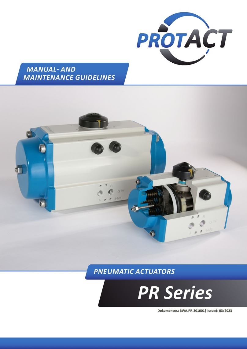
ProtACT PRY Series User manual

Series PRY
PNEUMATIC ACTUATORS
Documentnr.: BWA.PRY.200116| Issue: Jan. 2020
MANUAL AND
MAINTENANCE GUIDELINES

MANUAL & MAINTENANCE GUIDELINES
PNEUMATIC ACTUATORS SERIES PRY
BWA.PRY.200116
January 2020
2

MANUAL & MAINTENANCE GUIDELINES
PNEUMATIC ACTUATORS SERIES PRY
BWA.PRY.200116
January 2020
3
Content:
Chapter1: Preparaon
1.1 Marking of safety instrucons Page 4
1.2 Safety fundamentals Page 4
1.3 Instrucons for storage Page 4
Chapter 2: Preliminary
2.1 Design descripon Page 5
2.2 Intended use Page 6
2.3 Technial informaon Page 6
2.4 Typecode Page 7
Chapter3: Installaon
3.1 Remarks Page 8
3.2 Installaon instrucons Page 9
3.3 Seng the end posions Page 10
3.4 Assembly to a valve Page 11
3.5 Tightening torques for screw connecon Page 11
Chapter 4: Maintanance
4.1 General Page12
4.2 Safety instrucons Page12
4.3 Disassembly and maintenance of the modules Page13
4.3.1 Spring module Page13
4.3.2 Pneumac module Page14
4.3.3 Center module Page14
4.3.4 Manual hydraulic module Page15
4.3.5 Mechanical manual module Page16
4.4 Field reversion Page17
4.4.1 Changing the direcon of spring acon Page17
4.4.2 Conversion from double-acng to single-acng Page18
4.4.3 Conversion from single-acng to double-acng Page18
4.5 Components Page19
Copyright
This document is protected by copyright. We reserve all rights to this manual before proceeding, even the reproduc-
on and / or duplicaon in any thinkable form, e.g. photocopying, prinng, on data medium or in translated form.
Reproducon of this manual only with wrien permission of ProtACT GmbH. The technical state at the me of deliv-
ery of device and manual is decisive, if no other informaon is given. We reserve the right to make technical modi-
caons without specic noce. Earlier instrucons then become invalid.

MANUAL & MAINTENANCE GUIDELINES
PNEUMATIC ACTUATORS SERIES PRY
BWA.PRY.200116
January 2020
4
Chapter1:Preparaon
Content:
• Marking of safety instrucons
• Safety fundamentals
• Instrucons for storage
1.1Markingofsafetyinstrucons
1.2 Safety fundamentals
The installaon, assembly, commissioning, maintenance and any other work on pneumac actuators must be
performed by qualied personnel.
This manual is part of the device and must be available for the operang personnel at all mes. This manual must
be read and understood before operaon.
The device may only be operated in perfect condion. No safety devices are removed or deacvated. A rebuilding
or modicaon of the device is strictly prohibited.
1.3 Transport, storage and packaging
The devices must be carefully handled, transported and stored.
The devices should be transported to the end desnaon in their original packaging and unpacked immediately
before installaon.
The actuators are to be stored in a clean, dry storage, which is neither exposed to excessive vibraon nor to rapid
temperature changes.
Prevent ingress of dirt or moisture into the actuator. Close or ghten both air connecons.
Proper disposal of packaging is the customer´s responsibility.
Thissymbolindicatessafetyinstruconswhichcancausepersonalinjuryifnotrespected.
This symbol indicates an important note
Rotaryactuatorsmustbeisolatedbothpneumacallyandelectricallybeforeanyintervenon.
Failuretofollowthesafetybasicscanvoidthewarrantyclaims.
Installaon,operaonandmaintenanceoftheproductsarestrictlysubjecttothelocalsafetyand
accidentprevenonregulaons!
Failuretocomplymayvoidthewarrantyclaims.

MANUAL & MAINTENANCE GUIDELINES
PNEUMATIC ACTUATORS SERIES PRY
BWA.PRY.200116
January 2020
5
Chapter 2: Preliminary
Content:
• Design descripon
• Intended use
• Technical informaon
• Type code
2.1Designdescripon
Pneumac actuators of the PRY series are designed for the automaon of rotary valves with a 90° rotaon angle.
They have a modular structure and, depending on the applicaon, consist of one or two pneumac modules, a
center module, a spring module and an oponal module for manual actuaon. In the single-acng version, the spring
module ensures closing or opening in the event of a control media failure (spring-closing or spring-opening).
Two characterisc torque proles are available for generang a drive torque that is adapted to the valve torque.
These are created using either a symmetrical or a canted yoke.
The PRY actuator series oers a torque range of 1000 – 250.000 Nm (double-acng) and 300 – 150.000 Nm (single-
acng). The standard version of the actuators provides valve mounng interfaces according to ISO 5211 and an
accessory interface according to VDI/VDE 3845.
The maximum operang pressure of the pneumac Scotch-Yoke actuators of the PRY series is between 3 and 10 bar
depending on size and conguraon. The maximum operang pressure is specied on the typelabel of the respecve
actuator.

MANUAL & MAINTENANCE GUIDELINES
PNEUMATIC ACTUATORS SERIES PRY
BWA.PRY.200116
January 2020
6
2.3TechnicalInformaon
Construconprinciple: Pneumac heavy-duty rotary actuator in Scotch-Yoke design; double and single
acng version
Materials See secon 4.5
Temperature range
Standard
Low temperature version
High temperature version
-20°C to +80°C
-40°C to +80°C
-15°C to +150°C
Control pressure 3 … 10 bar (depending on the actuator version, check typelabel!)
Pressure media
dry, ltered air or inert gases in respect of remaining oil-,
dust and water-content according to DIN ISO 8573-1 / class 4,
maximum parcle diameter 30µm,
dew point minimum 10°C below ambient temperature
Nominalrotaonangle 90°, adjustable in both end posions +/-6°
Torque range double-acng: up to 250.000Nm
single-acng: up to 150.000Nm
Standards
Interface actuator/control-unit: VDI/VDE 3845 resp. NAMUR
Interface actuator/control media supply: G- or NPT-Thread
Interface actuator/valve: ISO 5211
2.2 Intended use
Actuators of the PYR series are primarily used for the automaon of quarter-turn valves such as ball valves, buery
valves or plug valves, but can also be used for other applicaons. Contact our qualied personnel where required.
The specied operang and liming values for temperature, pressure, control medium, etc. must be observed.In
operaon of valves high kinec energies may arise, which are transmied to the actuator. Make sure that the drive
is protected from damage by complying with the minimum travel mes safely. Control speed can be reduced by the
use of throle valves, which can be purchased from our sales department.
For valve types with high ywheel mass and low torque requirements the operang condions of the actuator must
be coordinated with us in advance.
The actuator may only be used:
• in perfect condion
• as spulated
• safety- and danger-conscious in consideraon of the operang instrucons
• if all safety devices are in place and funconing
Anyusenotpre-approvedbythemanufacturerisconsideredimproper!

MANUAL & MAINTENANCE GUIDELINES
PNEUMATIC ACTUATORS SERIES PRY
BWA.PRY.200116
January 2020
7
PRY .C1 .50 1 S .04 .1625 S 55 .P R S .00
Type
Body size
Cylinder size
Quantycylinders(1or2)
Funcon
D: double-acng
S: single-acng
Spring set
ISOvalveinterface
14: F14 1625: F16 + F25
16: F16 2530: F25 + F30
25: F25 3035: F30 + F35
30: F30 4048: F40 + F48
35: F35 4860: F48 + F60
40: F40
48: F48
60: F60
Stemconnecon
S: Square acc. to ISO 5211 or DIN 3337
D: Double-D
K: Key connecon
Stemconnecondimension
Dimension in mm (not applicable for key connecon)
Mounngdirecon
P: Parallel to pipe
T: Transversal to pipe
Springrotaonsense
R: Clockwise CW (Normally closed)
L: Counterclockwise CCW (Normally open)
Temperatureversion
S: Standard (-20°…+80°C)
H: High temperature version (-15°…+150°C)
T: Low temperature version (-40° … +80°C)
Manualoperaon
00: without
01: Screw manual
02: Gear manual
03: Hydraulic manual
2.4 Typecode

MANUAL & MAINTENANCE GUIDELINES
PNEUMATIC ACTUATORS SERIES PRY
BWA.PRY.200116
January 2020
8
Chapter3:Installaon
Content:
• Remarks
• Installaon instrucons
• Seng the end posions
• Assembly to valve
• Tightening torques for screw connecons
3.1 Remarks
1. Onlylithedriveusingsuitableliingstraps.Theholesprovidedfortheeyeboltsareonlyfor
liingtheactuatorandnotforliingtheenreassemblyincl.valve.
2. Toachievethedesiredservicelifeoftheactuator,onlytherecommended,lteredcontrolmedia
may be used
3. Theactuatormustnotbeinstalledinpotenallyexplosiveareasthatarenotcompablewith
thespeciedgasgroupsandtemperatureclasses.
4. Whenusingaseparatemanualemergencygearbox,itmustbeensuredthatthegearboxoersa
rotaonanglethatcorrespondsatleasttothatoftheactuator.
5. Theactuatorscanbeinstalledinanyposion.However,caremustbetakentoensurethatsome
accessories,suchaslterregulangunits,reservoirsforhydraulicoverrideunits,etc.,whose
properfunconingdependsongravity,arerealignedappropriately.
6. Thespringcontainerandtheendcoverofthespringmoduleprotectthespring.Duetothe
preloadforceofthespring,itisstrictlyforbiddentocutopentheendcoverorthespring
containerinordertoavoidseriousinjuries.

MANUAL & MAINTENANCE GUIDELINES
PNEUMATIC ACTUATORS SERIES PRY
BWA.PRY.200116
January 2020
9
3.2Installaoninstrucons
1. Ensure that the pneumac module is completely depressurized by venng it into the atmosphere and discon-
necng all power sources from the accessories.
2. Make sure that the valve and the actuator are aligned in the same posion (i.e. valve closed - actuator in the
closed posion or both open). In the case of actuators with spring return, align the valve to the safe posion of
the actuator. If a manual override is used, it must also be ensured that it corresponds to the valve and actuator
posion.
3. Posion the valve, aach the mounng bracket and then mount the coupling sha on the valve sha (when
using a mounng kit). Check the posion of the actuator and valve, align the valve sha (or sha coupling)
with the actuator sha and slide the actuator onto the mounng surface of the mounng bracket (or onto the
ISO ange of the valve if no mounng bracket is used).
4. When using an emergency manual gearbox between actuator and valve, the gearbox must rst be aached
and fastened to the valve according to the prescribed procedure. Then turn back the stop screws on the gear-
box. Mount the actuator with the coupling sha on the gearbox and x the actuator on the gearbox ange.
5. To align the screw holes, the valve mounng screws on the mounng bracket may need to be loosened slightly.
The actuator xing screws should be easy to screw into the threaded holes of the actuator interface without
the mounng bracket (or the ISO ange of the valve) being loaded by transverse forces. If necessary, turn the
drive a lile and/or adjust the adjusng screws of the drive. Fasten the actuator to the mounng bracket/on
the gearbox ange/on the head ange of the valve.
6. Before operang the actuator, the manual override (if available) must be disengaged.
7. Adjust the adjusng screws of the quarter turn actuator correctly for open and closed valve posions according
to the recommendaons of the valve manufacturer. The adjusng screws of the quarter turn actuator should
dene the end stops, not that of the gearbox.
8. Tighten the lock nuts on the stop screws aer adjusng the stop screws. Make sure that the screws on the
gearbox (if present) are now set and locked so that they are slightly behind the end posion of the drive.
9. Make sure that the manual actuaon modules are unlocked before you start up the actuator.
10.Pneumacally operate the actuator several mes to check that it is operang correctly and smoothly. If the
actuator is equipped with a switch box or other accessories, set it now.

MANUAL & MAINTENANCE GUIDELINES
PNEUMATIC ACTUATORS SERIES PRY
BWA.PRY.200116
January 2020
10
3.3Sengtheendposions
Sengtheendposionclockwise(CW):
1. Turn the actuator clockwise unl it reaches the end
stop and check the seng.
2. Loosen lock nut "X"
3. Vent the actuator and turn the adjusng screw
in the desired direcon (unscrewing expands the
swivel angle, screwing in reduces the swivel angle)
4. Vent the actuator and check the seng again.
5. Repeat the seng procedure (steps 2 to 4) if
necessary.
6. Tighten the lock nut again.
Sengtheendposioncounterclockwise(CCW):
1. Turn the actuator counterclockwise unl it reaches
the end stop and check the seng.
2. Loosen lock nut "Y"
3. Vent the actuator and turn the adjusng screw
in the desired direcon (unscrewing expands the
swivel angle, screwing in reduces the swivel angle)
4. Vent the actuator and check the seng again.
5. Repeat the seng procedure (steps 2 to 4) if
necessary.
6. Tighten the lock nut again.
Stop screws
By adjusng the stop screws, both end
posions can be adjusted by +/- 6° for
ne adjustment of the valve end posi-
on. The respecve seng posion is
secured by ghtening the lock nut.
X
Y

MANUAL & MAINTENANCE GUIDELINES
PNEUMATIC ACTUATORS SERIES PRY
BWA.PRY.200116
January 2020
11
3.4Assemblytoavalve
• The valve bore (for ball and plug valves) resp. the valve disc (for buery valves) must correspond to the
groove on the top of the actuator pinion sha during installaon in order to make signal- or control units work
correctly. The groove symbolizes the valve posion (acc. to VDI/VDE 3845).
• Make sure that the valve sha corresponds to the connecon in the drive pinion in shape and size. Dierences
can be compensated by using adaptaon inserts. These can be ordered separately via our sales department.
• Check whether valve and actuatorhave corresponding ISO interfaces. If not, an addional mounng kit will be
required. It can be ordered separately via our sales department.
• Fasten the actuator to the valve by using matching screws. We recommend using stainless steel screws to
ensure appropriate corrosion resistance. The number of screws is relevant for the stability of the assembly and
power transmission. Therefore, do not miss any aachment point. Take the correct ghtening torques into
account during xaon.
3.5Tighteningtorquesforscrewconnecon
Tightening torques in Nm
Nominal size Nm
M16 220
M20 430
M22 425
M24 585
M27 785
M30 1250
M33 1400
M36 1750
M48 5000
M64 9200

MANUAL & MAINTENANCE GUIDELINES
PNEUMATIC ACTUATORS SERIES PRY
BWA.PRY.200116
January 2020
12
1. Rotaryactuatorsmustbepneumacallyandelectricallyisolatedpriortoanyintervenon.
2. Rotaryactuatorsandtheconnectedvalvecanmovewhenthecontrolpressuregets
disconnectedand/oranelectricalcontrolsignalisswitchedo.
3. Insingle-acngactuatorswithanincompletespringstroke,thereisahighspringforcethatcan
triggerasuddenrotarymovementwhentheactuatorisdisassembled.Thiscancauseserious
injuriesordamages.
4. Intervenonsinelectricalinstallaonsmayonlybecarriedoutbyappropriatespecialists.A
switchedopowersupplymustbesecuredagainstunintenonalrestart.
Chapter 4: Maintenance
Content:
• General
• Safety instrucons
• Disassembly and maintenance of the modules
• Field reversions
• Components
4.1 General
Actuators of the PRY series are designed to be maintenance-free and supplied with sucient lubricaon for their
normal service life. The normal lifespan depends on the size and applicaon condions and is subject to EN 15714-3.
Carry out regular inspecons to ensure a failure-free operaon. Check whether there are visible or audible defects.
Regular maintenance and exchange of seals and bearings extends the normal lifespan. Corresponding spare part
sets are available from our sales department.
4.2Safetyinstrucons

MANUAL & MAINTENANCE GUIDELINES
PNEUMATIC ACTUATORS SERIES PRY
BWA.PRY.200116
January 2020
13
4.3 Disassembly and maintenance of the modules
4.3.1 Spring module
Disassembly of the spring module
1. Shut o the air supply and ensure that the control
media has been completely vented from the actua-
tor into the atmosphere.
2. Release the spring module from the center module.
3. Carefully pull the spring module away from the
center module in order not to damage the threads
on the spring rod and the stud bolts of the adapter
plate.
4. The spring module is welded as an integral com-
ponent and the internal components cannot be
disassembled.
Maintenance of the spring module
1. Clean and lubricate the spring rod and push it back in.
2. Replace the O-ring between the spring module and the
center body module.
1. Beforedismantlingtheactuator,disconnectallairandpowerfromtheactuator,removeall
accessoriesfromtheactuator,andremovetheactuatorfromthevalve(ordisablethegearbox,
ifpresent).
2. Iftheactuatorisequippedwithamanualoperaonmodule,rstmakesurethattheoverrideis
completelyresettorelieveitofanyspringforce.
Toavoidinjuries,pleasereadtherelevantoperangandmaintenanceinstrucons.Before
removingordisassemblingthespringmodule,makesurethattheactuatorisdepressurized,the
strokelimitaondevicesaredeacvatedandtheendstopposionsarefullyreached.Donot
manipulatefactory-weldedpartsofthespringtank!

MANUAL & MAINTENANCE GUIDELINES
PNEUMATIC ACTUATORS SERIES PRY
BWA.PRY.200116
January 2020
14
4.3.2Pneumacmodule
Disassemblyofthepneumacmodule
1. Remove the pneumac module from the quarter
turn actuator.
2. Loosen the e rod nuts and remove the end plate
from the pneumac module.
3. The e rods can be unscrewed from the adapter
plate.
4. Remove the cylinder.
Maintenance of the cylinder module
1. Clean the cylinder and grease the inside of the
cylinder.
2. Replace the piston and the O-ring on the cover.
Makesurethatthecontrolmediahasbeencompletelyventedfromtheactuatorintothe
atmospherebeforeyoudisassemblethepneumacmodule.Otherwise,seriousinjuriescanresult.
Toremovethepneumacmodulefromthespring-resetactuator,rstdisassemblethespring
moduleasdescribedinsecon4.3.1.
4.3.3 Center module
Disassembly of the center module
1. Remove the posion indicator, if applied.
2. Loosen and remove the top cover screen.
3. Loosen the screws on the housing cover and open
it.
4. Turn the yoke to the appropriate posion, loosen
the screw on the cover plate of the pin roller and
take out the cover and the drive pin.
5. Take out the yoke.
Eitherthespringmoduleorthepneumacmodulemustberemovedfromthecentermodule
before it can be disassembled.

MANUAL & MAINTENANCE GUIDELINES
PNEUMATIC ACTUATORS SERIES PRY
BWA.PRY.200116
January 2020
15
4.3.4 Manual hydraulic module
Instrucons
1. Aer installaon, the hydraulic unit must be vented
rst.
2. For the single-acng pump, open the relief valve and
quickly move the operang lever a few mes.
3. With the single-acng pump, the hydraulic cylinder
remains in the original posion aer stopping opera-
on. When the relief valve is opened, the hydraulic
cylinder is slowly reset under the spring force. When
the reset process is nished, close the relief valve
again to make the hydraulic unit ready for the next
process.
4. In case of a double-acng pump, the threaded
connector that is connected to the oil line must be
loosened. Move the operang lever up and down
several mes unl hydraulic oil seeps out of the
thread and then ghten the thread again.
5. Before operang the double-acng pump, the
compensaon valve of the hydraulic cylinder must
be closed. If the reversing lever is on the le side,
the le connecon builds up oil pressure, while the
hydraulic oil on the other side ows back to the oil
tank via the right connecon and vice versa.
6. In the case of double-acng actuators it must be en-
sured that the compensang valve is open and there
is no pressure dierence between the le and the
right side of the hydraulic cylinder, before canceling
manual operaon and returning to automac mode
via the pneumac control.
Pleaseusemineraloilorphosphateesterhydraulicoilinthehydraulicunit.Thehydraulicoillter
shouldhaveaporesizeofmax.20μm.Thedegreeofpolluonofthehydraulicuidisnotbelow
requirementsofISO19/16(NAS10).Oilpolluonleadsdirectlytodamageofthepumpandvalve
funcon.Thehydraulicuidcanbeanenvironmentallyharmfulproduct.Donotpourhydraulic
uidintocollecontanksandprotectyourselfagainstaccidentalleakageandspillageofthe
hydraulicuidwithoil-absorbingproducts.
hydraulic module single-acng
hydraulic module double-acng

MANUAL & MAINTENANCE GUIDELINES
PNEUMATIC ACTUATORS SERIES PRY
BWA.PRY.200116
January 2020
16
4.3.5 Mechanical manual modules
The manual modules are either a screw- or a gear-module for double-acng and single-acng actuators.
Instruconsforthespindleandgearmodules
1. ForactuatorswithspringaconCW:
If there is a loss of compressed air, turn the handwheel counterclockwise to move the actuator in the CCW
direcon. The handwheel must be turned clockwise to the starng posion before the drive resumes automac
operaon.
2. ForactuatorswithCCWspringacon:
If there is a loss of compressed air, turn the handwheel clockwise to move the drive in the CW direcon. The
handwheel must be turned counterclockwise to the starng posion before the drive resumes automac opera-
on.
Thepushrodofthegearmodulemovesbackandforthinnormaloperaon.Donotremove
protecvecoverswithoutensuringthattheairsupplyisinterruptedandtheautomacoperaon
oftheactuatorisdeacvated.
screw module double-acng screw module single-acng
Themanualmodulesarenotusedasastrokelimitaondevice.Forautomacoperaon,the
manualactuaonunitmustbemovedcompletelyintothebasicposion.
double-/single-acng gear module

MANUAL & MAINTENANCE GUIDELINES
PNEUMATIC ACTUATORS SERIES PRY
BWA.PRY.200116
January 2020
17
4.4Fieldreversions
4.4.1Changingthedireconofspringacon(forsingle-acngactuators)
The safety posion of the single-acng actuator can be changed from CW to CCW and vice versa. This requires
swapping the pneumac and spring modules.
1. Follow the steps to remove the spring and pneumac modules from the actuator as described in secons
4.3.1 and 4.3.2.
2. Change the posions of the two modules and rst assemble the pneumac module. Make sure that the
module seal O-ring is properly seated in the groove.
3. Mount the actuator back on the valve/gearbox and adjust the adjusng screws as required for the correct
operaon of the valve. Tighten the lock nuts on the stop screws.
4. Check the actuator for correct operaon at the nominal operang pressure.
Neveraempttounscrewandremovethespringbarwithoutcompletelyrelievingthesprings.
Mounng
version Actuatorconguraon Safetyrotaon
PR CW
PL CCW

MANUAL & MAINTENANCE GUIDELINES
PNEUMATIC ACTUATORS SERIES PRY
BWA.PRY.200116
January 2020
18
4.4.2Conversionfromdouble-acngtosingle-acng
1. To convert a double-acng actuator to single-acng (fail-CW mode), a spring module must be mounted
opposite on the center module. If the CCW mode is to be achieved, the pneumac module must rst
be dismantled and mounted on the opposite side of the center module. Then the spring module can be
mounted at the previous posion of the pneumac module.
2. If the pneumac module needs to be enlarged for the required conguraon of the single-acng actuator,
rst carry out the complete replacement of the pneumac module. Follow the instrucons in secon 4.3.2 to
remove the pneumac module. Then mount the new pneumac module accordingly.
3. Connect the spring module and the center module with stop screws, insert the O-ring of the module into the
adapter groove of the spring module.
4. Reassemble the actuator.
5. Adjust the stop screws to ensure correct installaon with the valve.
4.4.3Conversionfromsingle-acngtodouble-acng
1. Remove the spring module from the actuator (see secon 4.3.1).
2. Aach the end cover with the O-ring to the spring module side of the center module.
3. Adjust the adjusng screws if necessary.

MANUAL & MAINTENANCE GUIDELINES
PNEUMATIC ACTUATORS SERIES PRY
BWA.PRY.200116
January 2020
19
4.5 Components
Item Designaon Quanty Material
Center module
5 Bear Seat 1 Carbon Steel
7 Screw n Carbon Steel
8 Indicator 1 Carbon Steel
9 Screw n Carbon Steel
10 Center Body Cap 1 Ducle Iron
11 Yoke 1Ducle Iron
12 Center Body 1 Ducle Iron
13 Cap O-ring 1 Rubber
14 Drive Mechanism 1 Alloy Steel
Spring module
1 Flange Cap 1 Carbon Steel
2 Spring Seat 1 Carbon Steel
3 Spring 1 Spring Steel
4 Spring Body 1 Carbon Steel
6 Spring Stem 1 Alloy Steel
Pneumacmodule
15 Cylinder Seat 1 Ducle Iron
16 O-ring 1 Rubber
17 Piston 1 Carbon Steel
18 Guide Ring 1 Resin
19 Cylinder Body 1 Carbon Steel
20 Cylinder Cap 1 Ducle Iron
21 Screw n Carbon Steel
22 Nut n Carbon Steel

ProtACTGmbH
Mayener Straße 9
56729 Eringen
Tel: +49 (0) 2605 96 25 19-0
Fax: +49 (0) 2605 96 25 19-6
Email: protact@protact-gmbh.de
Website:www.protact-gmbh.de
Table of contents
Other ProtACT Controllers manuals
Popular Controllers manuals by other brands
AutomationDirect
AutomationDirect T1K-DEVNETS user manual
Servomech
Servomech ILA 15 A Installation, operation and maintenance manual

Belimo
Belimo LF24-SR-E US manual

GE
GE EntelliPro ES Series Installation and instruction manual

flamco
flamco MeiTronic W10B user manual

Acuity Brands
Acuity Brands nLight rIO quick start guide
Atlas Copco
Atlas Copco POWER FOCUS 6000 quick start guide

Leviton
Leviton BITWISE BWBC1 quick start guide
ABB
ABB Jocab Safety Vital 2 Operating instruction

Andover Controls
Andover Controls CMX 240 Series installation guide

Burkert
Burkert 8605 Series operating instructions
Snell Advanced Media
Snell Advanced Media 2460 user manual
