manuals.online logo
Brands
  1. Home
  2. •
  3. Brands
  4. •
  5. Siemens
  6. •
  7. Controllers
  8. •
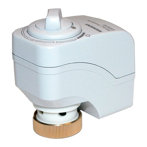
  9. Siemens GGA 1E Series User manual

Siemens GGA 1E Series User manual

74 319 0319 0
M4617
A
Lieferumfang
Deliverables
Contenu
Leverans
Leveringsomvang
Contenuto
Toimituslaajuus
Contenido
Leverancens omfang
B
Hinweise / Warnungen
Notes / Warnings
Indications / Mise en garde
Hänvisningar / Varningar
Aanwijzingen / Waarschuwingen
Messa in servizio / Indicazioni
Huomauksia / Varoituksia
Indicaciones / Consejos
Bemærkninger / Advarsler
de
Montageanleitung
Drehantrieb mit Federrücklauf
GGA...1E/..
en
Mounting instructions
Rotary-type spring return actuator
fr
Instructions de montage
Servo-moteur à action angulaire avec ressort de rappel
sv
Monteringsinstruktion
Spjällställdon med vridande rörelse och fjäderåtergång
nl
Montage-aanwijzing
Luchtklepservomotor voor veertuggang
it
Istruzioni di montaggio
Servocomando rotativo con emergenza in chiusura
fi
Asennusohje
Kiertoliikkeinen ilmapeltien toimimoottori
es
Instrucciones de montaje
Actuador de acción rotativa con muelle de retorno
da
Monteringsvejledning
Motor for drejebevægelse med spring return
Siemens Building Technologies 74 319 0319 0 f M4617 21-10-2014 1/8
de
sv
fi
Diese Anleitung ist beim Antrieb oder in der Anla-
gendokumentation aufzubewahren!
Dieses Symbol weist auf Gefahren und
Masnahmen zum Schutz von Personen und Sachen
hin:
•Antriebe für AC 230 V dürfen nur durch autorisier-
tes Personal angeschlossen werden.
•Zulässige Spannungen an den Hilfsschaltern:
Siehe Tabelle unter "Geräteschaltpläne".
•Die Anschlusskabel des Antriebs dürfen nicht im
Wasser liegen.
Denna instruktion skall förvaras tillsammans med
ställdonet eller anläggningsdokumentationen!
Denna symbol gäller riskfaktorer samt åtgärder
för att undvika person- och materialskador.
•Ställdon med AC 230 V får anslutas endast av
behörig personal.
•Tillåten spänning för hjälpkontakter, se tabellen i
avsnitt kopplingscheman.
•Ställdonets anslutningskabel får inte ligga i vatten.
Tätä ohjetta tulee säilyttää toimimoottorin
läheisyydessä tai yhdessä laitosdokumenttien
kanssa!
Tämä symboli viittaa vaaraan ja
toimenpiteisiin, joita tarvitaan henkilö- ja
aineellisten vahinkojen välttämiseksi:
•Ainoastaan valtuutetut ammattihenkilöt saavat
liittää 230 VAC:n toimimoottoreita.
•Sallitut jännitteet apukytkimissä: katso
"Kytkentäkaaviot"-kappaleessa oleva taulukko.
•Toimimoottorin liitäntäkaapelit eivät saa kastua
tai muuten altistua vedelle.
Gerät der Schutzklasse II (Schutzisolierung)
Apparat i isolerklass II (skyddsisolering)
Suojausluokan II laite (suoraerotus)
Gerät der Schutzklasse III (Schutzisolierung)
Apparat i isolerklass III (skyddsisolering)
Suojausluokan III laite (suojaerotus)
Achtung! Der Stellantrieb darf nicht geöffnet
werden
OBS! Ställdonet får inte öppnas.
Huomio! Toimimoottoria ei saa avata.
Federvorspannung
Werkseitig eingestellte Vorspannung: 5°.
Rückstellung
Elektrisch oder mechanisch.
Verdrahtung und Inbetriebnahme
Siehe in den anlagenspezifischen Unterlagen und in
der Basisdokumentation "Technische Grundlagen"
Z4613 zum Antrieb.
Fjäderförspänning
Fabriksinställd förspänning: 5°.
Återställning
Elekrisk eller mekanisk.
Elektrisk inkoppling och igångkörning
Se anläggningsspecifika underlag och grund-
läggande beskrivning “Handbok Z4613” för ställdonet.
Jousen esijännitys
Tehdasaseteltu esijännitys: 5°.
Palautus
Sähköisesti tai mekaanisesti.
Johdotus ja käyttöönotto
Katso laitoskohtaiset dokumentit ja toimimoottorin
tekninen käsikirja Z4613.
en
nl
es
Store these instructions together with the actua-
tor or with the plant documentation!
This symbol denotes dangers and measures to
avoid personal injury and property damage:
•Only authorized personnel may connect actuators
for AC 230 V.
•Refer to the table in "Diagrams" for the voltages
permissible at the auxiliary switches.
•Do not expose the actuator's connecting cables to
water or lay the cables in water.
Deze handleiding moet bij de servomotor, of met
de documentatie van de installatie worden
bewaard!
Dit symbool wijst op gevaar en maatregelen ter
bescherming van personen en materiaal:
•AC 230 V aandrijvingen mogen alleen door
bevoegd personeel worden aangesloten.
•Voor toelaatbare spanningen aan hulpschakelaars:
Zie tabel onder "Aansluitschema‘s"
•De aansluitkabel van de aandrijving mag niet in het
water liggen.
Conserve estas instrucciones con el actuador
o con la documentación de la instalación!
Este símbolo denota peligro y medidas para
evitar daños personales y de la propiedad:
•Sólo el personal autorizado puede conectar los
actuadores a 230 V CA.
•Consultar la tabla de "Conexionado eléctrico“
para saber la tensión permitida en los contactos
auxiliares
•No exponer los cables de conexión del actuador
al agua ni dejarlos en contacto con ésta.
Device of protection class II (protective
insulation)
Apparaat van beschermingsklasse II
(beschermings isolatie)
Equipo con tipo de protección II
(aislamiento protegido)
Device of protection class III (protective
insulation)
Apparaat van beschermingsklasse III
(beschermings isolatie)
Equipo con tipo de protección III
(aislamiento protegido)
Warning! Do not open the actuator.
Opgelet! De servomotor mag niet worden
geopend.
Atención! el actuador no debe ser
abierto.
Spring preload
Factory set preload: 5°.
Spring reset
By power or mechanical.
Wiring and commissioning
Refer to the actuator's commissioning instructions
and document "Technical basics" Z4613.
Vervoorspanning
Fabrieksmatig ingestelde voorspanning: 5°.
Terugloop
Elektrisch of mechanisch.
Bekabeling en inbedrijfstelling
Raadpleeg de installatie-documentatie en de
basisdocumentatie “technische grondslagen” Z4613
van de servomotor.
Compresión del muelle
Compresión de ajustado a fábrica: 5º.
Vuelta a cero
Eléctrica o mecánica.
Cableado y puesta en marcha
Ver la documentación técnica “Technical basics”
Z4613 del actuador.
fr
it
da
Cette instruction est à conserver avec le servo-
moteur ou avec la documentation de l’installation!
Ce symbole signale un danger pour les
personnes et les biens et les mesures y-afférentes :
•Le branchement des servomoteurs 230 V~ ne doit
être effectué que par un personnel qualifié.
•Tensions admissibles sur les contacts auxiliaires :
cf. "Schémas de raccordement"
•Les câbles de raccordement du servomoteur ne
doivent pas être en contact avec l'eau.
Queste istruzioni devono essere conservate con
la documentazione dell’impianto!
Questo simbolo indica – pericolo – il personale
deve fare attenzione per evitare ferite o danni.
•I collegamenti a 230 V CA . devono sempre essere
eseguiti da personale autorizzati.
•Fare riferimento alle “ tabelle tecniche“ per la
tensione ammessa per i contatti ausiliari.
•Non esporre all‘acqua il cavo ed i collegamentii
elettrici.
Opbevar denne vejledning sammen med moto-
ren eller med anlægsdokumentationen!
Dette symbol gør opmærksom på farer og
forholdsregler til beskyttelse af personer og gen-
stande:
•Motorer til AC 230 V må kun tilsluttes af
autoriserede personer.
•Tilladte spændinger til hjælpekontakter: Se
skema under "Apparatdiagrammer"
•Motorens tilslutningskabler må ikke ligge i vand.
Classe d'isolation II (isolation de protection)
Apparecchi di protezione classe ii
(protezione isolamento)
Apparat i isoleringsklasse II
(beskyttelsesisolering)
Classe d'isolation III (isolation de protection)
Apparecchio di protezione classe III
(protezione isolamento)
Apparat i isoleringsklasse III
(beskyttelsesisolering)
Attention! Le servo-moteur ne doit pas être
ouvert.
Attenzione! Il servocomando non deve
essere aperto.
OBS! Motoren må ikke åbnes.
Précontrainte du ressort
Précontrainte réglée à l’usine: 5°.
Remise à zéro
Electrique ou mécanique.
Câblage et mise en service
se référer à la documentation de l’installation et au
manuel technique Z4613 du servomoteur.
Precompressione della molla
Precompressione tarata in fabbrica: 5°.
Emergenza in chiusura
Elettrica o meccanica.
Collegamenti e messa in servizio
Consultare la documentazione per l’installazione e il
foglio tecnico (Z4613) del servocomando.
Fjederforspænding
Fabriksindstillet forspænding: 5°.
Tilbagestilling
Elektrisk eller mekanisk.
Eltilslutning og idriftsættelse
Se den anlægsspecifikke dokumentation samt
basisdokumentationen “Tekniske principper”
Z4613 for motoren.
2/8 21-10-2014 74 319 0319 0 f Siemens Building Technologies
C
Montage auf Klappenachse
Shaft mounting
Montage sur l’axe des volets
Montering på spjällaxel
Montage op de luchtklepas
Montaggio all’asse della serranda
Asennus pellin akseliin
Montaje sobre el eje de las comp.
Montering på spjældaksel
Siemens Building Technologies 74 319 0319 0 f M4617 21-10-2014 3/8
D
Manuelle Verstellung
Manual adjustment
Positionnement manuel
Manuell justering
Handmatige verstelling
Posizionamento manuale
Käsiohjaus
Posicionamiento manual
Manuel justering
•verstellen •sperren •entriegeln
•adjustment •locking •releasing
•positionner •verrouiller •débloquer
•justera •blockera •återställa
•verstellen •blokkeren •ontgrendelen
•posizione •bloccare •sbloccare
•käsisäätö •lukitus •vapautus
•psicionar •boquear •dsbloquear
•justere •låse •frigøre
4617Z24
GEARTRAIN
LOCK PIN
7
89
3
4
x 7¾ = 90°
90°
click !
6
5
Hold
GEARTRAIN
LOCK PIN
h
3 mm
21
GEARTRAIN
LOCK PIN
4/8 21-10-2014 74 319 0319 0 f Siemens Building Technologies
E
Massbild
Dimensions
Encombrement
Måttuppgift
Maatschets
Ingombri
Mittapiirros
Dimensiones
Målskitse
36
65
264
174
85
100
67.5
71
4617Z27
Masse in mm
Mått i mm
Mitat mm
Dimensions in mm
Afmetingen in mm
Dimensiones en mm
Dimensions en mm
Dimensioni in mm
Mål i mm
fi
LED toimita
Punainen = Käyttöjännite OK
Lämpöanturi viallinen
Vihreä = Käyttöjännite OK
Lämpöanturi OK
Ei pala = Ei käyttöjännitettä
es
Funciones LED
Rojo = Voltaje de operación OK
Sonda térmica por defecto
Verde = Voltaje de operación OK
Sonda térmica OK
Oscuro = Sin voltaje de operación
da
Indikatorfunktioner
Rød = Driftsspænding OK
Termostatføler defekt
Grøn = Driftsspænding OK
Termostatføler OK
Mørk = Ingen driftsspænding
de
LED-Funktion
rot = Betriebsspannung i. O.
Thermosensor defekt
grün = Betriebsspannung i. O.
Thermosensor i. O.
dunkel = keine Betriebsspannung
en
LED functions
Red = Operating voltage OK
Thermo sensor defect
Green = Operating voltage OK
Thermo sensor OK
Dark = No operating voltage
fr
Fonctions de la LED
Rouge = Tension OK
Sonde défectueuse
Verte = Tension OK
Sonde OK
Eteinte = Absence de tension
sv
Lysdiodfunktioner
Röd = Matningsspänning OK
Termogivare defekt
Grön = Matningsspänning OK
Termogivare OK
Mörk = Ingen matningsspänning
nl
LED functies
Rood = Voedingspanning OK
Thermo sensor defect
Groen = Voedingspanning OK
Thermo sensor OK
Donker = Geen voedingspanning
it
LED funzioni
Rosso = Alimentazione OK
Sensore difettoso
Verde = Alimentazione OK
Sensore OK
Spento = Mancanza alimentazione
Siemens Building Technologies 74 319 0319 0 f M4617 21-10-2014 5/8
F
Geräteschaltpläne
Wiring diagrams
Schémas de raccordement
Kopplingsscheman
Aansluitschema’s
Schemi di collegamento
Kytkentäkaaviot
Conexionado eléctrico
Apparatdiagrammer
GGA126.1E/T..
AC 24 V / DC 24…48 V
Zweipunkt-Steuerung
Two-position control
Commande tout ou rien
Tvåläges styrning
Tweepuntsbesturing
Comando a 2 posizioni
Kaksipisteohjaus
Control a 2 puntos
On/off-styring
GGA326.1E/T..
AC 230 V
Zweipunkt-Steuerung
Two-position control
Commande tout ou rien
Tvåläges styrning
Tweepuntsbesturing
Comando a 2 posizioni
Kaksipisteohjaus
Control a 2 puntos
On/off-styring
Voltage
Switch A (S1)
Switch B (S4)
ok / no!
AC 24 V
AC 24 V
AC 24 V
ok
AC 230 V L1 (phase)
L2
L3
LX (phase)
L1 (phase)
L2
L3
≠
LX(phase)
ok
ok
ok
no!
mixed AC 24 V
AC 230 V
AC 230 V
AC 24 V
no!
no!
6/8 21-10-2014 74 319 0319 0 f Siemens Building Technologies
de
Kabelbezeichnungen Anschluss Kabel Bedeutung
Code Nr. Farbe Akürzung
Antriebe
G
1
rot
RD
System Potential AC 24 V / DC 24…48 V
AC 24 V
DC 24…48 V G0 2 schwarz BK Systemnull
Antriebe
L
3
braun
BN
Phase AC 230 V
AC 230 V N 4 blau BU Nullleiter
Hilfsschalter
Q11
S1
grau/rot
GYRD
Schalter A Eingang
Q12 S2 grau/blau GYBU Schalter A Ruhekontakt
Q14
S3
grau/rosa
GYPK
Schalter A Schliesskontakt
Q21
S4
schwarz/rot
BKRD
Schalter B Eingang
Q22
S5
schwarz/blau
BKBU
Schalter B Ruhekontakt
Q24
S6
schwarz/rosa
BKPK
Schalter B Schliesskontakt
en
Wire designations Connecton Cable Meaning
Code No. Color Abbreviation
Actuators
G
1
red
RD
System potential AC 24 V / DC 24…48 V
AC 24 V
DC 24…48 V
G0 2 black BK System neutral
Actuators
L
3
brown
BN
Line AC 230 V
AC 230 V
N
4
blue
BU
Neutral
Auxiliary
Q11
S1
grey/red
GYRD
Switch A input
switch
Q12
S2
grey/blue
GYBU
Switch A normally-closed contact
Q14 S3 grey/pink GYPK Switch A normally-open contact
Q21
S4
black/red
BKRD
Switch B input
Q22
S5
black/blue
BKBU
Switch B normally-closed contact
Q24 S6 black/pink BKPK Switch B normally-open contact
fr
Désignation des câbles Câbles de
raccordement
Câble Signification
Code No. Couleurs Abbreviation
Servo-moteurs G 1 rouge RD Potentiel du système AC 24 V / DC 24…48 V
AC 24 V
DC 24…48 V G0 2 noir BK Zéro du système
Servo-moteurs
L
3
brun
BN
Phase AC 230 V
AC 230 V N 4 bleu BU Neutre
Commutateurs
Q11
S1
gris/rouge
GYRD
Commutateur A entrée
auxiliaires Q12 S2 gris/bleu GYBU Commutateur A contact de repos
Q14
S3
gris/rose
GYPK
Commutateur A contact de travail
Q21
S4
noir/rouge
BKRD
Commutateur B entrée
Q22 S5 noir/bleu BKBU Commutateur B contact de repos
Q24
S6
noir/rose
BKPK
Commutateur B contact de travail
Siemens Building Technologies 74 319 0319 0 f M4617 21-10-2014 7/8
Siemens Switzerland Ltd, 2005 Subject to alteration
8/8 21-10-2014 74 319 0319 0 f Siemens Building Technologies
Other Siemens Controllers manuals

Siemens Simatic S7-1500 User manual

Siemens

Siemens Simatic S7-1500 User manual

Siemens SINUMERIK 840Di User manual

Siemens

Siemens SINUMERIK 840Di User manual

Siemens RVP201 Operator's manual

Siemens

Siemens RVP201 Operator's manual

Siemens Simatic S7-1500 User manual

Siemens

Siemens Simatic S7-1500 User manual

Siemens OpenAir G..B181.1E/KN Series Installation guide

Siemens

Siemens OpenAir G..B181.1E/KN Series Installation guide

Siemens LMV27.100x2 Operator's manual

Siemens

Siemens LMV27.100x2 Operator's manual

Siemens RLM162 User manual

Siemens

Siemens RLM162 User manual

Siemens SIRIUS 3RM10 Series User manual

Siemens

Siemens SIRIUS 3RM10 Series User manual

Siemens Acvatix SAX Series Operator's manual

Siemens

Siemens Acvatix SAX Series Operator's manual

Siemens Flowrite 599 Series User manual

Siemens

Siemens Flowrite 599 Series User manual

Siemens SIMOTION P320-4 E User manual

Siemens

Siemens SIMOTION P320-4 E User manual

Siemens SKB32 Series User manual

Siemens

Siemens SKB32 Series User manual

Siemens Simatic S7-1500 User manual

Siemens

Siemens Simatic S7-1500 User manual

Siemens SINAMICS S120 Parts list manual

Siemens

Siemens SINAMICS S120 Parts list manual

Siemens SIMATIC S5-115U User manual

Siemens

Siemens SIMATIC S5-115U User manual

Siemens SIMATIC S5-100U User guide

Siemens

Siemens SIMATIC S5-100U User guide

Siemens IQHeat User manual

Siemens

Siemens IQHeat User manual

Siemens OpenAir GLB Series User manual

Siemens

Siemens OpenAir GLB Series User manual

Siemens Simatic S7-300 User manual

Siemens

Siemens Simatic S7-300 User manual

Siemens Ertec 400 User manual

Siemens

Siemens Ertec 400 User manual

Siemens SITRANS LUT400 User manual

Siemens

Siemens SITRANS LUT400 User manual

Siemens SIRIUS 3RF29 0-0KA Series User manual

Siemens

Siemens SIRIUS 3RF29 0-0KA Series User manual

Siemens scalance WLC711 Operating manual

Siemens

Siemens scalance WLC711 Operating manual

Siemens LMO39 Series Operator's manual

Siemens

Siemens LMO39 Series Operator's manual

Popular Controllers manuals by other brands

SMSC USB2640i datasheet

SMSC

SMSC USB2640i datasheet

Black Stone BL 983313-0 instruction manual

Black Stone

Black Stone BL 983313-0 instruction manual

Burkert Positioner TopControl Basic quick start

Burkert

Burkert Positioner TopControl Basic quick start

Wittenstein TPM dynamic operating manual

Wittenstein

Wittenstein TPM dynamic operating manual

Chauvet LX GO user manual

Chauvet

Chauvet LX GO user manual

Danfoss EIM 336 manual

Danfoss

Danfoss EIM 336 manual

Honeywell Home HR92 user guide

Honeywell Home

Honeywell Home HR92 user guide

eZLO Atom Advanced information

eZLO

eZLO Atom Advanced information

Mercury Security EP1501 quick start guide

Mercury Security

Mercury Security EP1501 quick start guide

Balmar Max Charge MC-614-H Installation and operation manual

Balmar

Balmar Max Charge MC-614-H Installation and operation manual

Vacon NXP Hardware manual

Vacon

Vacon NXP Hardware manual

Fairford Dfe series installation instructions

Fairford

Fairford Dfe series installation instructions

NEW BRUNSWICK SCIENTIFIC Scale Interface Box Guide to operations

NEW BRUNSWICK SCIENTIFIC

NEW BRUNSWICK SCIENTIFIC Scale Interface Box Guide to operations

zeeltronic PCDI-RGT user manual

zeeltronic

zeeltronic PCDI-RGT user manual

Omron sysmac EtherNet/IP NJ Series Connection guide

Omron

Omron sysmac EtherNet/IP NJ Series Connection guide

YASKAWA V1000 Series Installation & start-up manual

YASKAWA

YASKAWA V1000 Series Installation & start-up manual

Johnson Controls CK721-A Installation and operation manual

Johnson Controls

Johnson Controls CK721-A Installation and operation manual

GRAIGAR R448 Installation and Maintenance

GRAIGAR

GRAIGAR R448 Installation and Maintenance

manuals.online logo
manuals.online logoBrands
  • About & Mission
  • Contact us
  • Privacy Policy
  • Terms and Conditions

Copyright 2025 Manuals.Online. All Rights Reserved.