Aulisa Guardian Angel GA1000 Series User manual

Digital Vital Sign Monitoring System
Instructions For Use
____________________________________________________________
7MN00026-01
Guardian Angel®
GA1000 Series

1
Disclaimer
At the time of publication, this manual is believed to be accurate and up-to-date. In
the interest of continued product development, Taiwan Aulisa Medical Devices
Technologies, Inc. reserves the right to make changes and improvements to this
manual and the products described within at any time, without notice or obligation.
References to “Aulisa” in this manual shall imply Taiwan Aulisa Medical Devices
Technologies, Inc.
Aulisa is a registered trademark of Taiwan Aulisa Medical Devices Technologies, Inc.
Taiwan Aulisa Medical Devices Technologies, Inc.
No. 218-2, Chong Yang Rd., Nangang Dist.
11573 Taipei City , Taiwan
Tel.:+886 809 083 100
Distributed by
Aulisa Medical USA, Inc.
999 Commercial Street, Suite 208
Palo Alto, CA 94303,USA
Tel.: 1.833.828.5472
www.aulisa.com
© 2020 Taiwan Aulisa Medical Devices Technologies, Inc.
CAUTION!!! Read this entire manual carefully before using Guardian Angel®GA1000
Series Digital Vital Sign Monitoring System.

2
Table of Contents
Disclaimer.......................................................................................................................1
Guide to Symbols ...........................................................................................................3
Welcome ........................................................................................................................5
GA1000S Main Elements........................................................................................5
GA1000S Function..................................................................................................6
GA1000S Intended Use ..........................................................................................6
Precautions for Use........................................................................................................7
Device Components .......................................................................................................8
Device Overview ............................................................................................................9
Device Setting Up.........................................................................................................14
Device Pairing...............................................................................................................15
Automatic Pairing.................................................................................................15
Pairing with a new Aulisa sensor module............................................................15
Device Verification .......................................................................................................16
Verify the device function....................................................................................16
Verify the alarm function BEFORE each use ........................................................16
Device Power Off..........................................................................................................17
Device Powering...........................................................................................................17
Alarms and Limits.........................................................................................................18
Alarm Features.....................................................................................................18
Alarm Limits .........................................................................................................22
Alarm Delay Feature (for Oximeter Module only) ...............................................26
Care and Maintenance.................................................................................................27
Troubleshooting ...........................................................................................................28
FCC Compliance ...........................................................................................................29
Service, Support, and Warranty...................................................................................31
Privacy Policy................................................................................................................32
Our Policy .............................................................................................................32
Changes................................................................................................................33
Specifications ...............................................................................................................40
Parts and Accessories...................................................................................................41

3
Guide to Symbols

4

5
Welcome
This manual will help you get started with monitoring using Aulisa Guardian Angel®
GA1000 Series Digital Vital Sign Monitoring System (“GA1000S”) by introducing the
Display Unit which is intended for use in conjunction with a variety of wearable
Aulisa sensor modules.
Refer to the Instructions for Use of Aulisa sensor module(s) for detailed instructions.
Adult/Pediatric Oximeter Module: 7MN00028-01
Infant Oximeter Module: 7MN00029-01
Thermometer Module: 7MN00030-01
GA1000S Main Elements
Display Unit – A self-contained tablet computer running Aulisa application
software wirelessly collects and displays vital sign data from the Aulisa sensor
module(s). It also generates alarms to alert users to technical errors or
physiological events.
Adult/Pediatric Oximeter Module – A wireless and reusable device worn on the
finger measures and transmits SpO2and pulse rate data. It is composed of
Oximeter Box and Oximeter Sensor Cable.
Infant Oximeter Module – A wireless and reusable device worn on the foot
measures and transmits SpO2and pulse rate data.
Thermometer Module –An adhesive device attached to the chest and armpit
measures and transmits body temperature data wirelessly. It comprises
Thermometer Box and Sensor Patch. It is intended for adults, pediatrics, and
infants.

6
GA1000S Function
The Aulisa sensor module(s) is a wearable device intended for vital signs detection
and physiological data transmission to the Display Unit via Bluetooth technology. The
Display Unit receives and displays physiological data as well as generates alarms for
technical errors or physiological events.
GA1000S Intended Use
The Guardian Angel® GA1000 Series Digital Vital Sign Monitoring System is intended
to help those who are interested in keeping watch on oxygen saturation level (SpO2),
pulse rate (PR) and armpit body temperature of their loved ones. The Guardian Angel
is not intended for medical use.
Aulisa sensor module(s)
NOTE: The GA1000S may come with different Aulisa sensor module(s) resulting in
different intended uses.
Display unit

7
Precautions for Use
1. Use this device only within its designated range (approximately 32.8 feet (10
meters)— spherical radius— from Aulisa sensor module(s) to this device).
Moving outside this range may cause missing, lost, and/or inaccurate data.
2. This device readings may be affected by the use of an electrosurgical unit.
3. If this device fails to respond as described, discontinue use until the situation is
corrected by qualified personnel.
4. Be careful with small parts that can be removed from the device and swallowed,
such as port covers. They are hazardous to children.
5. Do not use in or around water or any other liquid when AC power adaptor is
used.
6. Only use this device with charging adaptors provided by Aulisa.
7. Do not immerse any part of the device in any liquids.
8. Do not subject the device to extreme hot or cold temperatures, humidity, or
direct sunlight.
9. Follow local governing ordinances and recycling instructions regarding disposal
or recycling of the device and device components, including batteries.
10. Radios and cell phones or similar devices can affect the wireless connection of
the device and must be kept at least 6.5 feet (2 meters) away from the device.
11. System connection failure (Bluetooth wireless connection) may result in loss of
data tran sfe r.
8
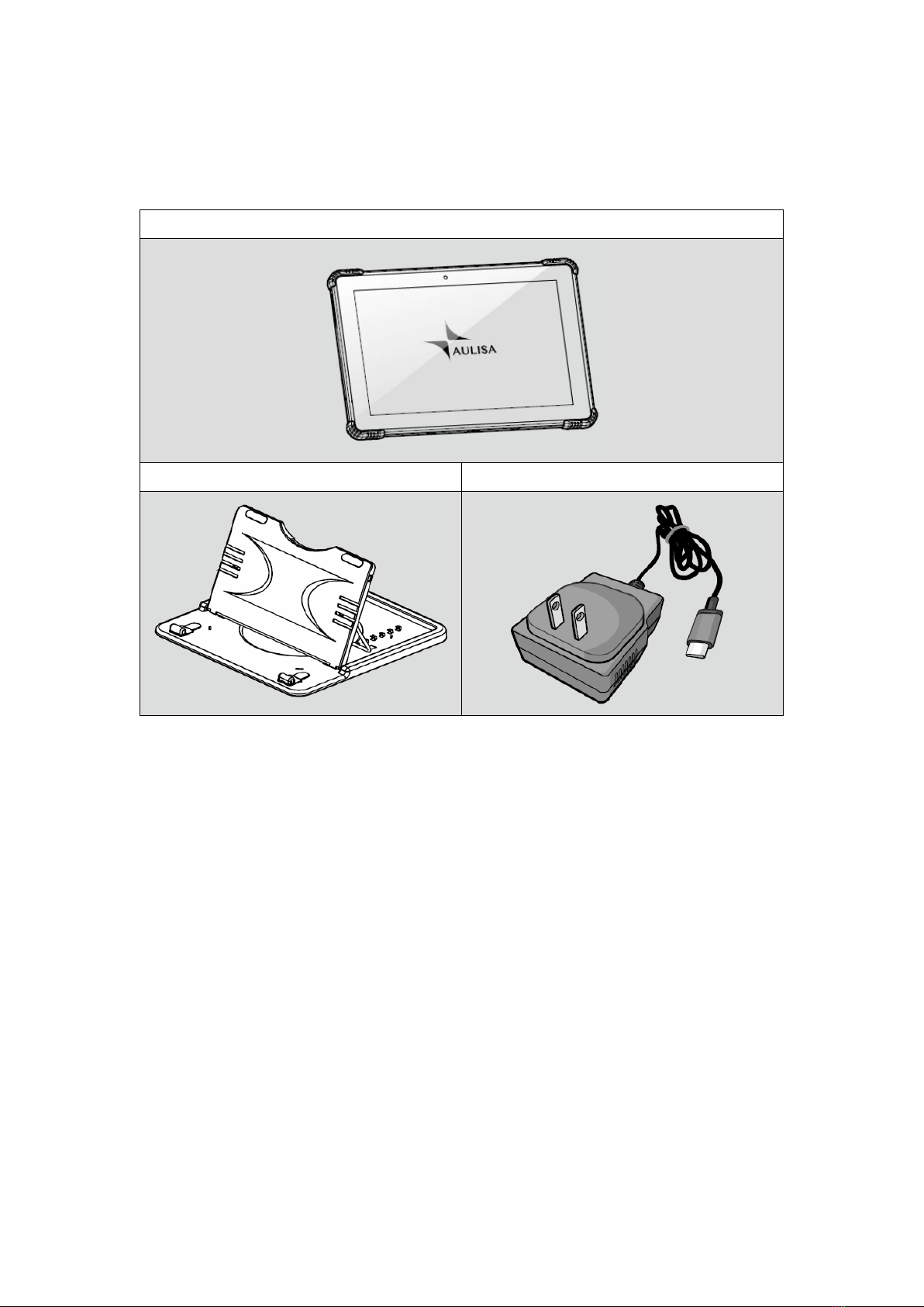
Device Components
Display Unit with Aulisa application software
Display Unit Stand Display Unit Charging Adapter (Type-C)

9
Device Overview
The Display Unit features a 10 1" LCD multi-touch display with Bluetooth technology.
The Display Unit displays real-time vital signs measured by Aulisa sensor module(s).
The Display Unit will display informational text messages, alarm text messages, and
beep made audible upon an alarm condition trigger event.
Following tables describe the indicators and controls displayed on the Display Unit.
Display Icons and Indicators
Indicator
Name
Description
SpO
2
%
Blood Oxygen
This icon identifies the window
showing the functional blood
oxygen saturation in percent.
PR bpm
Pulse Rate
This icon identifies the window
showing the pulse rate in bpm.
TEMP°F
Body Temperature
This icon identifies the window
showing the body temperature
in either
°C or °F.
Hi
High temperature
Displayed when the measured
temperature is higher than
107.6°F (42.0°C).
NOTE: It is recommended that the Display Unit be placed on the Display Unit Stand.
NOTE: Close the cover of charging port when the charging adapter is not in use.

10
Lo
Low temperature
Displayed when the measured
temperature is lower than
89.6°F (32.0°C).
No data
When the vital signs cannot be
measured, the Display Unit
shows dashes “- - -” in each of
the vital sign windows.
Bluetooth
Connection Status
This icon displays whether the
Aulisa sensor module(s) and the
Display Unit are connected via
Bluetooth. It will turn blue once
the pairing succeeds.
Pulse Amplitude
(PA)
This icon displays the pulse
signal strength.
Measurement Site
Status
This icon displays whether
there is a finger inserted in the
Adult/Pediatric Oximeter
Module.
A system alarm will be
displayed on the Display Unit if
no fingers are detected.
Measurement
Site Status
This icon displays whether the
Infant Oximeter Module is
attached to the foot. A system
alarm will be displayed on the
Display Unit if no contact is
detected between the sensor
and the foot.
Motion Indicator
This animated icon detects
excessive motion of the
measurement site.
Sensor Cable
Connection Status
This icon indicates whether the
Oximeter Sensor Cable is
connected to the Oximeter Box.
A system alarm will be
displayed on the Display Unit if
11
the cable is disconnected.
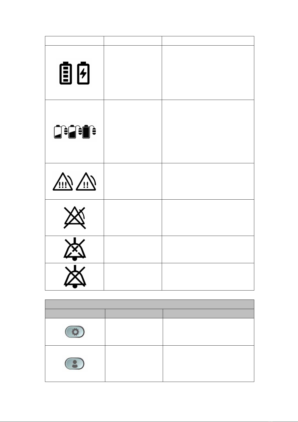
Battery Level of
Display Unit
These icons signify the battery
level of the Display Unit.
A medium priority system alarm
will be displayed on the Display
Unit when the Display Unit
battery level is low.
Battery Level of
Aulisa sensor
module(s)
These icons signify the battery
level of Aulisa sensor module(s)
at Full, Medium, or Low.
A medium priority system alarm
will be displayed on the Display
Unit when the battery level is
low.
Alarm Indicator
This icon identifies an alarm
condition exists.
“!!!” represents high priority.
“!!” represents medium priority.
Alarm Off
This icon indicates that the
alarm is turned off for the
corresponding physiological
condition.
Audio Paused
This icon indicates that the
alarm audio is silenced for 2
minutes.
Audio Off
This icon indicates that the
alarm audio is silenced
permanently.
Software Control Buttons
Button
Function
Description
System Settings
Tap on this button on the MAIN
screen to access the setting
menu of the system.
Edit Profile
Tap on this button on the MAIN
screen to edit profile, including
name, weight, gender, date of
birth, and location.
12
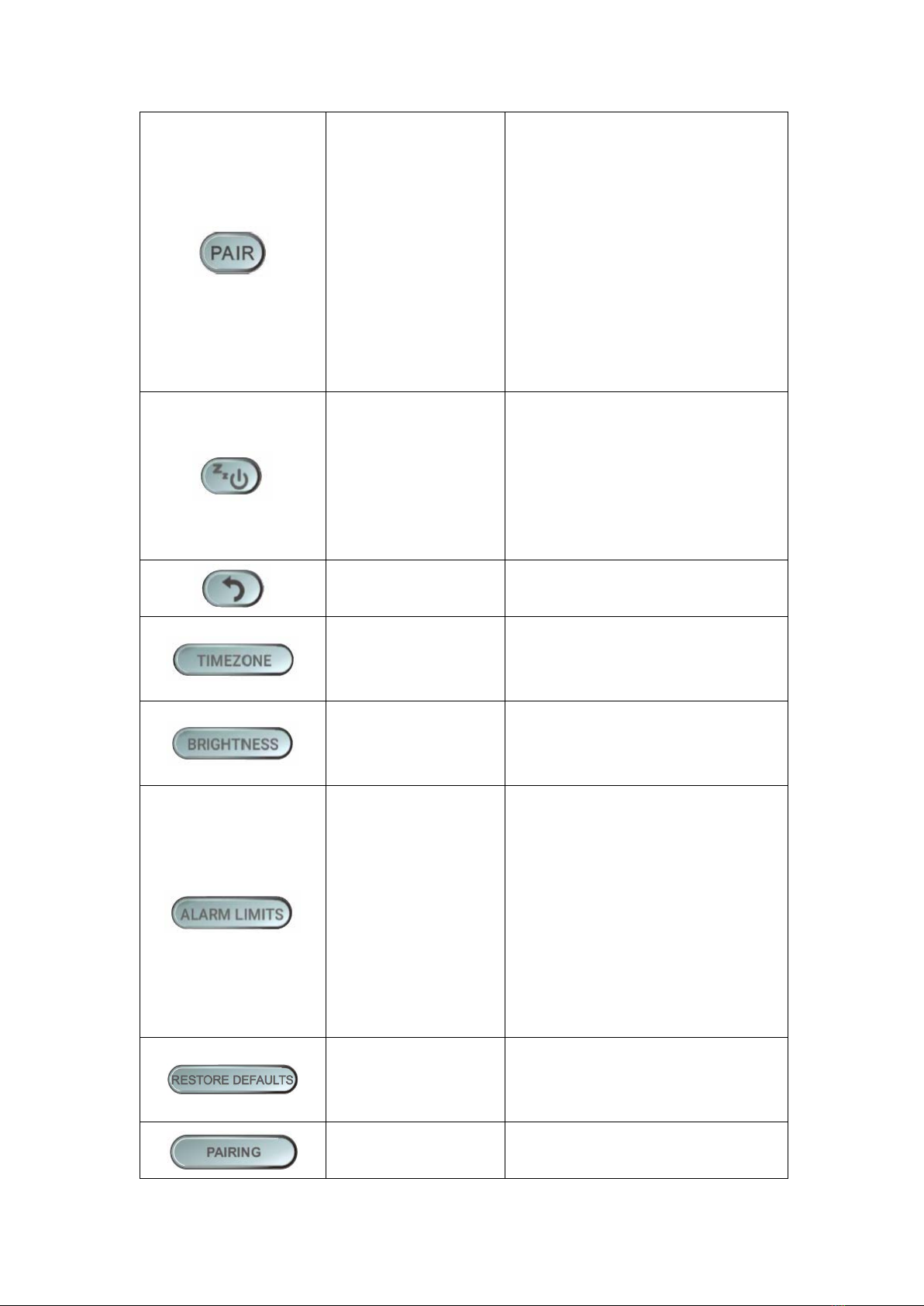
Device Pairing
This button appears on the
MAIN screen when the system
is disconnected. Tap on the
button to force the
system to pair.
NOTE: The Aulisa sensor
module(s) must be placed
within 32.8 feet (10 meters) to
the Display Unit.
Sleep Mode
Tap on this button on the MAIN
screen to let the Display Unit
enter sleep mode. To wake up
the Display Unit, tap on the
blank screen and use finger to
swipe to the right.
Return to Previous
Screen
Tap on this button to return to
the previous page.
Set Timezone
In the Setting menu,
tap on this
button to select the correct
timezone.
Set Display
Brightness
In the Setting menu,
tap on this
button to set the brightness of
the display.
Set Alarm Limits
In the Setting menu,
t
ap on this
button to adjust the alarm
limits for each Aulisa sensor
module.
NOTE: The alarm limits are
adjustable only when the
wireless connection is
established.
Restore Default
Alarm Settings
Tap on this button to restore
alarm limits to manufacture-
configured values.
Establish Pairing
In the Setting menu,
tap on this
button and scan the barcode
13
on the
Aulisa sensor module
(s)
to manually pair with the
Display Unit.
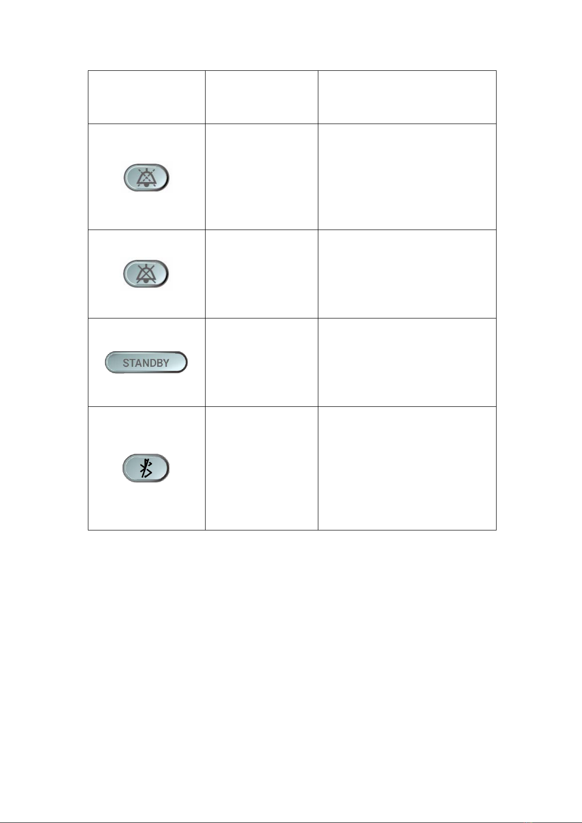
Pause Alarm Audio
This button appears when an
alarm is triggered. Tap on the
button to
temporarily
silence
the alarm audio of the current
triggered alarm event for 2
minutes.
Turn Off Alarm
Audio
The button appears when an
alarm is triggered. Tap on the
button to
permanently
silence
the alarm audio of the current
triggered alarm event.
Standby
The button appears when the
Infant Oximeter Module is
detached from the foot. Tap
on the button to return to the
“Before You Start” page.
Clear Bluetooth
Alarm Condition
The button appears when the
Bluetooth is disconnected and
the alarm is triggered. Tap on
the button to clear the alarm
of “BLUETOOTH
DISCONNECTED OR POWER
OFF”.

14
Device Setting Up
Before you begin your monitoring session, unpack the Display Unit and become
familiar with its parts.
Step 1: Set up the Aulisa sensor module(s).
Step 2: Connect the charging adaptor to the Display Unit and a power outlet.
Step 3: Press and hold the Power button for at least three (3) seconds to turn on the
Display Unit.
Step 4: Wait for the wireless connection between the Display Unit and the Aulisa
sensor module(s) to be established. Once connected, the vital signs and the
Aulisa sensor module(s) status information will appear on the MAIN screen.
NOTE: Refer to the Aulisa sensor module(s) Instructions for Use for setting up
instructions.
CAUTION!!! Always keep the Display Unit plugged in.
CAUTION!!! Do not plug the adaptor into a switched outlet to prevent accidental
switching power off.
NOTE: Refer to “Device Pairing” section below for more information.
NOTE: The Aulisa sensor module(s) must be used within 32.8 feet (10 meters) to the
Display Unit.
NOTE: The Bluetooth connection status icon will turn blue once the pairing succeeds.
NOTE: Verify System Operation before use. (See “Device Verification” section for more
information.)

15
Device Pairing
Automatic Pairing
The Display Unit automatically detects and connects to the Aulisa sensor module(s)
from the same starter kit. If the Bluetooth connection is not established
automatically, press "PAIR" button on the MAIN screen of the Display Unit to force
the system to pair.
Pairing with a new Aulisa sensor module
Follow the below instructions to manually set up the pairing of a new Aulisa sensor
module.
Step 1: In the Setting menu, select “PAIRING".
Step 2: Scan the QR Code or key in the serial number located on the Aulisa sensor
module(s).
Step 3: Press “CONFIRM” if the serial number (SN) displayed matches with the one
on the Aulisa sensor module(s).
Step 4: Power on the designated Aulisa sensor module(s).
Step 5: To confirm that the process was successful, ensure that the Bluetooth
connection status icon on the MAIN screen of the Display Unit is lit blue.
NOTE: The Aulisa sensor module(s) must be placed within 32.8 feet (10 meters) to the
Display Unit.
NOTE: The Bluetooth connection status icon will turn blue once the pairing succeeds.
NOTE: The power LED on the Aulisa sensor module(s) will blink green when pairing
succeeds, and data transmission starts.
NOTE: The Aulisa sensor module(s) remains paired with the Display Unit until the serial
number is deleted from the list.
NOTE: The power LED on the Aulisa sensor module(s) lights green when the power is
ON.

16
Device Verification
Verify the device function
Step 1: Set up the system. Refer to the Aulisa sensor module(s) Instructions for Use
for setting up instructions.
Step 2: Make sure Aulisa sensor module(s) is worn on or attached to the right place
firmly.
Step 3: Verify that the Bluetooth connection status icon on the Display Unit is blue
and the status indicator on Aulisa sensor module(s) is blinking green.
Step 4: Verify that the vital sign readings are displayed.
Verify the alarm function BEFORE each use
Step 1: Set up the system. Refer to the Aulisa sensor module(s) Instructions for Use
for setting up instructions.
Step 2: Ensure the Bluetooth connection is established. (See “Device Pairing”
section.)
Step 3: Set the alarm limit lower or higher than the displayed value.
Step 4: Verify that an alarm message is displayed and that an alarm audio is
generated. (See “Troubleshooting” section if an alarm message and audio
signal is not generated.)
Step 5: Press on the "PAUSE AUDIO" button to temporarily silence for 2 minutes.
Step 6: After alarm signal is regenerated, press on the "AUDIO OFF" button to
silence permanently the alarm signal.

17
Device Power Off
Step 1: Press the Power button for at least three (3) seconds until a message
displayed.
Step 2: Choose “Power off” to turn off the Display Unit.
Device Powering
The Display Unit is meant to be used with the charging adaptor ALWAYS plugged in. If
the Display Unit is disconnected from the charging adaptor accidentally, proceed
with the following steps to charge and power the Display Unit. The Display Unit will
alert the user when the Display Unit itself is low on battery.
Step 1: Plug the Type-C end of the charging adaptor into the Display Unit.
Step 2: Attach the wall adaptor to a power outlet.
Step 3: Place the Display Unit on the stand provided.
NOTE: You may also tap on the “SLEEP” button to enter the sleep mode.
CAUTION!!! Only use adaptors supplied or manufactured by Taiwan Aulisa Medical
Devices Technologies, Inc.
18
Alarms and Limits
Alarm Features
The Display Unit provides high and medium priority audible and visual alarms. The
visual alarm is indicated by the alarm window on the screen of the Display Unit.
Audio alarms will sound from the speakers on the Display Unit.
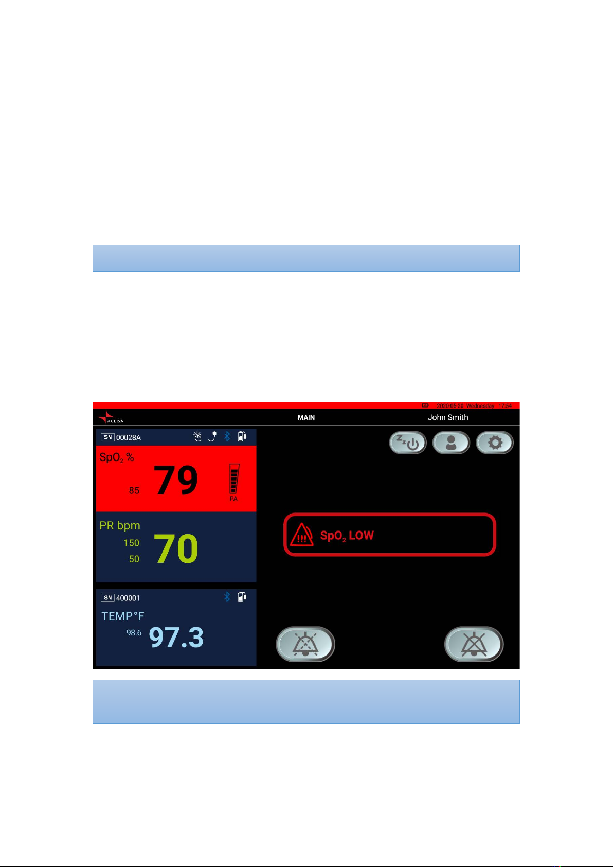
High Priority Alarms
High priority alarms are those that require immediate attention to the person
being monitored, including SpO2, pulse rate, and temperature alarms. On the
Display Unit, high priority alarms are indicated with rapid blinking vital sign
readings in red color and with alarm text message when alarm limits are met or
exceeded. (See figure below.)
NOTE: Alarm LED indicator on the Oximeter Module will blink red along with displays
on the Display Unit.
NOTE: The volume for audio alarms cannot be adjusted.
19
High priority audio alarms are: 3 beeps, short pause, 2 beeps, short pause, 3
beeps, short pause, 2 beeps, and 5-second pause. This sequence repeats until
the alarm is cleared or silenced.
Tap on ʻʻPAUSE AUDIOʼʼ button to pause the alarm audio for 2 minutes. Tap on
ʻʻAUDIO OFFʼʼ button to permanently silence the alarm audio.
See “Alarm Limits” section to learn adjusting the alarm limit.
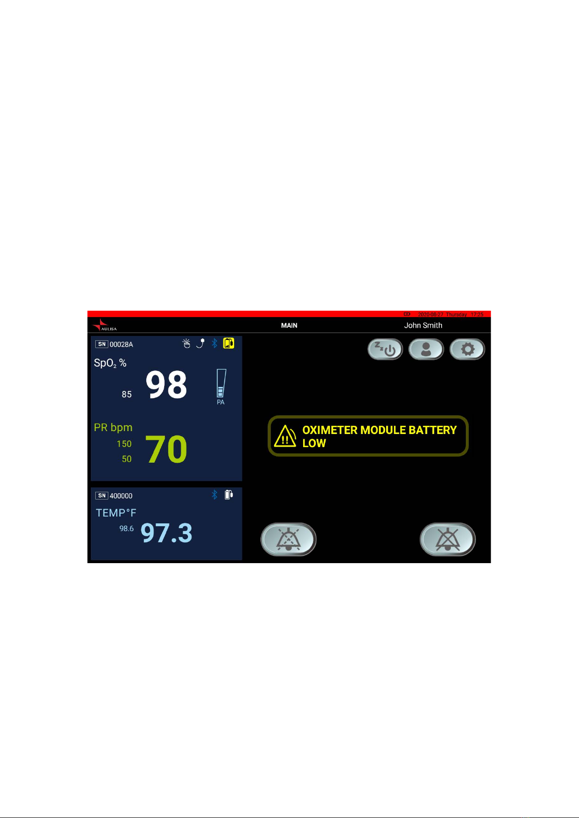
Medium Priority Alarms
Medium priority alarms are those that signal potential problems with the
equipment or other non-life-threatening situations. On the Display Unit, medium
priority alarms are indicated with slow blinking yellow displays and with alarm
text message. (See figure below.)
Other manuals for Guardian Angel GA1000 Series
2
This manual suits for next models
1
Table of contents
Popular Measuring Instrument manuals by other brands


Triacta
Triacta PowerHawk 6212 installation guide

Liquid Controls
Liquid Controls LectroCount3 Installation procedures

Blue-White
Blue-White FLEXFLO M4 Series operating manual

Siargo
Siargo MF5700 Series user manual

Vibrock
Vibrock V9000 Operator's manual

Hanna Instruments
Hanna Instruments HI96726 instruction manual