Aulisa Guardian Angel GA1000 Series User manual

Instructions For Use
____________________________________________________________
7MN00028-01
Guardian Angel®
Adult/Pediatric Oximeter Module

1
Disclaimer
At the time of publication, this manual is believed to be accurate and up-to-date. In
the interest of continued product development, Taiwan Aulisa Medical Devices
Technologies, Inc. reserves the right to make changes and improvements to this
manual and the products described within at any time, without notice or obligation.
References to “Aulisa” in this manual shall imply Taiwan Aulisa Medical Devices
Technologies, Inc.
Aulisa is a registered trademark of Taiwan Aulisa Medical Devices Technologies, Inc.
Taiwan Aulisa Medical Devices Technologies, Inc.
No. 218-2, Chong Yang Rd., Nangang Dist.
11573 Taipei City , Taiwan
Tel.: +886 809 083 100
Distributed by
Aulisa Medical USA, Inc.
999 Commercial Street, Suite 208
Palo Alto, CA 94303,USA
Tel.: 1.833.828.5472
www.aulisa.com
© 2020 Taiwan Aulisa Medical Devices Technologies, Inc.
CAUTION!!! Read this entire manual carefully before using Guardian Angel® Digital Vital
Sign Monitoring System.

2
Table of Contents
Disclaimer.......................................................................................................................1
Guide to Symbols ...........................................................................................................3
Welcome ........................................................................................................................5
Precautions for Use........................................................................................................5
Warnings ................................................................................................................5
Cautions .................................................................................................................6
Device Overview ............................................................................................................8
Device Components ...............................................................................................8
Device Description .................................................................................................9
Device Intended Use ............................................................................................10
Device Principle of Operation ..............................................................................10
Device Setting Up.........................................................................................................10
Device Pairing...............................................................................................................13
Automatic Pairing.................................................................................................13
Manual Pairing .....................................................................................................13
Device Power Off..........................................................................................................15
Device Charging............................................................................................................15
Alarms ..........................................................................................................................16
Care and Maintenance.................................................................................................16
Cleaning and Disinfection ....................................................................................16
Troubleshooting ...........................................................................................................17
FCC Compliance ...........................................................................................................19
Service, Support, and Warranty...................................................................................21
Privacy Policy................................................................................................................22
Our Policy .............................................................................................................22
Changes................................................................................................................23
Specifications ...............................................................................................................30
Parts and Accessories...................................................................................................31

3
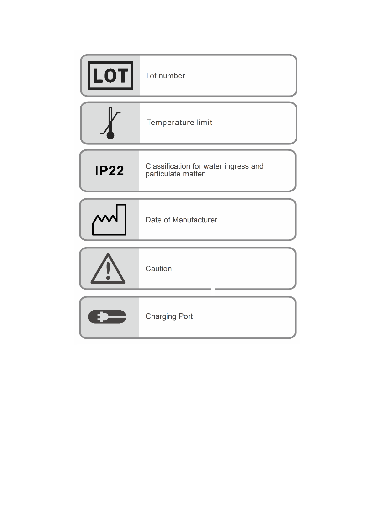
Guide to Symbols
4

5
Welcome
This manual will help you get started with monitoring using the Adult/Pediatric
Oximeter Module of Aulisa Guardian Angel® Digital Vital Sign Monitoring System.
GA1000 Series
The Oximeter Module is intended for use with the Display Unit. Refer to the GA1000
Series Instructions for Use (7MN00026-01) for detailed instructions.
GA2000 Series
The Oximeter Module is intended for use with the Display Unit and
Receiver/Transponder. Refer to the GA2000 Series Instructions for Use (7MN00027-
01) for detailed instructions.
Precautions for Use
Warnings
1. Anemia may affect the accuracy of the measurement.
2. Only use the sensor cables manufactured by Aulisa. These sensor cables are
manufactured to meet the accuracy specifications for this device. Using other
manufacturers' sensor cables can result in improper device performance and
injury may occur.
3. The operator must verify the compatibility of the Oximeter Sensor Cable with
the Oximeter Box before use, otherwise injury can result.
4. Be careful with small parts that can be removed from the device and swallowed,
such as port covers. They are hazardous to children.
5. Excessive pressure to the sensor probe application site for prolonged periods
may cause damage to the skin beneath the sensor probe.
6. Do not use this device if it is damaged in any way. Discontinue using it
immediately and replace a new one.
7. Do not use in or around water or any other liquid when AC power adaptor is
used.
8. Only use this device with charging adaptors provided by Aulisa.
9. This device is designed to determine functional oxygen saturation, the
percentage of arterial oxygen saturation of functional hemoglobin. Significant
levels of dysfunctional hemoglobin, such as methemoglobin, might affect the

6
accuracy of the measurement.
10. Use this device only when it is within the specified distances, approximately
32.8 feet (10 meters) spherical radius to the Display Unit (for GA1000 Series), or
to the Receiver/Transponder (for GA2000 Series). Moving outside this range may
cause missing, lost, and/or inaccurate data.
11. Loss of monitoring can result if any objects hinder the pulse measurement.
Ensure that no blood flow restrictors (e.g. blood pressure cuff) hinder pulse
measurements.
12. Always refer to Instructions For Use for full warnings and instructions.
13. Failure to follow instructions and warnings may result in serious injury or death.
Cautions
1. Radios and cell phones or similar devices can affect the wireless connection of
this device and must be kept at least 6.5 feet (2 meters) away from it.
2. If this device fails to respond as described, discontinue use until the situation is
corrected by qualified personnel.
3. This device might not work on cold extremities due to reduced circulation.
Warm or rub the finger to increase circulation or reposition the sensor.
4. This device might misinterpret motion as good pulse quality. Minimize motion
of the monitored site.
5. Excessive ambient light may affect the accuracy of the measurement.
6. Some nail polish colors or artificial nails can reduce light transmission and affect
SpO2accuracy.
7. Inspect and relocate the sensor probe application site at least every 6 to 8 hours
to ensure correct sensor probe alignment and skin integrity. Personal sensitivity
to a sensor probe may vary due to medical status or skin condition.
8. Do not place liquids on top of the device.
9. Do not immerse the device or any of the components in any liquids.
10. Do not use caustic or abrasive cleaning agents on the device.
11. Batteries might leak or explode if used or disposed of improperly.
12. Follow local governing ordinances and recycling instructions regarding disposal
or recycling of the device and device components, including batteries.
13. Do not subject the device to extreme hot or cold temperatures, humidity, or
direct sunlight.
14. Do not fasten the Wristband too tightly around the wrist. Inaccurate readings
and discomfort could result.
15. System connection failure (Bluetooth/Wi-Fi wireless connection) may result in
loss of data transfer.

7
16. The device is not for use during exercise.
8
Device Overview
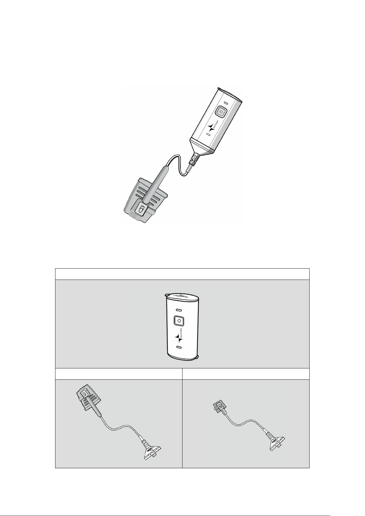
Device Components
Oximeter Box
Oximeter Sensor Cable (Adult) Oximeter Sensor Cable (Pediatric)

9
Wristband Charging Adaptor
Device Description
Oximeter Box
The Oximeter Box worn on the wrist includes a Bluetooth transmitter and a sensor
chip along with electronics for vital sign measuring and analyzing. The Oximeter Box
must be used within 32.8 feet (10 meters) spherical radius to the Display Unit (for
GA1000 Series), or to the Receiver/Transponder (for GA2000 Series).
Oximeter Sensor Cable
The Oximeter Sensor Cable is intended to be attached to the Oximeter Box on one
end and to the finger on the other end. There are two size options, adults and
pediatrics.
Wristband
The reusable wristband is intended to secure the Oximeter Box on the wrist.

10
Device Intended Use
The Oximeter Module is intended to help those who are interested in keeping watch
on oxygen saturation level (SpO2) and pulse rate (PR) of their loved ones. The device
is not intended for medical use.
Device Principle of Operation
This device measures SpO2and pulse rate based on non-invasive light-emitting diode
(LED) transmittance technology, measuring the absorbance of red and infrared light
passed through the perfused tissue during each pulse.
Device Setting Up
Before you begin your monitoring session, unpack the Oximeter Module and become
familiar with its parts. It is recommended to fully charge the Oximeter Box prior to
setting up. It takes around 3 hours to fully charge. Refer to “Device Charging” section
for detailed instructions.
Step 1: Attach the connector end of Oximeter Sensor Cable to the end marked with
SENSOR of the Oximeter Box (see figure below).
NOTE: Oximeter Sensor Cable for Adult is intended for those weighing more than 40
kilograms. Oximeter Sensor Cable for Pediatric is intended for those weighing from 10
to 40 kilograms.
CAUTION!!! Only use cables supplied or manufactured by Taiwan Aulisa Medical
Devices Technologies, Inc.

11
Step 2: Secure the Wristband onto the wrist with the Oximeter Box holder facing
outwards. Slip the velcro end through the hole and loop around to secure
the Wristband. Adjust the Wristband according to wrist size, leaving proper
space of about one or two fingers to allow ventilation.
Step 3: Insert the Oximeter Box into the holder. Attach the sensor probe to the
thumb or finger, making sure that the Oximeter Sensor Cable runs over the
top of the hand.
Step 4: Press the Power button to turn on the Oximeter Box.
CAUTION!!! Do not charge the device via this port. Charging through this port will cause
permanent damage to the device.
NOTE:
The Wristband should be worn with the arrow indicator (below figure where red
circled) facing towards the fingertips.
NOTE:
The power LED will light green when the power is ON.

12
Step 5: Set up the Display Unit.
Step 6: Set up the Receiver/Transponder (for GA2000 Series).
Step 7: Wait for the wireless connection of the system to be established. Once
connected, the vital signs and the Oximeter Module status information will
appear on the MAIN screen.
NOTE: Refer to the GA1000 Series Instructions for Use (7MN00026-01) or GA2000 Series
Instructions for Use (7MN00027-01) for setting up instructions and verifying system
operation.
NOTE: Refer to “Device Pairing” section below for more information.
NOTE: The Oximeter Module must be used within 32.8 feet (10 meters) spherical radius
to the Display Unit (for GA1000 Series), or to the Receiver/Transponder (for GA2000
Series).
NOTE: The power LED on the Oximeter Module will blink green when pairing succeeds,
and data transmission starts.

13
Device Pairing
Automatic Pairing
GA1000 Series
The Display Unit automatically detects and connects to the Oximeter Module in the
same starter kit. Press the "PAIR" button on the MAIN screen to force the system
pairing when the connection is not established automatically.
GA2000 Series
The Receiver/Transponder automatically detects and connects to the Oximeter
Module in the same starter kit only when the connection between the Display Unit
and the Receiver/Transponder has been established first.
Manual Pairing
Follow the below instructions to manually set up the pairing of a new Oximeter
Module.
Step 1: Turn on the Oximeter Module and Display Unit.
Step 2: In the Setting menu, select “PAIRING”. (for GA1000 Series)
In the Setting menu, select “PAIRING”→“SENSOR MODULE”. (for GA2000
Series)
Step 3: Scan the QR Code or key in the serial number located on the back of the
Oximeter Module.
Step 4: Press “CONFIRM” if the serial number (SN) displayed matches with the one
on the Oximeter Module.
Step 5: To confirm that the process was successful, ensure that the Bluetooth
NOTE: The Oximeter Module must be placed within 32.8 feet (10 meters) to the Display
Unit (for GA1000 Series), or to the Receiver/Transponder (for GA2000 Series).
NOTE: The Bluetooth connection status icon will turn blue once the pairing succeeds.
NOTE: The power LED on the Oximeter Module will blink green when pairing succeeds,
and data transmission starts.
NOTE: Up to four (4) Oximeter Modules can be stored on the Display Unit.

14
connection status icon on the MAIN screen of the Display Unit is lit blue.
NOTE: The Oximeter Module remains paired with the system until the serial number is
deleted from the list.
NOTE: The Oximeter Module must be placed within 32.8 feet (10 meters) to the Display
Unit (for GA1000 Series), or to the Receiver/Transponder (for GA2000 Series).
NOTE: The power LED on the Oximeter Module lights green when the power is ON.
15
Device Power Off
The oximeter module will be turned off by either way:
1. Press the Power button on the Oximeter Box.
2. When the Oximeter Module detects no signal for 3 minutes.
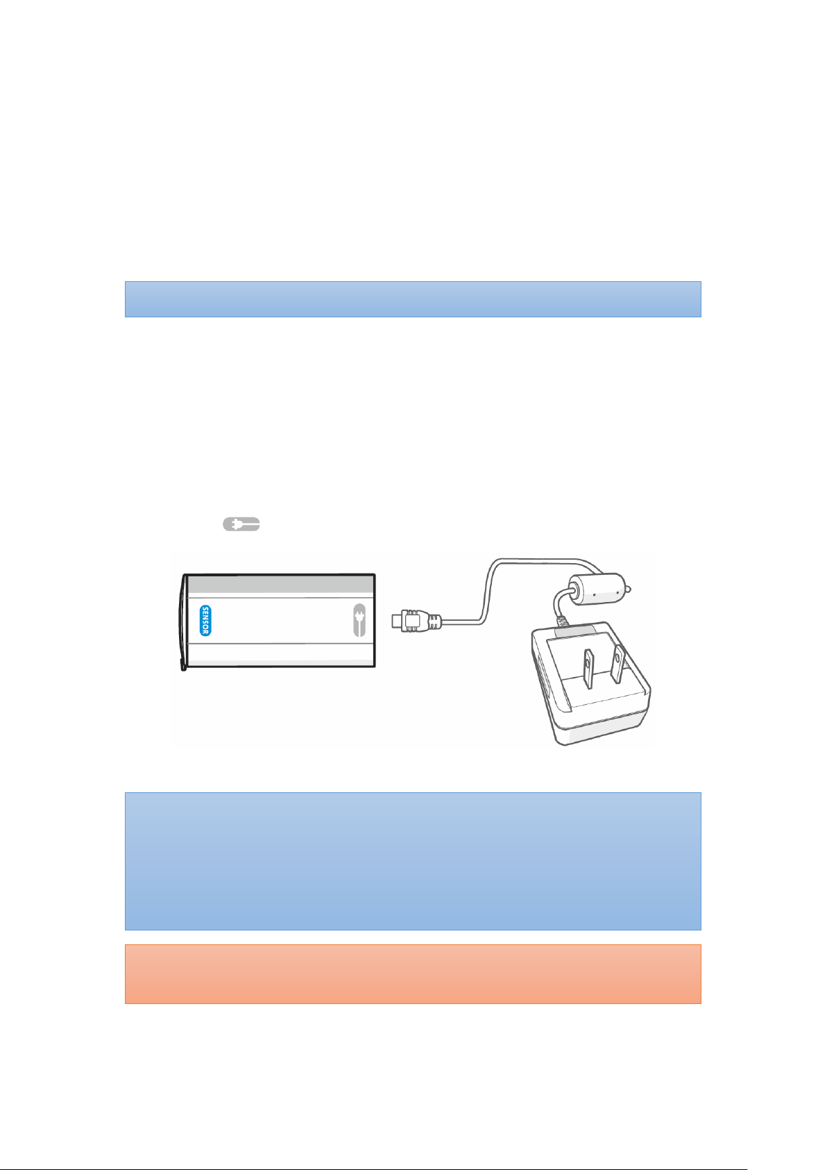
Device Charging
The Display Unit will alert the user when the Oximeter Box is on low power. Follow
the instructions below to charge the Oximeter Box.
Step 1: Plug the mini-USB end of the charging cable into the charging port marked
with on the Oximeter Box.
Step 2: Attach the wall adaptor to a power outlet.
NOTE: The power LED goes off when power off.
NOTE: The Oximeter Module works for up to extra 2 hours in the low power status.
NOTE: It takes around 3 hours to fully charge the Oximeter Box.
NOTE: The power LED indicator lights blue during charging and goes off when fully
charged.
NOTE: The Oximeter Box will power off during charging.
CAUTION!!! Only use charging adaptor supplied or manufactured by Taiwan Aulisa
Medical Devices Technologies, Inc.

16
Alarms
The Oximeter Box is equipped with an Alarm LED indicator that will blink red when a
high priority alarm occurs and blink yellow for medium priority alarm.
For more information about the alarm, refer to the GA1000 Series Instructions for
Use (7MN00026-01) or GA2000 Series Instructions for Use (7MN00027-01).
Care and Maintenance
The advanced digital circuitry within the Oximeter Module requires no calibration or
periodic maintenance. Field service or repair of this system is not possible. Do not
attempt to open the case of Oximeter Module for that will cause damage and void
the warranty. If the Oximeter Module is not functioning properly, see
“Troubleshooting” section for more information.
Cleaning and Disinfection
Clean and disinfect the Oximeter Sensor Cable before each use. First, lightly wipe the
surface of the Oximeter Sensor Cable with a soft cloth dampened with rubbing
alcohol for cleaning. Secondly, disinfect the surface of the Oximeter Sensor Cable
with a soft cloth saturated with a solution of 10% chlorine bleach in tap water. Lastly,
allow the device to dry thoroughly before reuse.
CAUTION!!! Do not pour or spray any liquids onto this device, and do not allow any
liquids to enter any openings in the device.
CAUTION!!! Do not immerse the device in liquid and do not use caustic or abrasive
cleaning agents on the device.

17
Troubleshooting
Problem Possible Solution
Cannot turn on the Oximeter
Module
1. Press the Power button again.
2. Fully charge the Oximeter Box until the LED
blue light goes off.
Unable to obtain a valid SpO2
or pulse rate reading
NOTE: In some instances,
perfusion of person being
monitored may be inadequate
for pulse detection.
1. Reposition the sensor probe or reinsert the
finger and keep the hand motionless for at
least 10 seconds.
2. Position the sensor probe at a different site.
3. Make sure the Oximeter Sensor Cable is
attached to the finger and Oximeter Box
securely.
4. Check the Oximeter Sensor Cable for any
visible signs of deterioration.
5. Warm the application site by rubbing or
covering with a blanket.
6. Allow the hand to rest comfortably without
squeezing or pressing the sensor probe on a
hard surface.
7. Make sure the Oximeter Module is within
32.8 feet (10 meters) spherical radius to the
Display Unit (for GA1000 Series), or to the
Receiver/Transponder (for GA2000 Series).
8. Reduce or eliminate any interference. Make
sure the Oximeter Module is NOT placed on
the same arm being used for other medical
therapies or diagnostics (e.g. blood
pressure cuff).
9. Check the Display Unit for any alarms or
error messages.
10. Check if the Oximeter Module is in low
power.
11. Verify the system’s wireless connection.
Unstable or constant SpO
2
and
Pulse Rate readings
1. Shield the sensor probe from any light
source.
2. Attach the sensor probe to a finger without

18
fingernail polish or an artificial nail.
3. Position the sensor probe at a different site.
4. Make sure the Oximeter Sensor Cable is
attached to the finger and Oximeter Box
securely.
5. Check the Oximeter Sensor Cable for any
visible signs of deterioration.
6. Reduce motion.
“---“ appears on the vital sign
displays
1. Make sure the Oximeter Sensor Cable is
attached to the finger and Oximeter Box
securely.
2. Position the sensor probe at a different site.
3. Make sure the Oximeter Module is within
32.8 feet (10 meters) spherical radius to the
Display Unit (for GA1000 Series), or to the
Receiver/Transponder (for GA2000 Series).
4. Verify the system’s wireless connection.
Data update period has
exceeded the limit
1. Reposition the sensor probe or reinsert the
finger and keep the hand motionless for at
least 10 seconds.
2. Position the sensor probe at a different site.
3. Attach the sensor probe to a finger without
fingernail polish or an artificial nail.
Cannot establish
system connection
1. Make sure the Oximeter Module is within
32.8 feet (10 meters) spherical radius to the
Display Unit (for GA1000 Series), or to the
Receiver/Transponder (for GA2000 Series).
2. Turn off the system and retry.
For additional troubleshooting, refer to the GA1000 Series Instructions for Use
(7MN00026-01) or GA2000 Series Instructions for Use (7MN00027-01).
If these solutions do not correct the problem, please contact your distributor, or
contact Aulisa by going online at www.aulisa.com under "Contact Us".
CAUTION!!! This system is a precision electronic instrument and must be repaired by
knowledgeable and specially trained Aulisa personnel only. Do not attempt to open the
case or repair the electronics.

19
FCC Compliance
Declaration of Conformity with FCC for Electromagnetic Compatibility
This device complies with Part 15 of the FCC Rules. Operation is subject to the
following two conditions: (1) this device may not cause harmful interference, and (2)
this device must accept any interference received, including interference that may
cause undesignated operation.
Federal Communications Commission (FCC) Notice
This equipment has been tested and found to comply with the limits for a Class B
digital device, pursuant to part 15 of the FCC Rules. These limits are designed to
provide reasonable protection against harmful interference in a residential
installation. This equipment generates, uses, and can radiate radio frequency energy.
If not installed and used in accordance with the instructions, it may cause harmful
interference to radio or television reception, which can be determined by turning the
equipment off and on. The user is encouraged to try to correct the interference by
one or more of the following measures:
(1) Reorient or relocate the receiving antenna.
(2) Increase the separation between the equipment and receiver.
(3) Connect the equipment into an outlet on a circuit different from that to which the
receiver is connected.
(4) Consult the dealer or an experienced radio/TV technician for help.
The device is designed and manufactured not to exceed the emission limits for
exposure to radio frequency (RF) energy set by the Federal Communications
Commission of the U.S. Government. These limits are part of comprehensive
guidelines and establish permitted levels of RF energy for the general population.
The guidelines are based on the safety standards previously set by both U.S. and
international standards bodies. This equipment has been shown to be capable of
compliance for localized specific absorption rate (SAR) for uncontrolled environment/
general population exposure limits specified in ANSI/IEEE Std. C95.1-1992 and has
been tested in accordance with the measurement procedures specified in IEEE Std.
1528-200X (Draft 6.5, January 2002).
FCC Radiation Exposure Statement
For body worn operation, to maintain compliance with FCC RF exposure guidelines,
use only accessories that contain nonmetallic components. RF exposure separation
distance is 5 mm. Use of other accessories may violate FCC RF exposure guidelines
Other manuals for Guardian Angel GA1000 Series
2
This manual suits for next models
6
Table of contents
Popular Oxygen Equipment manuals by other brands

Precision Medical
Precision Medical PM5900 user manual

ResMed
ResMed ULTRAMIRAGE 608140/20611 Clinical Guide

Nidek Medical
Nidek Medical Mark 5 Nuvo Series Instructions for use

C-Aire
C-Aire HI Flow operating instructions

WARDRAY PREMISE
WARDRAY PREMISE SafeAir Room Oxygen Monitor Operator's manual

Inogen
Inogen One G4 Technical manual


