WARDRAY PREMISE SafeAir Room Oxygen Monitor User manual

GEN.S.20/296April 2020
MR105D
MRI Room Oxygen Monitor - SafeAir®
OPERATORS MANUAL

2
Index
Page 2MR ASTM Safety Definitions
Page 3Introduction
Page 4General Information
Page 5Contents included
Page 6System Description
Page 7Oxygen Monitor Parts Reference
Page 8System Installation
Page 9Diagram for installation
Page 10 Power Up Guide
Page 11 Power Down Guide
Page 12 –13 Maintenance
Page 14 Servicing & Cleaning
Page 15 Warranty
Safety Definitions for MRI as Defined by International Standard
F2503-20
MR SAFE:
An item that poses no known hazards resulting from exposure to any MR
environment. MR SAFE items are composed of materials that are electrically
non-conductive, non-metallic, and non-magnetic.
MR CONDITIONAL:
An item with demonstrated safety in the MR environment within defined
conditions including conditions for the static magnetic field, the time-varying
gradient magnetic fields and the radiofrequency fields.
Supplementary marking – additional information that, in association with
marking as “MR CONDITIONAL,” states via additional language the conditions in
which an item can be used safely within the MR environment.
MR UNSAFE:
An item which poses unacceptable risks to the patient, medical staff or other
persons within the MR environment.

3
Introduction
Thank you for purchasing the MR105D SafeAir® Room Oxygen Monitor. This product is
manufactured and tested to the highest standards.
The unit also complies with the following standards:
EMC Directive 2014/30/EU;
Low Voltage Directive 2014/35/EU; and
RoHS Directive 2011/65/EU
Important note: The Oxygen Monitor unit is MR Unsafe and must not be taken into the MR
room.
To ensure that you obtain maximum benefit from your product, please take a few minutes to read
the enclosed information regarding operation, service and maintenance.
If you have any problems in the meantime or would like any advice about this or any other MR
products from the Wardray Premise range, please contact us at our Head Office:
Wardray Premise Limited, Hampton Court Estate, Summer Road
Thames Ditton, Surrey, KT7 0SP, UK
Tel: +44 (0) 20 8398 9911
Fax: +44 (0) 20 8398 8032
E-mail: sales@wardray-premise.com
Kindly note:
If you modify a Wardray Premise product you will invalidate your warranty.
Unless you have our express written permission to modify a product, we transfer all liabilities for
modified products to you.
EU Authorised Representative:
Advena Ltd
Tower Business Centre
2nd Floor, Tower Street
Swatar
BKR 4013
Malta

4
Room Ventilation Interface - Emergency Extract Connector
The Oxygen Monitor is fitted with a pair of contacts to enable the MRI room ventilation system to
be activated due to a low oxygen level - (The alarm will sound on the monitor). The contacts are
accessed via the four pin socket mounted on the rear of the unit, pin numbers are as follows:-
PIN 1 = Normally open contact
PIN 2 = Not Used.
PIN 3 = Normally open contact
PIN 4 = EARTH CONNECTION TO CASE
The switching contacts are rated at 230V AC 3A MAX / 115V AC 6A MAX.
General Information
The SafeAir® Oxygen Monitor has been designed to give a warning of depleted oxygen levels in
the scan room.
The unit is simple to fit either during the installation of the scanner, or retro fitted into existing MRI
rooms afterwards, and does not require the scanner to be ramped down. It can be linked into an
extraction system to allow automatic switch on if oxygen levels drop.
The normal oxygen concentration should be 21%. Any variation will be rapidly detected.
The system may only be installed by operators with sufficient knowledge of equipment and this
operators manual.
Unit height
mm
360
Unit width
mm
120
(max)
Unit depth
mm
230
(inc. cable)
Unit weight
Kg
4.5
Unit Usage
Powered by: Power Pax A/C adapter Model No: ATS065T-P180
Power Requirements:
Input: 100-240V A/C 50/60Hz 1.4A Max
Output: 18V DC 3.62A
Suitable for use in all markets.

5
Contents included
SafeAir® Oxygen Monitor unit1
230V AC - 18 V DC Transformer - Part No: MR40-LR2
2 pin European / continental socket plug3
3 pin UK socket plug4
30m Flexible PVC hose5
Vent Relay / Emergency Extract Connector6
Envitec - Instructions for use and PC software CD7
8Envitec - Short manual leaflet
123
45
6
78

6
System Description
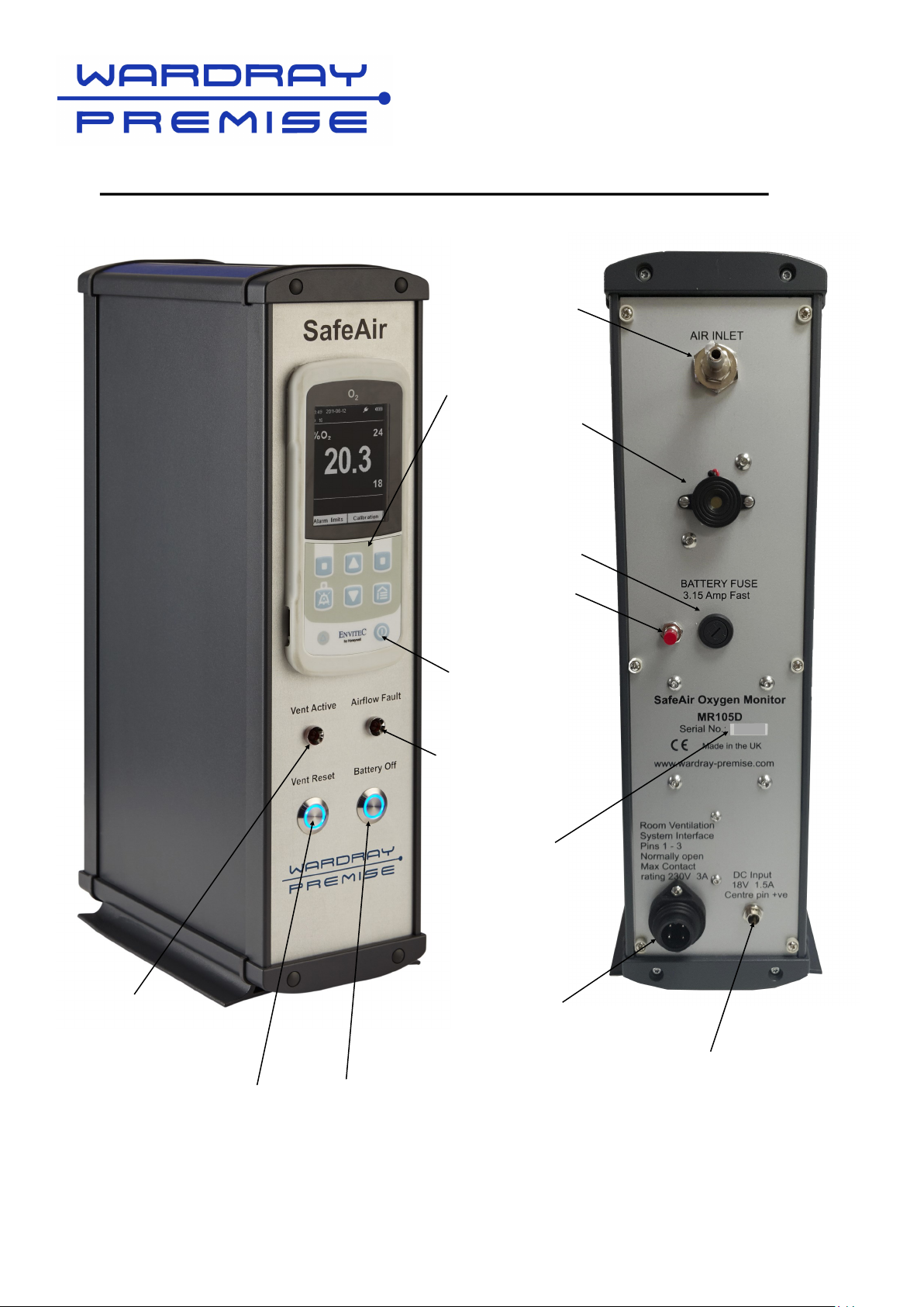
The SafeAir® unit comprises an Envitec O2 oxygen monitor system supported by an air sampling
pump, HEPA air filter, pressure switch, alarm buzzer and associated airlines.
The unit has an internal ‘dryfit’ battery which powers the external alarm and vent relay circuits in
the event of mains power loss. In normal operation the system is powered by an external 18v DC
desktop power supply.
In operation, air is drawn through a 6mm PVC flexible hose via a user replaceable HEPA filter,
past the sensor in the Blue T piece housing and via the sampling pump (See page 13), it exits via
a pressure switch and exhaust valve combination.
If the pressure switch detects a drop in pressure the system will activate an alarm buzzer, located
on the rear of the unit, and illuminate the ‘Airflow Fault’ light on the front.
This can happen if the air sampling pipe becomes blocked or kinked or, after an extended
operational time, the HEPA filter reduces airflow and needs replacing. (See page 12)
In this condition the O2 sensor will not sense enough oxygen and the Envitec unit will also alarm
until the airflow is restored and the O2 is back to its normal levels.
The Envitec alarm will cause the ‘% oxygen’ display to turn red, the ‘Vent Active’ light on the front
will illuminate and the vent relay will operate.
If the unit has been connected to an external magnet room venting system (Emergency Extract)
then this will be active whilst the alarm condition exists.
The alarms and LED indicators are intended to get the attention of operations staff and for them
to remedy the problem.
Important Note: Should the operator decide to unplug the unit at the mains, in an attempt to
silence the alarm, the alarm (now powered by the internal ‘dryfit’ battery) will continue to sound
until the battery finally runs down (several hours). For correct procedure to preserve batteries
See page 11 for Power Down guide.

7
‘Envitec’
Power On/Off
button
18V DC Power supply in
Alarm buzzer
Air inlet
MR105D SafeAir® Room Oxygen Monitor parts reference
Airflow Fault light
Vent Active light
Vent Reset Battery off
‘Envitec’
O2 Oxygen
Monitor
Serial No.
Reset button
Fuse
Emergency
Extract
Connector

8
System Installation
Please note: This unit is specifically designed to monitor oxygen levels within the MRI
Scanner room safely from within the control room.
Unpack the items and check against the packing list.
1. Position the Oxygen monitor in a suitable location in the MRI Control Room to allow the end
user to be able to see the LCD screen and, under fault conditions, hear the audible alarm.
2. If not already fitted remove the back of the unit by undoing the six Philips screws and fit the
Sensor Cell and HEPA Vent Filter (See Page 12). Replace the back.
3. The power supply unit is plugged into the DC input socket (on the back of the unit Fig 1) and
the mains plug inserted in a suitably positioned wall socket.
4. Connect the PVC flexible hose to the chromed ‘Air Inlet’ nozzle on the back of the unit (Fig 2).
5. The other end of the flexible hose should be routed through a suitable open wave guide into
the MR Scan room, allowing the hose to be routed to the close proximity of the cold head of
the MRI scanner. This is usually within the suspended ceiling cavity and secured in place
along the run with cable ties. Any excess tubing should be cut off.
(see Drawing 1420C on page 9)
The unit can now be switched on at the mains.
Please see page 10 of the Manual for final power up guidance.
Fig1 Fig 2
The unit is also supplied with a vent relay/emergency extract connector
plug to allow an emergency extractor fan to be connected.
The emergency extractor fan, if required, is supplied by others and final
connection made by others.

9
Drawing 1420C

10
Power Up Guide
For the first time, or after an extended period of being disconnected from the main supply, the
unit should be left powered on whilst the internal ‘dryfit’ battery and Envitec batteries are charged
up - ideally overnight. However, we recommend that the unit is left on permanently.
The Envitec screen will display an animated battery charging symbol (See Fig 1).
Once charged the animated battery symbol will become static and the Envitec unit can be
switched on (Press On button - See Page 11 opposite: Fig 3).
The Envitec unit will go through a self-test procedure which includes activating the alarm. This
self-test will activate the vent relay and also the ‘Vent Active’ light on the front.
As the self-test procedure finishes the Envitec alarm condition will clear but the ‘Vent Active’ LED
will remain lit. The user must clear the condition by pressing the ‘Vent Reset’ switch on the
front of the unit below the Vent Active LED (see Page 11 opposite: Fig 4).
On newly installed systems or systems where the O2 sensor has been replaced (see Page 12 for
instructions), the Envitec unit will generally need to be recalibrated.
This can be done with a 100% O2 source or more commonly with the current ambient levels of
O2 assumed to be acceptable.
The default screen of the Envitec unit includes ‘Alarm Limits’ and ‘Calibration’ legends. Press the
relevant function key, below the screen, depending on the application (see Fig 2).
Use the Calibration function to calibrate the unit: Ambient Air - 21%; Pure Oxygen - 100%.
Use the alarm limits button to set the %O2 upper and lower limits outside of which the system
should alarm.
Caution! Danger! The oxygen concentration of the breathing air supply must not be lower than
18%
These procedures are described in the Envitec user manual supplied with the system on a CD.
We recommend printing the manual for future reference.
Fig 1 Fig 2

11
Power Down Guide
The system can be left running 24/7.
If the user requires the system to be powered down, either due to an alarm condition or power
saving over a long weekend when O2 monitoring is not required, then a shutdown procedure
must be followed to avoid flattening the internal batteries.
The correct procedure is:
1. Turn off the Envitec unit first using the on/off button* (See Fig 3).
*Turning off the Envitec unit involves holding the on/off button whilst the display shows a
countdown of 3, 2, 1 then release button promptly.
2. Then unplug from the mains and press the battery on/off button again* (this will silence the
alarm).
Important note:
Failure to turn off the Envitec unit whilst the SafeAir unit is unplugged will cause the Envitec
internal battery to go flat. This may cause the display to lock up with an invalid O2 level
displayed.
If the unit has been powered down incorrectly (not following the steps above), and the batteries
have been allowed to go flat, then to recover the situation there is a reset switch (red button) on
the rear of the unit (See Fig 4).
With the unit still unplugged press the reset switch for 5 seconds, release and then follow the
‘Power up guide’.
The reset switch disconnects the Envitec battery momentarily.
Fig 4
Fig 3

12
Maintenance
Installation and Replacement Procedure For The Oxygen Fuel Cell
and HEPA Vent Filter
Before attempting any maintenance to the oxygen monitor system, disconnect the mains
supply and switch off oxygen monitor. (See Power down guide on Page 11)
It is recommended that both the oxygen fuel cell and air line filter are replaced together. This is
available as a kit from Wardray Premise Ltd. (Ref: MR106).
• Undo the six screws securing the back
Oxygen Fuel Cell—see image on page 13
• Remove the fuel cell cable from the bottom of the fuel cell by pulling upwards.
• Gently ease the fuel cell out of the retaining body (blue section). Unscrew the bottom part
of the fuel cell (see Fig 1)
• Screw the replacement oxygen sensor into the fuel cell connector, being careful not to over
tighten and reinstall into the blue section, attach the fuel cell cable connector.
HEPA Vent Filter—see image on page 13
• Gently pull the air lines to disconnect from both ends of the air filter. Replace the filter and
reconnect both inlet and outlet air lines, making sure that the inlet side of the filter faces the
inlet nozzle (Side with the writing on—see Fig 2). Ensure that the air lines are securely
connected.
• Re-fit the back case with the six screws.
• Check the operation and calibration of the oxygen monitor by switching on the pump,
battery and monitor (See Power up guide on Page 10). In normal air the display will read
21% oxygen content.
Important
It is recommended that the filter and fuel cell sensor are replaced every 6 months.
The replacement kit (Ref: MR106) may be obtained directly from Wardray Premise Ltd or in
overseas countries from our local agents.
When switched on the fuel cell cable plug has a voltage on its terminals (to power the fuel cell),
which must not be allowed to touch the chassis if left disconnected. If the unit is shipped without
the fuel cell fitted, the plug will have a cover fitted to prevent contact with the chassis if the unit is
inadvertently switched on. Please ensure that the contacts of this connector are not allowed to
touch any part of the chassis during the fitting of a fuel cell.

13
Medical Oxygen Sensor Fuel Cell
Fuel Cell cable connector
Ease out gently here
Fig 1
HEPA Vent Filter
Fig 2
O2 Sensor ‘T’ Piece Housing

14
Servicing
The system may only be serviced by authorised personnel. The system automatically tests all of
its functions every time it is switched on and will show any faults it detects. The system also
continuously monitors all of its functions while operating.
Always check the unit and cables for external damage before use.
Cleaning
Cleaning is limited to wiping down the control unit with a clean dry cloth for the removal of dust /
debris.
The unit may only be disinfected by wiping it gently with a soft, disposable cloth soaked in
isopropyl alcohol.
Do not allow any moisture to enter the device.
Warranty
The SafeAir Oxygen Monitor comes with a 12 months warranty against defective components or
faulty workmanship.
Please register your product with us, via the Warranty Registration Form (see page 15), for ease
of contact in case of urgent upgrades or recalls.
If the unit is damaged please do not attempt to repair as this could invalidate your warranty and
could compromise its safety, please call or email Wardray Premise Limited:
T: +44 (0) 20 8398 9911
F: +44 (0) 20 8398 8032
E-MAIL: sales@wardray-premise.com
Please include the product code and the product’s serial number when contacting
Wardray Premise.

15
This manual suits for next models
1
Table of contents