AUMA LE Series User manual
Linear thrust unit
LE 12.1 –LE 200.1
Assembly, operation, commissioningOperation instructions

Read operation instructions first.
●Observe safety instructions.
●These operation instructions are part of the product.
●Retain operation instructions during product life.
●Pass on instructions to any subsequent user or owner of the product.
Purpose of the document:
This document contains information for installation, commissioning, operation and maintenance staff.It is intended
to support device installation and commissioning.
Table of contents Page
41. Safety instructions................................................................................................................. 41.1. Basic information on safety 41.2. Range of application 51.3. Warnings and notes 51.4. References and symbols
62. Identification........................................................................................................................... 62.1. Name plate 72.2. Short description
83. Transport, storage and packaging........................................................................................ 83.1. Transport 93.2. Storage 93.3. Packaging
104. Assembly................................................................................................................................ 104.1. Mounting position 104.2. Actuators for linear thrust units 114.3. Mounting the linear thrust unit to a valve 114.3.1. Attachment dimensions for mounting to valve 124.3.2. Linear thrust unit: mount to valve
135. Commissioning...................................................................................................................... 135.1. Stroke 135.2. Thrust limitation 145.3. Test run
156. Servicing and maintenance................................................................................................... 156.1. Preventive measures for servicing and safe operation 156.2. Maintenance intervals 166.3. Re-lubrication 166.4. Disposal and recycling
177. Technical data......................................................................................................................... 177.1. Features and functions 187.2. Service conditions 187.3. Further information
198. Spare parts............................................................................................................................. 198.1. Linear thrust unit LE 12.1 –LE 200.1 218.2. Linear thrust units LE 12.1 —LE 200.1 with base
2
LE 12.1 –LE 200.1
Table of contents

239. Certificates.............................................................................................................................. 239.1. EU Declaration of Conformity / Declaration of Incorporation
24Index........................................................................................................................................
25Addresses...............................................................................................................................
3
LE 12.1 –LE 200.1 Table of contents

1. Safety instructions
1.1. Basic information on safety
Standards/directives Our products are designed and manufactured in compliance with recognised
standards and directives.This is certified in a Declaration of Incorporation and an
EU Declaration of Conformity.
The end user or the contractor must ensure that all legal requirements, directives,
guidelines, national regulations and recommendations with respect to assembly,
electrical connection, commissioning and operation are met at the place of installation.
Safetyinstructions/warn-
ings All personnel working with this device must be familiar with the safety and warning
instructions in this manual and observe the instructions given. Safety instructions
and warning signs on the device must be observed to avoid personal injury or property
damage.
Qualification of staff Assembly, electrical connection, commissioning, operation, and maintenance must
be carried out exclusively by suitably qualified personnel having been authorised by
the end user or contractor of the plant only.
Prior to working on this product, the staff must have thoroughly read and understood
these instructions and, furthermore, know and observe officially recognised rules
regarding occupational health and safety.
Work performed in potentially explosive atmospheres is subject to special regulations
which have to be observed.The end user or contractor of the plant are responsible
for respect and control of these regulations, standards, and laws.
Commissioning Prior to commissioning, it is important to check that all settings meet the requirements
of the application. Incorrect settings might present a danger to the application, e.g.
cause damage to the valve or the installation.The manufacturer will not be held
liable for any consequential damage.Such risk lies entirely with the user.
Operation Prerequisites for safe and smooth operation:
●Correct transport, proper storage, mounting and installation, as well as careful
commissioning.
●Only operate the device if it is in perfect condition while observing these instruc-
tions.
●Immediately report any faults and damage and allow for corrective measures.
●Observe recognised rules for occupational health and safety.
●Observe the national regulations.
●During operation,thedevice warmsupandincreasedsurfacetemperature may
occur.To prevent possible burns, we recommend checking the surface temper-
ature using an appropriate thermometer and wearing protective gloves, if re-
quired, prior to working on the device.
Protective measures The end user or the contractor are responsible for implementing required protective
measures on site, such as enclosures, barriers, or personal protective equipment
for the staff.
Maintenance To ensure safe device operation, the maintenance instructions included in this manual
must be observed.
Any device modification requires prior written consent of the manufacturer.
1.2. Range of application
AUMA linear thrust units are designed for the operation of industrial valves, e.g.
globe valves.
Other applications require explicit (written) confirmation by the manufacturer.
The following applications are not permitted, e.g.:
●Industrial trucks according to EN ISO 3691
4
LE 12.1 –LE 200.1
Safety instructions
●Lifting appliances according to EN 14502
●Passenger lifts according to DIN 15306 and 15309
●Service lifts according to EN 81-1/A1
●Escalators
●Continuous duty
●Radiation exposed areas in nuclear power plants
No liability can be assumed for inappropriate or unintended use.
Observance of these operation instructions is considered as part of the device's
designated use.
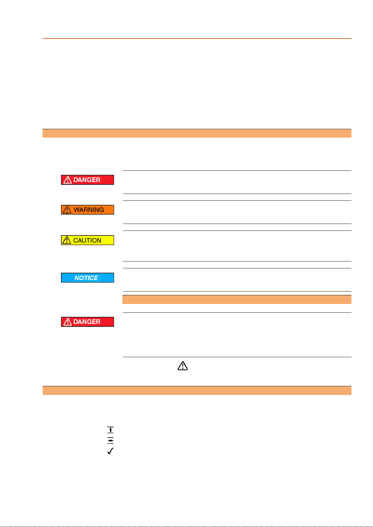
1.3. Warnings and notes
The following warnings draw special attention to safety-relevant procedures in these
operation instructions, each marked by the appropriate signal word (DANGER,
WARNING, CAUTION, NOTICE).
Indicates an imminently hazardous situation with a high level of risk. Failure
to observe this warning could result in death or serious injury.
Indicates a potentially hazardous situation with a medium level of risk. Failure
to observe this warning could result in death or serious injury.
Indicates a potentially hazardous situation with a low level of risk. Failure to
observe this warning could result in minor or moderate injury. May also be
used with property damage.
Potentially hazardous situation. Failure to observe this warning could result
in property damage. Is not used for personal injury.
Arrangement and typographic structure of the warnings
Type of hazard and respective source!
Potential consequence(s) in case of non-observance (option)
→Measures to avoid the danger
→Further measure(s)
Safety alert symbol warns of a potential personal injury hazard.
The signal word (here: DANGER) indicates the level of hazard.
1.4. References and symbols
The following references and symbols are used in these instructions:
Information The term Information preceding the text indicates important notes and information.
Symbol for CLOSED (valve closed)
Symbol for OPEN (valve open)
Important information before the next step.This symbol indicates what is required
for the next step or what has to be prepared or observed.
< > Reference to other sections
Terms in brackets shown above refer to other sections of the document which provide
further information on this topic.These terms are either listed in the index, a heading
or in the table of contents and may easily be located.
5
LE 12.1 –LE 200.1 Safety instructions
2. Identification
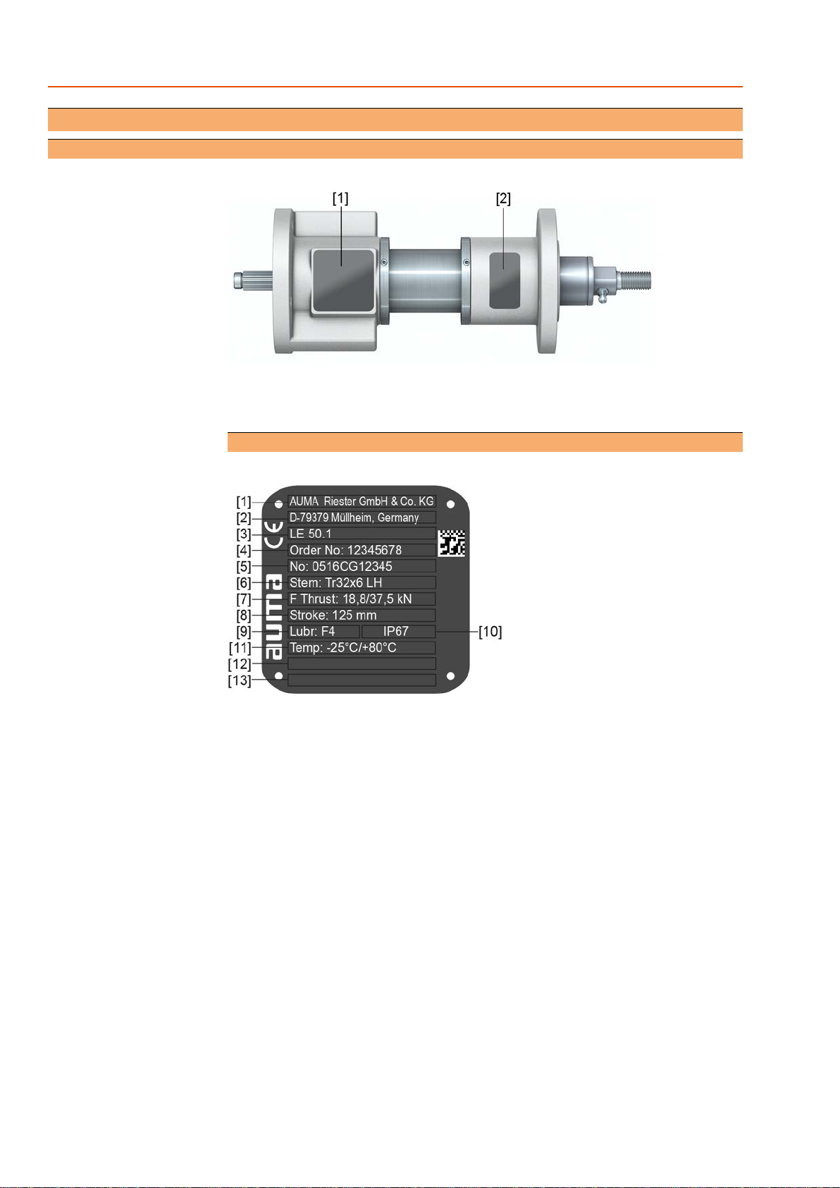
2.1. Name plate
Figure 1: Arrangement of name plates
[1] Linear thrust unit name plate
[2] Additional plate, e.g.KKS (Power Plant Classification System) plate or approval
plate
Description of linear thrust unit name plate
Figure 2: Linear thrust unit name plate (example)
[1] Name of manufacturer
[2] Address of manufacturer
[3] Type and size (see explanation below)
[4] Order number (see explanation below)
[5] Serial number (works number)
[6] Stem (see explanation below)
[7] Thrust (for modulating duty/open-close duty)
[8] Stroke
[9] Lubricant
[10] Enclosure protection
[11] Ambient temperature
[12] Explosion-proof version (option)
[13] Customer information (option)
Type and size These instructions apply to the following device types and sizes:
Linear thrust unit: LE 12.1 –LE 200.1
Stem Thread diameter, flank lead and version of stem.
●LH = Stem extension for clockwise rotation, i.e.multi-turn actuator closes the
valve in a clockwise rotation
6
LE 12.1 –LE 200.1
Identification

●RH = Stem retraction for clockwise rotation, i.e.multi-turn actuator closes the
valve in a counterclockwise rotation
Order number The product can be identified using this number and the technical data as well as
order-related data pertaining to the device can be requested.
Please always state this number for any product inquiries.
On the Internet at http://www.auma.com > Service & Support > myAUMA, we offer
a service allowing authorised users to download order-related documents such as
wiring diagramsand technical data (both in German and English), inspection certificate
and the operation instructions when entering the order number.
Description of approval plate in explosion-proof version (option)
Figure 3: Approval plate in explosion-proof version (example)
[1] Ex symbol, CE mark, number of test authority
Classification:
[2] Gas explosion protection
[3] Dust explosion protection
2.2. Short description
AUMA linear thrust units type LE 12.1 –LE 200.1 are designed for the operation of
industrial valves, e.g.globe valves.
Theyare usedincombinationwith multi-turn actuatorsonvalveswhichrequirelinear
travel.The linear thrust units convert the output torque of the multi-turn actuator into
an axial thrust.As an option, AUMA linear thrust units are available with spring-loaded
damping devices to compensate for changes in lengths caused by varying
temperatures, for example.
7
LE 12.1 –LE 200.1 Identification
3. Transport, storage and packaging
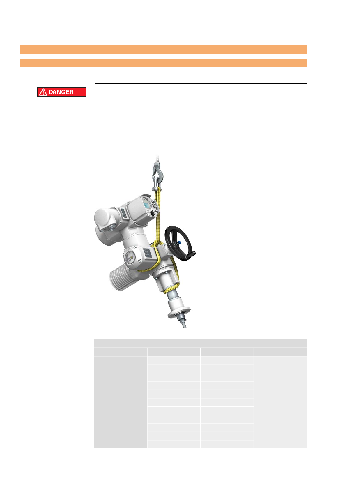
3.1. Transport
For transport to place of installation, use sturdy packaging.
Hovering load!
Death or serious injury possible.
→Do NOT stand below hovering load.
→Linear thrust units mounted to a valve in combination with an actuator: Attach
ropes or hooks for the purpose of lifting by hoist to valve and NOT to actuator.
→Respect total weight of combination (gearbox, linear thrust unit, actuator, ...).
Figure 4: Example: Lifting the linear thrust
Table 1:
Weights linear thrust units
Base weight [kg]Weight [kg]2)
Stroke1)
Type1)
11850LE 12.1/ LE 25.1
9100
9125
10200
11250
13400
14500
111063LE 50.1
12125
15250
18400
8
LE 12.1 –LE 200.1
Transport, storage and packaging

Weights linear thrust units
Base weight [kg]Weight [kg]2)
Stroke1)
Type1)
402380LE 70.1 / LE 100.1
26160
32320
35400
4045100LE 200.1
50200
62400
68500
Refer to name plate1) Without actuator and base2)
3.2. Storage
Danger of corrosion due to inappropriate storage!
→Store in a well-ventilated, dry room (maximum humidity 70 %).
→Protect against floor dampness by storage on a shelf or on a wooden pallet.
→Cover to protect against dust and dirt.
→Apply suitable corrosion protection agent to uncoated surfaces.
Long-term storage For long-term storage (more than 6 months), observe the following points:
1. Prior to storage:
Protect uncoated surfaces, in particular the output drive parts and mounting
surface, with long-term corrosion protection agent.
2. At an interval of approx. 6 months:
Check for corrosion.If first signs of corrosion show, apply new corrosion protec-
tion.
3.3. Packaging
Our products are protected by special packaging for transport when leaving the
factory.The packaging consists of environmentally friendly materials which can easily
be separated and recycled.We use the following packaging materials: wood,
cardboard, paper, and PE foil. For the disposal of the packaging material, we
recommend recycling and collection centres.
9
LE 12.1 –LE 200.1 Transport, storage and packaging
4. Assembly
4.1. Mounting position
The linear thrust units described here can be operated without restriction in any
mounting position.
4.2. Actuators for linear thrust units
Assembly is performed in compliance with actuator operation instructions.This
section provides information and indications regarding suitable actuators, flanges,
and screws.
State of delivery When AUMA actuators and linear thrust units up to size LE 50.1 and a stroke of max.
200 mm are supplied together, assembly is performed in the factory. For larger
strokes and when exceeding size LE 70.1, assembly must be performed by the
customer.The suitable output drive sleeve and the screws for assembly are generally
part of the scope of delivery.
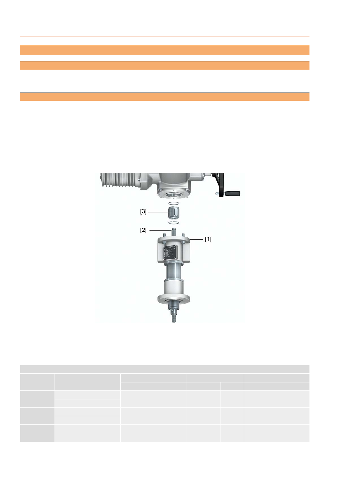
Figure 5: Example of AUMA multi-turn actuator with LE 25.1
[1] Actuator mounting flange
[2] Stem
[3] Output drive sleeve with retaining ring
Table 2:
Suitable AUMA actuators, flanges, and screws
Tightening torque TA[Nm]ScrewsActuator mounting flangeSuitable AUMA actuatorType
Strength class A2-70QuantitySizeEN ISO 5210
364M10 x 30F10, F10-ZB1)
SA 07.2/SAR 07.2LE 12.1
SVC 05.1/SVCR 05.1
364M10 x 30F10, F10-ZB1)
SA 07.6/SAR 07.6LE 25.1
SVC 07.1/SVCR 07.1
364M10 x 30F10, F10-ZB1)
SA 10.2/SAR 10.2LE 50.1
SVC 07.5/SVCR 07.5
10
LE 12.1 –LE 200.1
Assembly
Suitable AUMA actuators, flanges, and screws
Tightening torque TA[Nm]ScrewsActuator mounting flangeSuitable AUMA actuatorType
Strength class A2-70QuantitySizeEN ISO 5210
1504M16 x 40F14, F14-ZB1)
SA 14.2/SAR 14.2LE 70.1
1504M16 x 40F14, F14-ZB1)
SA 14.6/SAR 14.6LE 100.1
2944M20 x 50F16, F16-ZB1), F252)
SA 16.2/SAR 16.2LE 200.1
Actuator mounting flange with 2 holes for pivots1) Extension flange F16/25 max. input torque 1,000 Nm2)
4.3. Mounting the linear thrust unit to a valve
Mounting position Mounting is most easily done with the valve shaft pointing vertically upward. But
mounting is also possible in any other position.
Linear thrust units leave the factory with retracted stem.
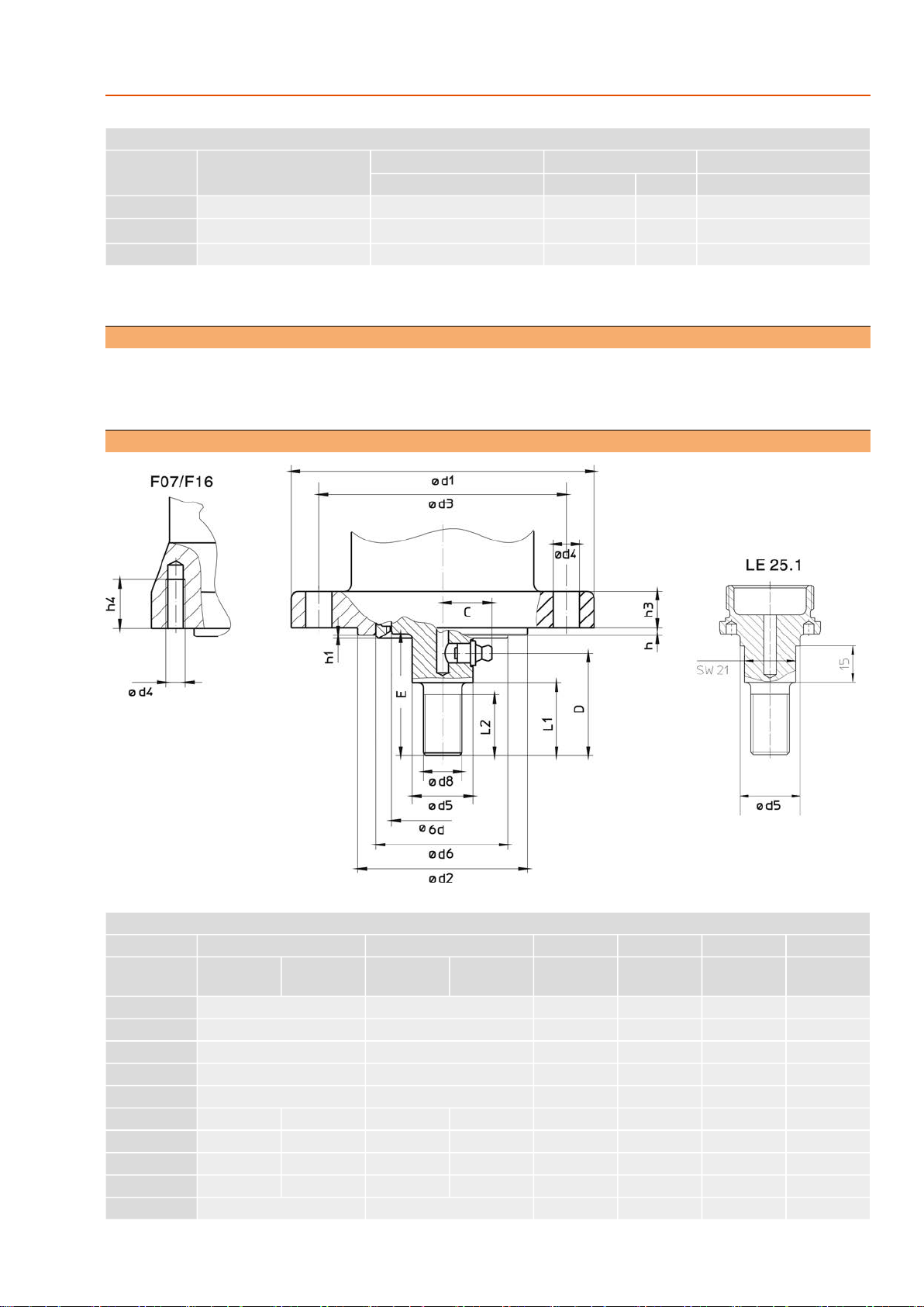
4.3.1. Attachment dimensions for mounting to valve
Table 3:
Attachment dimensions to valve
LE 200.1LE 100.1LE 70.1LE 50.1LE 25.1LE 12.1Dimensions
F16
(G3)
F14
(G1/2)
F14
(G1/2)
F10
(–)
F10
(G0)
F07
(G0)
F10
(G0)
F07
(G0)
EN ISO 5210
(DIN 3210)
292626242118C
766363434237D
907575555045E ±0.2
–––353025L1
655555302520L2
210175175125⎕125⎕75⎕125⎕75∅d1
130 f8100 f8100 f870 g770 f8(55 g7 = d6)70 f8(55 g7 = d6)∅d2
1651401401021027010270∅d3
M2018181111M811M8∅d4 (4x)
423636322520∅d5
11
LE 12.1 –LE 200.1 Assembly

Attachment dimensions to valve
LE 200.1LE 100.1LE 70.1LE 50.1LE 25.1LE 12.1Dimensions
F16
(G3)
F14
(G1/2)
F14
(G1/2)
F10
(–)
F10
(G0)
F07
(G0)
F10
(G0)
F07
(G0)
EN ISO 5210
(DIN 3210)
120–––551)
–551)
–∅d6 g7
M42 x 3M36 x 3M36 x 3M20 x 1.5M16 x 1.5M12 x 1.25∅d8
1007070554242∅d9 –0.1
4443.433.433.4h
0.5–––0.5–0.5–h1
–18181515–15–h3
32––––20–20h4
Grease nipple A-D8 according to DIN 71412
Spigot for F071)
4.3.2. Linear thrust unit: mount to valve
1. Check whether attachment dimensions of linear thrust unit suit the valve.
2. Push stem of linear thrust unit to desired position (e.g.OPEN) using the hand-
wheel.
➥Mount valve and actuator in the same end position.
➥For globe valves, the conventional assembly position is end position CLOSED
(stem is retracted).
3. Clean mounting surfaces (mounting flanges at linear thrust unit and valve).
Thoroughly degrease uncoated mounting surfaces.
4. Place linear thrust unit onto valve as to ensure that bores or thread align with
the output mounting flanges.
Information: Ensure that the spigot fits uniformly in the recess and that the
mounting faces are in complete contact.
5. Fasten linear thrust unit with screws according to table.
Information: We recommend applying liquid thread sealing material to the
screws to avoid contact corrosion.
6. Fasten screws crosswise to a torque according to table.
Table 4:
Tightening torques for screws
Tightening torque [Nm]Threads
Strength class
A2-80/A4-80A2-70/A4-70
107.4M6
2418M8
4836M10
8261M12
200150M16
392294M20
7. Connect coupling stud (∅d8) of linear thrust unit with valve stem.
Information: The type of connection depends on the valve and is determined
by the valve manufacturer.
8. In case of risk of jamming due to moving parts: Provide protective equipment.
12
LE 12.1 –LE 200.1
Assembly
5. Commissioning
5.1. Stroke
The stroke of linear thrust units is limited by end stops.
Damage at linear thrust unit due to excessive torques!
→Max. permissible input speeds may not be exceeded.
Approaching the end stops in motor operation!
Risk of damage at linear thrust unit.
→DO NOT use end stops as stroke limitation in motor operation.
→Prior to performing motor operation: Limit stroke via limit switching in multi-turn
actuator (setting).
→Observe overrun when performing the setting.
Stroke setting The stroke per turn depends on the thread pitch of the stem (refer to name plate).
The setting of end positions OPEN and CLOSED within the possible stroke of the
linear thrust unit is done via the mounted multi-turn actuator.Refer to <Limit switching:
set> chapter in operation instructions of suitable AUMA multi-turn actuators.
5.2. Thrust limitation
Thrust limitation is made via mounted actuator.
Refer to <Limit switching: set> chapter in operation instructions of suitable AUMA
multi-turn actuators.
Damage at linear thrust unit due to excessive torque!
→Max. permissible thrusts may not be exceeded.
→Use actuator in recommended size.
→Stall torque operations and operations while bypassing the torque switches are
not permitted.
Valve damage due to excessive tripping torque limit setting!
→The tripping torque must suit the valve.
→Only change the setting with the consent of the valve manufacturer.
Calculation of thrust limitation (tripping torque)
The maximum required or permissible thrust [F in kN) for a globe valve must be
converted to torque [T in Nm] when setting the actuator torque switching:
Formula: T = F x f
LE 200.1LE 100.1LE 70.1LE 50.1LE 25.1LE 12.1Type 4.63.93.93.22.62.6Factor f
The thrust limitation is then performed indirectly using the calculated value through
the setting of the torque switching at the mounted multi-turn actuator.
Example:
Max. permissible thrust of globe valve:F = 30 kN
Linear thrust unit type LE 50.1 (factor f = 3.2)
T = 30 kN x 3.2 m/k = 96 Nm
Multi-turn actuator type SA 10.2; torque range 40 –120 Nm
13
LE 12.1 –LE 200.1 Commissioning

5.3. Test run
Moving parts!
Danger of jamming.
→Keep hands clear from stroke range of combination.
→If necessary, fit protection cover.
Verify stroke direction Information:AUMA linear thrust units type LE 12.1 –LE 200.1 leave the factory
with retracted stem (end position OPEN).
1. Move actuator manually to intermediate position or to sufficient distance from
end position.
2. Switch on actuator in direction OPEN and observe the direction of stroke.
→Switch off before reaching the end position.
3. In case of incorrect direction of stroke, reverse rotary direction at actuator.
4. Then: Approach end position CLOSED and end position OPEN and check
seating.
14
LE 12.1 –LE 200.1
Commissioning

6. Servicing and maintenance
Damage caused by inappropriate maintenance!
→Servicing and maintenance must be carried out exclusively by suitably qualified
personnel having been authorised by the end user or the contractor of the plant.
Therefore, we recommend contacting our service.
→Only perform servicing and maintenance tasks when the device is switched off.
AUMA
Service & Support AUMA offers extensive service such as servicing and maintenance as well as
customer product training.For the relevant contact addresses, please refer to
<Addresses> in this document or to the Internet (www.auma.com)
6.1. Preventive measures for servicing and safe operation
The following actions are required to ensure safe device operation:
Every 6 months after commissioning and then once a year
●Perform visual inspection for grease leakage.
●Check fastening screws between actuator, linear thrust unit and valve for
tightness.If required, fasten screws while applying the tightening torques as
indicated in chapter <Assembly>.
●Perform test run.
6.2. Maintenance intervals
Recommendation for grease change and seal replacement:
●Generally after 4 to 6 years for modulating duty.
●Generally after 6 to 8 years if operated frequently (open-close duty).
●Generally after 10 to 12 years if operated rarely (open-close duty).
The flange for actuator with spring-loaded damping device (option) is lubricated for
life.
Gearing damage due to inappropriate grease!
→Only use original lubricants.
→The lubricant type is marked on the name plate.
→Do not mix lubricants.
Table 5:Grease quantities 50.1-25050.1-12550.1-6312.1-500
25.1-500
12.1-400
25.1-400
12.1-250
25.1-250
12.1-200
25.1-200
12.1-125
25.1-125
12.1-100
25.1-100
12.1-50
25.1-50
LE
0.700.410.280.650.540.,360.280.160.130.10dm³Qty 0.650.380.260.600.500.330.260.150.120.09kg1)
Weight 200.1-500200.1-400200.1-200200.1-10070.1-400
100.1-400
70.1-320
100.1-320
70.1-160
100.1-160
70.1-80
100.1-80
50.1-400
LE 6.114.922.801.711.791.480.880.521.09dm³Qty 5.634.532.581.581.651.370.810.481.01kg1)
Weight
for ρ= approx. 0.9 kg/dm³
1)
Instructions for use in potentially explosive atmospheres of categories M2,
2G, 3G, 2D and 3D according to EU directive 2014/34/EU
●The technical data as well as the ambient temperatures, type of duty and running
times indicated on the name plate must imperatively be observed.
●In hazardous areas where combustible dust is present in particular, perform
visual inspection for deposit of dirt or dust on a regular basis. Clean devices if
required.
15
LE 12.1 –LE 200.1 Servicing and maintenance
6.3. Re-lubrication
Re-lubrication is only necessary if grease has been visibly leaking and can be
performed through the grease nipple while mounted.
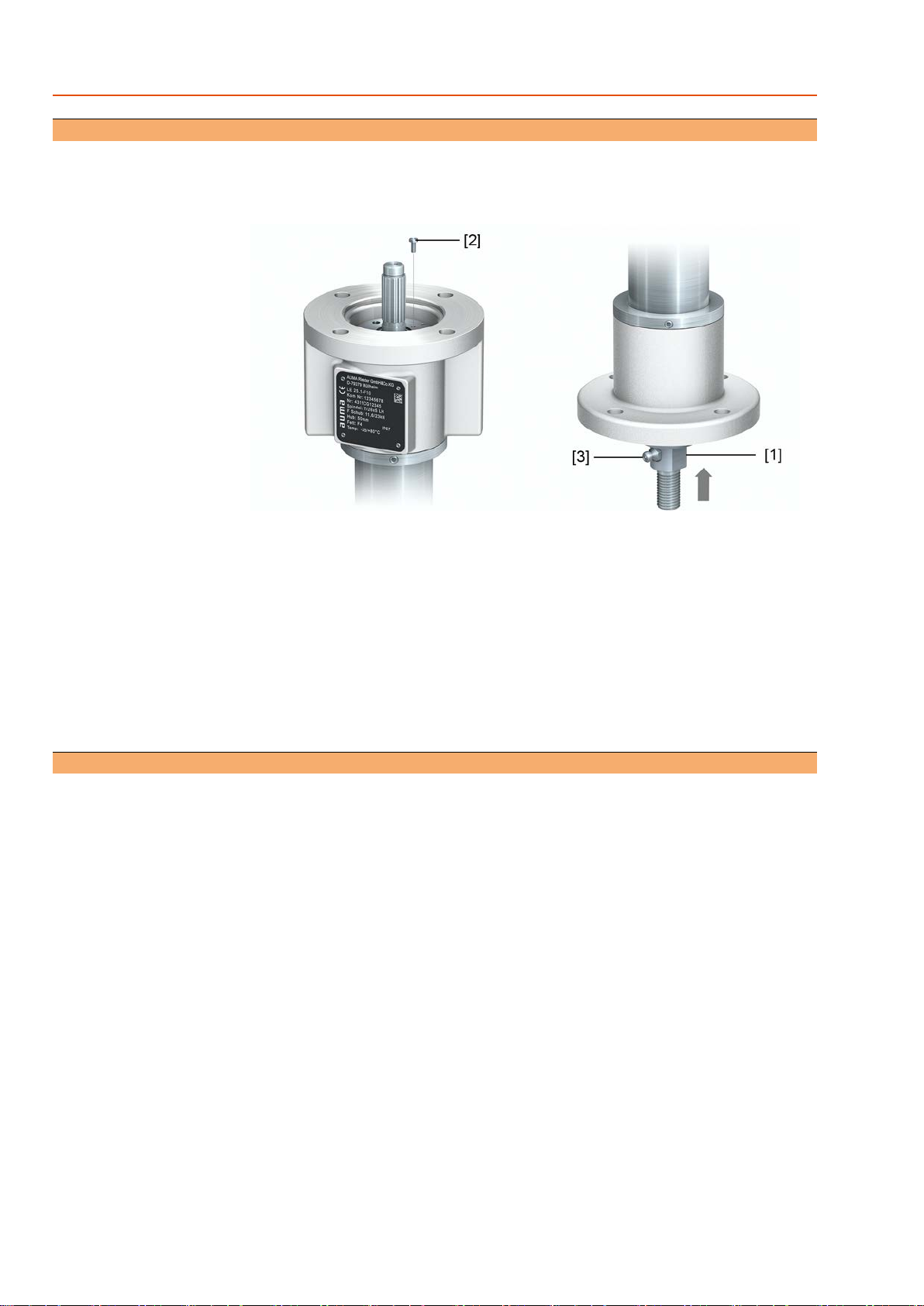
Figure 6: Grease nipple and vent
[1] Stem
[2] Hexagonal screw for venting
[3] Grease nipple
1. Move stem [1] to upper position (retracted).
2. Remove multi-turn actuator from linear thrust unit.
3. Open vent hole by removing the hexagon screw [2].
4. Press grease into the grease nipple [3] with grease gun until grease emerges
from the vent hole of the hexagon screw [2].
5. Close vent hole again using hexagon screw [2].
6. Mount multi-turn actuator again to linear thrust unit.
6.4. Disposal and recycling
Our devices have a long lifetime.However, they have to be replaced at one point in
time.The devices have a modular design and may, therefore, easily be separated
and sorted according to materials used, i.e.:
●electronic scrap
●various metals
●plastics
●greases and oils
The following generally applies:
●Greases and oils are hazardous to water and must not be released into the
environment.
●Arrange for controlled waste disposal of the disassembled material or for sep-
arate recycling according to materials.
●Observe the national regulations for waste disposal.
16
LE 12.1 –LE 200.1
Servicing and maintenance

7. Technical data
Information The following tables include standard and optional features.For detailed information
on the customer-specific version, refer to the order-related data sheet.The technical
data sheet can be downloaded from the Internet in both German and English at ht-
tp://www.auma.com (please state the order number).
7.1. Features and functions
Features and functions
Short-time duty S2 - 15 min (open-close duty)
Intermittent duty S4 -25 % (modulating duty); based on maximum thrust for modulating torque
100 % load may only be applied for a short time during opening and closing.
Type of duty
YesSelf-locking
Refer to actuator name plateInput speed
LH Stem extension for clockwise rotation of multi-turn actuatorStandard:Closing direction
RH Stem retraction for clockwise rotation of multi-turn actuatorOption:
Standard thread of valve stem (for exact version, refer to actuator name plate)
LE 200.1LE 100.1LE 70.1LE 50.1LE 25.1LE 12.1
48 x 8 LH40 x 7 LH40 x 7 LH32 x 6 LH26 x 5 LH26 x 5 LH
Output drive type
Version with spring-loaded damping device (option)1)
Remaining travelMax. force Fmax
Spring travel to
Fmax
Preload2)
Force for travel
limitation
Spring travel
max.
Type
[mm][kN][mm][kN][mm][kN][mm]
2.211.51.86.81.7154LE 12.1
2.3231.713.82334LE 25.1
237.53223465LE 50.1
2.4643.633.42.8796LE 70.1
1.61284.456.92.71496LE 100.1
1.82174.299.432646LE 200.1
Not suitable for use in potentially explosive atmospheres.1) Tolerance variations of disc springs are not considered.2)
17
LE 12.1 –LE 200.1 Technical data

7.2. Service conditions
Service conditions
–25 °C to +80 °CStandard:Ambient temperature
0 °C to +120 °C
–40 °C to +60 °C
–60 °C to +60 °C
Options:
IP67Standard:Enclosure protection according to
EN 60529
KS:Suitable for use in areas with high salinity, almost permanent condensation, and high
pollution.
Standard:Corrosion protection
KX: Suitable for use in areas with extremely high salinity, permanent condensation
and high pollution.
Option:
Two-component iron-mica combinationBase coating
AUMA silver-grey (similar to RAL 7037)Standard:Colour base
Available colours on requestOption:
Special features for use in potentially explosive atmospheres
The tests to ensure conformity with ATEX directive 2014/34/EU were performed according to the technical data. For other applications,
please consult AUMA.100 % load may only be applied for a short time during opening and closing.Sufficient pause times have to be respected.
II2G c IIC T4 according to ATEX CD 2014/34/EULinear thrust
unit:
Explosion protection
II2G c IIC T4 according to ATEX CD 2014/34/EUMulti-turn ac-
tuator:
Short-time duty S2 - 15 min, max.3 cycles (OPEN-CLOSE-OPEN) based on mean thrust and standard
ambient temperature
Intermittent duty S4 - 25 %; based on maximum thrust for modulating torque
Type of duty
–25 °C to +40 °CStandard:Ambient temperature
–40 °C to +40 °COption:
7.3. Further information
Further information
ATEX Directive: (2014/34/EU)
Machinery Directive: (2006/42/EC)
EU Directives
18
LE 12.1 –LE 200.1
Technical data

8. Spare parts
8.1. Linear thrust unit LE 12.1 –LE 200.1
19
LE 12.1 –LE 200.1 Spare parts

Please state device type and our order number (see name plate) when ordering spare parts.Only original AUMA spare parts should be used.
Failure to use original spare parts voids the warranty and exempts AUMA from any liability. Representation of spare parts may slightly vary
from actual delivery.
TypeDesignationNo.
Outer tube001.0 Inner tube002.1 Nut004.1 Support washer006.1 Sub-assemblyRing nut007.0 Barrel nut008.1 Bearing bush009.1 Sub-assemblyActuator mounting flange011.0 Sub-assemblyOutput mounting flange012.0 Sub-assemblyLocking nut013.0 Sub-assemblyCoupling stud026.0 Sub-assemblyStem028.0 Grub screw513.1 Snap ring535.1 Sub-assemblyOutput drive type B3/B4/E549.0 Parallel key551.1 Radial seal643.0 Axial deep groove ball bearing644.0 O-ring645.0 Wiper ring646.0 Sealing ring647.0 Guide ring648.0
20
LE 12.1 –LE 200.1
Spare parts
This manual suits for next models
6


