Aumuller EMB 7300 Guide

EMB 7300 Radio RWa SyStEM
Instructions for
installation and commissioning

2
Installation Instruction
Radio RWA System
Contents
08
07
06
05
04
03
02
01
Abbreviations
Warning and Safety symbols
Target groups, Intended use
Safety Instructions, Directives and Standards
Data Sheet for EMB 7300 Radio RWA System
Installation of the EMB 7300 Radio RWA System
Storage and Disassembly
Disposal
Warranty and Customer Service
Liability
Certicate
3 - 6
7
8 - 10
11 - 14

3
Installation Instruction
Radio RWA System
aBBREviationS
01
Preliminary remarks
Scale Units
°C Degree Celsius
A Ampere
Ah Ampere hour
kg Kilogramme
m Metre
min Minute
mm Millimetre
s Seconds
V Volt
VE (PU) Packaging Unit
Vpp Residual Ripple (Voltage peak-to-peak)
W Watts
Ω / k Ω Ohm / Kilo-Ohm
General Symbols
AC Alternating Current (50Hz / 60Hz)
DC Direct Current
I Electric Current
L Length
ME Module Space Unit (1 ME = 23 mm)
NC Contact „closed“ (normally closed)
NO Contact „opened“ (normally opened)
P Electric Power
R Electrical Resistance
U Electric voltage
Um Change-over switch
Colour Codes according to IEC 60757
BK black GY grey VT violet
BN brown OG orange WH white
BU blue PK pink YE yellow
GN green RD red
Index of abbreviations
The following abbreviations are used throughout these instructions.
All units of measurement in the instructions are in mm, unless otherwise
stated. General tolerances according to DIN ISO 2768-m.
aP Surface mounted
WxHxD Width x Height x Depth
CAN CAN-BUS
CM Control-Module
COM Common connection
DIN German Institute for Standardisation
DM Drive-Module
EN European Standard
IN Input
LON Local Operating Network
OUT Output
PG Price group
PM Power-Module
PS Power supply
RM6 Relay-Module
RWA Smoke and heat exhaust
SM Sensor-Module
uP Flush mounted
WM Weather-Module
WRG Wind direction transmitter
WaRning and SafEty SyMBolS in thESE inStRuctionS:
The symbols used in the instructions must be strictly observed and have the following meanings:
Failure to comply with these warnings may result
in permanent injury or death.
Failure to comply with these warnings may result
in permanent injury or death.
Failure to comply with these warnings may result
in minor or moderate (reversible) injuries.
Failure to comply with these notes may result in
property damage.
!
WaRning
!
dangER
!
caution
notE
Useful Note
for optimal installation.
Note regarding system conguration
setting options via the „Alpha“ conguration
software.
USB
Caution / Warning
Danger from electric current.
Attention / Warning
Risk of damage / destruction of Control Units, drives and
/ or windows.
!

4
Installation Instruction
Radio RWA System
These instructions are intended for qualied personnel
trained in electrical engineering and skilled operators
of systems for natural smoke ventilation (NRA / RWA)
(natural smoke exhaust / smoke and heat exhaust) and
for natural ventilation via windows, who have knowledge
of the operating modes and residual risks of the system.
This device is not intended for use by
persons (including children) with limited
physical, sensory or mental abilities or
lack of experience and/or knowledge.
taRgEt gRoup
!
WaRning
By connecting the window drives with a
control device and commissioning them,
the installer of the entire system becomes
the manufacturer of the electric window!
The installer may be required to carry out
a risk assessment of the entire system in
accordance with the Machinery Directive
2006 / 42 / EC if the use or operation of
the control unit or the connected window
drives deviates from the intended use!
notE
intEndEd uSE
Area of Application / Scope of Application
This control device is intended for the supply and cont-
rol of electrically operated windows in façade and roof
areas. The main task of this product, in combination
withtheelectromotivewindow,istoremovehotsmokeand
fumes in case of a re in order to save human lives and pro-
tect material assets. In addition, the electromotive window
ensures the supply of fresh air for natural ventilation
of the building.
Intended use according to the Declaration of Con-
formity
The control device is designed for xed installation and
electrical connection as part of a building.
In accordance with the attached Declaration of Con-
formity the control device, in combination with electromoti-
ve drives from Aumüller, is approved for proper use on a
power-operated window:
• Application for natural ventilation
installation height of the drive and the bottom side
of the sash at least 2.5m above the oor, or
opening width at the HSK of the operating unit
< 200 mm with a simultaneous speed of the HSK in
closing direction of < 15 mm/s.
• Application as NRWG (natural smoke and heat
exhaust ventilator) according to EN12101-2 without
dual function for natural ventilation.
notE
We recommend the exclusive use of
auMüllER system components, as their
compatibility is carefully checked at
the factory. auMüllER does not assume
any liability for the proper functioning
of third-party components. For applica-
tions and connections other than those
explicitly stated in these instructions,
the express written consent of auMüllER
is required. The use of applications and
components not expressly authorised by
auMüllER shall also be considered as not
in accordance with the regulations even
if their proper functioning can be proved
when they are put into operation (e.g. by
approval under building law).
Preliminary remarks
01

5
Installation Instruction
Radio RWA System
!
WaRning
Scope of application
The control device shall only be used according to its in-
tended use. For additional applications, please contact the
manufacturer or their authorised dealer.
Installation
These instructions are intended for competent and safety-
conscious electrical installers and/or qualied personnel
with knowledge of the electrical and mechanical installa-
tion of drives and control systems.
Mounting Material
The required mounting material must be modied to t the
applied load.
Routing cables and electrical connection
The laying or installation of electrical cables and
connections may only be carried out by approved
specialist companies. Never operate the drives, controls,
operating elements or sensors on operating voltages and
connections contrary to the manufacturer’s specications.
SafEty inStRuctionS
It is important to follow these instruc-
tions for the safety of persons. These
instructions must be kept in a safe place
for the entire life of the product.
The planning and calculation of the line
network is the responsibility of the building
owner, their agents or the commissioned in-
staller, and must be carried out in accordance
with the statutory regulations.
notE
All relevant regulations must be observed during instal-
lation, particularly:
• VDE 0100 Installation up high-voltage systems up to
1000 V
• VDE 0815 Installation cables and - / conductors
• Model Cable Systems Directive (MLAR).
The cable types, cable lengths and cross-sections must be
selected in accordance with the manufacturer’s technical
specications. If necessary, the cable types must be appro-
ved by the responsible local authorities and power supply
companies.
The mains supply line of the Control Unit must
be secured separately by the customer and
provided with an all-pole disconnecting de-
vice. After opening the system housing, live
parts are exposed. The system must be dis-
connected from the power supply and batte-
ries before any work can be carried out on the
Control Unit.
Clamping points must be checked for tightness of screw
connections and cable ends. The accessibility of junction
boxes, terminal points and external drive controls for main-
tenance work must be ensured.
Commissioning, operation and maintenance
After installation and after every change to the setup, all
functions must be checked by a test run. After completion
of the installation, the end user must be instructed in all im-
portant operating steps. If necessary, they must be informed
of any remaining risks / dangers.
The end user must be informed about the intended use of
the system and, if necessary, about the safety instructions.
Cables must be laid in such a way that they
are not sheared off, twisted or bent during
operation. It is recommended to carry out an
insulation measurement of the line network of
the system and to document it.
notE Put up warning signs!
Before working on the system, it must be com-
pletely disconnected from the power supply
and emergency power supply (e.g. batteries)
and secured against accidental reconnection.
When working in the Control Unit, the work-
place must be secured against unauthorised
access. It must be ensured that unauthorised
persons cannot open the Control Unit.
!
WaRning Carefully check all functions of the sys-
tem before releasing it for operation.
The installation instructions of system components (smo-
ke detector, natural smoke and heat exhaust ventilators,
drives, etc.) are part of the documentation of the overall
system and, like the installation and operating instructions
for the control unit, must be kept accessible to authorised
specialists throughout the service life of the system.
Software terms and conditions
The Control Unit is congured at the factory for its intended
use (standard conguration). With the software specially
developed for this Control Unit, the factory setting can be
quickly and easily adapted to suit specic requirements. In
addition, the system status can be saved, recalled and prin-
ted out.
01
Preliminary remarks
Changeable standard congurations are high-
lighted in these instructions. The range of
functions of the unlicensed version can be ex-
tended by license activation payment.
USB

6
Installation Instruction
Radio RWA System
01
Preliminary remarks
Declaration of Conformity
The control device is manufactured and tested for its speci-
c intended use according to European guidelines. The res-
pective Declaration of Conformity is available. If the use or
operation of the control unit or the connected window dri-
ves deviates from this, a risk assessment must be carried out
for the entire power operated window system and a decla-
ration of conformity must be issued in accordance with the
Machinery Directive 2006/42/EC and the CE mark attached.
diREctivES and StandaRdS
During installation and electrical connection, the latest
country-specic laws, ordninances, regulations and stan-
dards must be adhered to without fail.
These are, for example:
State building code with special building regulations such
as:
- Industry Building Directive
- Ordninance on Places of Assembly etc.
MLAR - Model Piping Systems Directive
Regulations of the Fire Protection Authorities TAB
(technical connection conditions) of the Energy Sup-
ply Companies
Trade Association Regulations, such as:
- ASR A1.6 and 1.7(substitute for BGR 232)
Further standards and guidelines, such as:
EN 60335-2-103 Safety of electrical appliances
EN 60730-1 Automatic electrical controls
EN 12101-10 / prEN 12101-9 (ISO 21927-9/10)
Smoke and heat control systems
DIN 4102-12 Functional maintenance of electric
cable systems
VDE 0100 Installation of high-voltage systems up
to 1000 V
VDE 0298 Use of Cables
VDE 0815 Installation cables and lines
VDE 0833 Alarm systems
VdS-Guidelines: 2593, 2581, 2580, 2592
Accident Prevention Regulations, in particularly:
- VBG 1 „General Regulations“ and
- VBG 4 „Electrical Systems and Equipment“.
The relevant national laws, regulations, standards and safe-
ty provisions apply to the marketing, installation and com-
missioning outside of Germany.
The installer is responsible for the proper installation, ope-
ration and the issuing of a Declaration of Conformity accor-
ding to European Guidelines.
The system requirements (see chapter „SyStemS Configura-
tion of Software“) must be checked before installation. The
„Software clause for the provision of standard software as
part of deliveries“ of the ZVEI (Central Association of the
Electrical Engineering and Electronics Industry) is conside-
red to be legally binding upon installation. See our website:
(www.aumueller-gmbh.de)
Therefore, we recommend protecting the operating system
and the software from unauthorised access (e.g. by use of
a password) and attending the training provided by the
manufacturer.
Spare Parts
System components should only be replaced with spare
parts of the same manufacturer. The manufacturer’s liabi-
lity, warranty and customer service are considered void if
third-party products are used. Only original spare parts from
the manufacturer are to be used for system extensions.
Ambient Conditions
The product must not be exposed to impacts or falls,
vibrations, humidity, aggressive vapours or other harmful
environments unless approved by the manufacturer for one
or more of these environmental conditions.
• Operation:
Ambient Temperature: -5 °C … +40°C
Relative Humidity: < 90% up to 20°C;
< 50% up to 40°C;
no condensation
• Transport / Storage:
Storage Temperature: 0°C … +30°C
Relative Humidity: < 60%
Accident prevention regulations and employer‘s
liability insurance association guidelines
When working on, in or on top of a building or part of a
building, the specications and instructions of the respecti-
ve Accident Prevention Regulations (UVV) and Employers‘
Liability Insurance Associations (BGR / ASR) must be obser-
ved and complied with.
The conguration software of the control de-
vice largely excludes damage due to incorrect
settings. As a precaution, we would like to
emphasise that auMüllER, as manufacturer,
cannot be held liable for damages resulting
from the use of auMüllER software, because
auMüllER itself has no inuence on a per-
fect systems environment or object-specic
systems conguration.
USB

7
Installation Instruction
Radio RWA System
Radio HSE and Radio Receiver
The Radio HSE are connected to the Radio Receiver by
radio (ISM band) and exchange a data packet (Ping) every
96 seconds to signal the “life status”.
If a signal is generated on the Radio HSE (trigger button,
reset button or fault) an encrypted data packet is imme-
diately sent back to the Radio Receiver with a conr-
mation packet.
The radio system uses 6 frequencies for the Radio HSE. The
total number of all Radio HSE must not exceed 10 detec-
tors per system.
• Long service life of the battery-powered Radio HSE
• High security for all transmission channels
- AES encrypted packets in the event of triggering
- Hand-shake for radio and serial data
- Distribution on 6 frequencies against jamming
transmitters
• High range in buildings
- VNA optimised Radio HSE antennas for horizontal
and vertical radio alignment
- 433MHz ISM narrow bandwidth with 1.2kbps
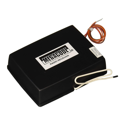
EMB 7300 Radio RWA System: Radio HSE (Transmitter) and Radio Receiver
For comissioning the licensed version of the
conguration software EMB Compact is
absolutely necessary!
!
Connection: Radio Receiver on EMB 7300
1
7 1
1
7 2
Slot for radio module
Plug-in direction:
Antenna connection
towards main board
Data sheet EMB 7300 Radio RWa SyStEM
02
Application: The Radio HSE is used to control the EMER-
GENCY OPEN and EMERGENCY CLOSE functions
via a Radio Receiver in the detector line of the
EMB 7300 RWA Control Unit.
Radio: FM narrow bandwidth
Frequency: 433.100 to 434.600
For the use of Radio RWA, an EMB 7300
rmware V0.1.9 or higher is required.
!
Additional Equipment
Radio Receiver 528738
Radio Antenna including holder 528737
Radio HSE VARIANTS
Radio HSE Plastic red (similar to RAL 3000) 528731
Radio HSE Plastic yellow (similar to RAL 1018) 528732
Radio HSE Plastic grey (similar to RAL 7035) 528733
Radio HSE Plastic blue (similar to RAL 5015) 528734
Radio HSE Plastic orange (similar to RAL 2011) 528735
Inclusive: 3,6 V Lithium-Battery, > 2000mAh, Typ: 14500

8
Installation Instruction
Radio RWA System
installing EMB 7300 Radio RWa SyStEM
InstAllIng step 1:
Select frequency group:
A predened frequency group can be selected for the radio
link of the EMB 7300 Radio RWA via the 4 selection elds
under Frequency Group:
InstAllIng step 2:
Preparing the push-button:
• Remove the battery.
• Hold down the reset key.
• Insert the battery.
• The red LED ashes.
• When the red LED stops ashing, release the reset key.
• The push-button is reset.
InstAllIng step 3:
Set the freqency group on the RWA buttons:
• Remove the battery.
• Press and hold the reset key and the release key
simulatenously.
• Insert the battery.
• All LEDs light up until the keys are released.
• The red LED now ashes for the group number (1 x for
Group A, 2 x for Group B, etc.).
Press the reset key to select the next group and the
release key to accept the currently selected group.
Group A
EMB7300-0102A
Basic Features Frequency Group
Radio RWA
File System Configuration Language Help Absolut ...
Features
Firmware Update
System Features
Drive line 1
Drive line 2
Radio RWA
Frequency Groups (MHz)
Group A 433.100, 433.700, 434.450,
433.300, 434.225, 433.500, 434.000
Group B 433.150, 433.750, 434.500,
433.350, 434.275, 433.550, 434.050
Group C 433.200, 433.800, 434.550,
433.400, 434.325, 433.600, 434.100
Group D 433.250, 433.850, 434.600,
433.450, 434.375, 433.650, 434.150
03
If the network option Radio SHEVs is selected under System
Properites, the following tab appears in the left-hand menu:
„Radio RWA“.
EMB 7300 Radio RWa SyStEM
The licensed version of the „EMB Kompakt“
software is required in order to change the
network options and to programme and con-
gure the radio RWA buttons.
After selecting the network option
„Radio RWA“ and the desired frequency
group (this is set on the system and the
push-button), the change must be saved in
the control panel. No push-buttons can be
programmed before this.
notE

9
Installation Instruction
Radio RWA System
InstAllIng step 4:
Startup Phase on the SHE button:
• After inserting the battery in the RWA button, the
startup phase of the button (boot) begins.
This lasts approx. 20 seconds and is completed as soon
as the green und yellow LED ash simultaneously.
• The button is now ready to be programmed.
InstAllIng step 5:
Programming push-buttons in the system
• When Step 3 is completed, the push-buttons can be pro-
grammed on a Control Unit.
• Start the software and select the tab “Radio RWA”.
There is a „Plus“ button under the selection of
frequency groups.
• When the „Plus“ button is pressed, the system
switches to search mode and sends a “Search Signal” to
all manual call points.
• The signal lasts for 3 minutes.
• On all manual call points
- that do not have an assigned address
- are in the correct frequency group and
- are within reach
the „Triggered LED“ (red LED on the push button)
now starts to ash.
• To complete the programming process, the
„EMERGENCY OPEN“ button in the RWA button must
be pressed. After a few seconds the button is program-
med and appears in the congurator.
Group A
EMB7300-0102A
Basic Features Frequency Group
Radio RWA
File System Configuration Language Help Absolut ...
Features
Firmware Update
System Features
Drive line 1
Drive line 2
Radio RWA
button
„Plus“
EMB7300-0102A
Group B
Wait for manual alarms
2 : 59
File System Configuration Language Help Absolut ...
Basic Features
Features
Firmware Update
System Features
Drive line 1
Drive line 2
Radio RWA
Group AFrequency Group
Radio RWA
EMB7300-0102A
Group B
File System Configuration Language Help Absolut ...
Basic Features
Features
Firmware Update
System Features
Drive line 1
Drive line 2
Radio RWA
Group AFrequency Group
Radio RWA
installing EMB 7300 Radio RWa SyStEM
03

10
Installation Instruction
Radio RWA System
Additional Displays
LED´s Show the current status which the respective
key reports back to.
Battery Indicates the current battery charge level.
Reception Displays the current signal strength of the
button.
Blue
Points
Shows which motor lines (1 or 2 or both) the
button currently triggers.
11-61-04-00
resettIng AButton
To delete the addressing of a push-button (e.g. for pro-
gramming to another installation), the following steps are
necessary.
• Remove the battery.
• Press and hold down„EMERGENCY CLOSE“.
• Insert the battery.
• Red LED ashes.
• When the LED stops ashing, release the push-button.
InstAllIng step 6:
Edit Push-button
To edit a programmed push-button, simply left-click with
the mouse on the desired push-button – the push-button’s
editing menu opens:
Edit manual call point
Name:
Adress:
Drive Line:
Status: Pink ok
AL1
11-61-04-00
AL2
11-61-04-00
Adjustable functions
Name Here you can assign a name for each
push button as free text.
Adress Hardware-bound –
nothing can be changed here.
Drive Lines
Here you can set which drive lines
(1 or 2 depending on the Control Unit
variant) the RWA button should trigger.
Status
Info eld, here the push-button reports
its status (e.g. missing, if it is no longer
recognised).
Colour selec-
tion push
button
Here you can select the colour of the
button for better orientation.
All changes must be saved via the disk in the
editing menu.
Battery Change
The battery of the manual call point must be
changed at least every 2 years (in standard
operation).
In case of frequent malfunctions / tripping,
an annual change may also be necessary. The
exact battery status can be monitored via the
central software.
Normal Operation:
If all push-buttons have been properly pro-
grammed and the system is in normal opera-
tion (no fault is present), the green LED on
the HSE push-button ashes, therefore signal-
ling normal operation.
For energy-saving reasons, the LED on the
radio HSE push-button ashes (on wired
push-buttons, it is permanently lit)
If you want to delete a key which has already
been programmed, you can use the „Trash“
icon in the software.
!
!
!
The respective indicators can be displayed
with a delay of up to 30 seconds depending
on the situation.
!
installing EMB 7300 Radio RWa SyStEM
03

11
Installation Instruction
Radio RWA System
WaRRanty and cuStoMER SERvicEStoRagE and diSMantling
!
The Control Unit should only be stored in places protected from mois-
ture, heavy contamination and high temperatures (not above 30 °C). Do
not remove the packaging until the control unit is ready to be installed.
Disconnect the batteries and store them separately if the control unit has
already been used.
When storing rechargeable batteries it is essential to observe the
following:
If the Control Unit is to be permanently decommissioned, the legal
regulations for destruction, recycling and disposal must be adhered to.
The control unit contains plastic, metal and electrical components as well
as batteries. Replaced batteries contain highly toxic pollutants and must
therefore only be disposed of at the collection points stipulated by law.
Keep the storage time of the lead acid batteries as
short as possible, as the batteries discharge over time.
The batteries must be recharged after seven months
of storage at the latest. For recharging, either use a
suitable charger or connect the batteries to an
EMB Control Unit and supply it with mains voltage.
In both cases the charging time is at least 8 hours
(depending on discharge).
In principle, the following applies:
„General Terms of Delivery for Products and Services of the
Electrical Industry (ZVEI)“.
„Terms of Delivery for the software used“.
The warranty complies with the legal requirements and applies to the
country in which the product was purchased.
The warranty extends to material and manufacturing defects that occur
under normal use.
The warranty period for material delivery is twelve month.
Warranty and liability claims for personal injury and damage to
property are excluded if they are attributable to one or more of the
following cause:
• Improper use of the product.
• Improper installation, commissioning, operation, maintenance or
repair of the product.
• Operating the product with defective, incorrectly installed or non-
functional safety and protective devices .
• Failure to observe the instructions and installation requirements in
these instructions.
• Unauthorised structural changes to the product or accessories.
• Catastrophes caused by foreign bodies and Acts of God.
• Wear and tear.
The contact person for possible warranties or for spare parts or accesso-
ries is the branch ofce responsible for you or your responsible clerk at:
.
The contact details are available on our website
(www.aumueller-gmbh.de)
liaBility
Product changes and product adjustments can be made without prior
notice. Illustrations are not binding. Despite the greatest possible care, no
liability can be accepted for the content of these instructions.
diSpoSal
Do not throw electrical appliances in the household waste! According to
the European Directive 2012 / 19 / EU on Waste Electrical and Electro-
nic Equipment (WEEE) and its implementation in national law, electrical
equipment that is no longer usable must be collected separately and sent
for environmentally friendly recycling.
storage / Warranty anD Customer serviCe / liability
04
Before removing the Control Unit, it must be dis-
connected from the mains at all poles!

12
Installation Instruction
Radio RWA System
04

13
Installation Instruction
Radio RWA System
04

14
Installation Instruction
Radio RWA System
04

15
Installation Instruction
Radio RWA System
This is aTranslaTion of The original german insTrucTions for insTallaTion and commissioning
Important Note:
We are aware of our responsibility to act with the greatest possible care in the presentation of products that save lives and preserve value.
Although we make every effort to keep all data and information as up-to-date as possible, we cannot guarantee that it is free of errors.
The information and data contained in this document are subject to change without notice.
The distribution and reproduction of this document, as well as the use and communication of its contents are not permitted unless specically authorised.
Offenders will be held liable for the payment of damages. All rights reserved in the event of the granting of a patent or registration of a utility model.
For offers, deliveries and services the terms of business and delivery of Aumüller AutomAtIc gMBhshall exclusively apply.
With publication of these instructions all previous editions become invalid.
cERtificatE and
dEclaRation of confoRMity
We declare that the product described under “Data
Sheet” is in compliance with the following guidelines
under our sole responsibility:
• 2014/30/EU
Directive relating to Electro-Magnetic Compatibility
• 2014/35/EU
Low voltage Directive
We further declare that the drive is a partly permanent
machine according to the European machinery directiv
(2006/45/EG).
Technical documents and explanations at company:
Aumüller AumAtIc GmbH
Gemeindewald 11
D-86672 Thierhaupten
Ramona Meinzer
Managing Director (Chairwoman)
The proof of the application of a quality management
system is for company:
Aumüller AumAtIc GmbH
according to the certication basis DIN EN 9001 as well
as the installation and conformity declaration are avai-
lable via the QR code below or directly on our website:
(www.aumueller-gmbh.de)
notE:
04

90000029201_V0.3_KW51/20
Other manuals for EMB 7300
1
Table of contents
