auna C-300 User manual

www.auna-multimedia.com
C-300
Auto-Endstufe
Car Hi Amplier
10032115 10032116


3
DE
Sehr geehrter Kunde,
wir gratulieren Ihnen zum Erwerb Ihres Geräts. Lesen Sie die folgenden
Hinweise sorgfältig durch und befolgen Sie diese, um möglichen Schäden
vorzubeugen. Für Schäden, die durch Missachtung der Hinweise und
unsachgemäßen Gebrauch entstehen, übernehmen wir keine Haftung.
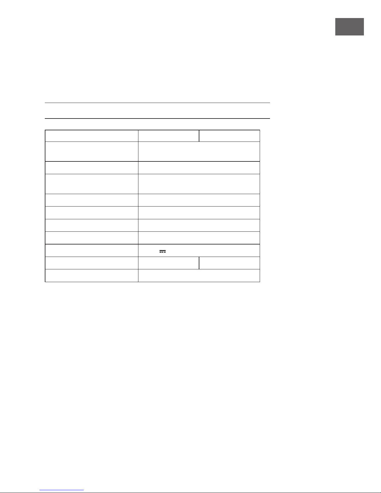
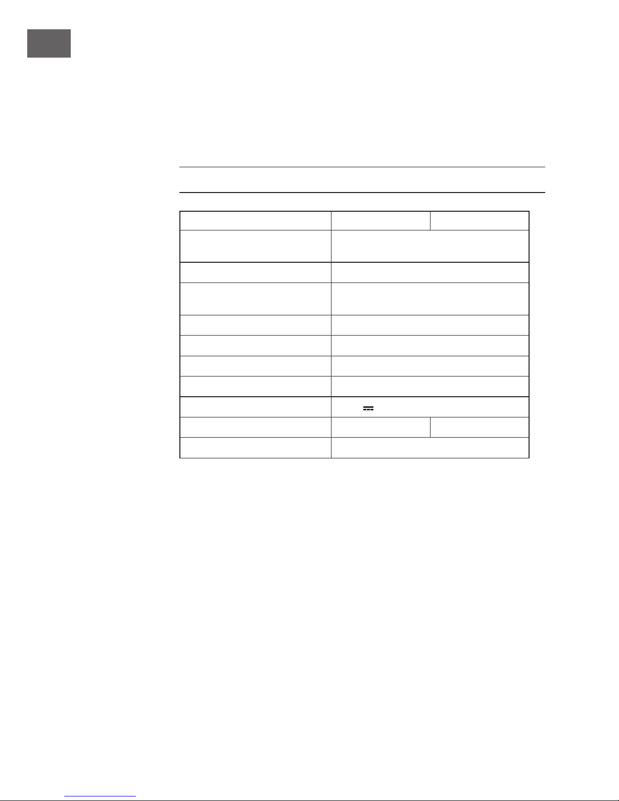
TECHNISCHE DATEN
Artikelnummer 10032115 10032116
Ausgangsleistung 800 W
20 W max. (Mono-)Leistung bei 1 kHz
Frequenzgang 20 Hz - 20 kHz bei 1 dB
Eingangsempndlichkeit Hoch 1,0 - 2,0 V
Niedrig 0,1 - 1.0 V
Signal-Rausch-Abstand > 95 dB
Lautsprecher-Impedanz 4 - 16 Ω
Höhen regelbar ±10 dB
Bass regelbar ±10 dB
Stromversorgung 14, 4 V
Größe 130 x 165 x 42 mm 1901 x 165 x 42 mm
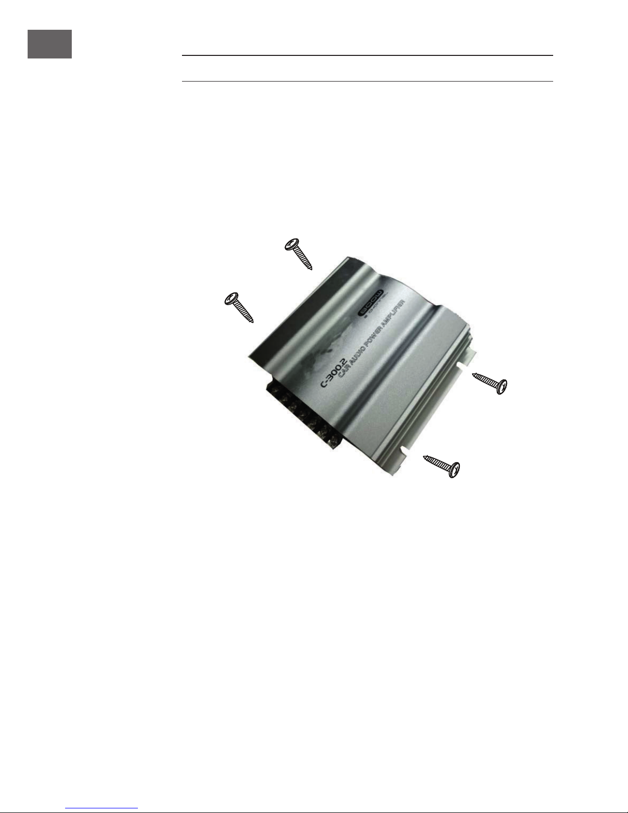
Zubehör Schraubenset, Ersatzsicherung
Eigenschaften
• max. 400 W x 2 Kanal.-Ausgang
• 20 W RMS-Leistung bei einem Klirrfaktor von 0,5 %
• Multi-Anschluss-Fähigkeit für den gleichzeiten Betrieb von Subwoofer
und Satelittenlautsprechern
• Regelbare Höhen
• Regelbarer Bass
• Einstellbarer RCA-Pegel
• Brummstörungsunterdrückung
Stromversorgung
• Ultrastabiles PWM (Impulsbreite moduliertes Signal)
• Thermischer Überlastungsschutuz

4
DE
• Ferneinschaltung
Allgemein
• Abschaltung von Störspannungsrauschen.
• Anschaltverzögerung
• Lautsprecherkurzschlussschutz
• ATC-Einheit- Sicherungsschutz
STROMKABELANSCHLUSS
• Da es sich um ein Hochstromgerät handelt, ist die Verbindung des
Stromkabels sehr wichtig.
• Verbinden Sie das rote Kabel mit dem (+) Pol Ihrer Batterie unter
Verwendung des Kabels mit dem Sicherungshalter.
Verbindung des Fern, Ein- und Abschaltungskabels
• Verbinden Sie das orangene Kabel mit einem geschalteten Stromkabel
des Autoradios. Dies kontrolliert die An- und Abschaltung des
Verstärkers.
• Das geschaltete Stromkabel kann als Antenne des Radios wirken.
Verbindung des Verstärker-Eingangs
• Dieses Gerät kann mit allen Autoradios verwendet werden, die über
Hochleistungsausgänge verfügen.
• Separate Grund Autoradio-Verbindung: Verbinden Sie die Autoradio-
Lautsprecher.
• Allgemeine Grund-Autoradio-Verbindung:Verbinden Sie das negative
Autoradio Lautsprecher-Ausgangskabel mit den zwei verbliebenen
Kabeln +/- rechts und links

5
DE
Verbindung des AUX-Anschlusses
• Verbinden Sie das AUX-Eingangskabel mit dem Chinch-Anschluss wie
beschrieben:
• „Weiß“ zu linken Vorverstärkerausgang des Autoradios. „Rot“ zum
rechten Vorverstärkerausgang des Autoradios
• Bevor Sie den Vorverstärkerausgangdes Autoradios oder anderer
Geräte verbinden, stellen Sie sicher, dass die Impedanz und die
Sensibilität mit diesem AUX-Anschluss übereinstimme.
Eingangs-Sensibilitäts-Kontrolle
• Regeln Sie die Eingangssensibilität zum Autoradio.
Lautsprecheranschluss (Stereo / Mono)
• Verbinden Sie die Lautsprecher wie in Abbildung unten.
REMOTE
GND
B+
POWER
CH1
CH2
FUSE
CH3
CH4
CH1
CH2
BASS
+10
-10
+10
-10
MAX
TRE VOL
MIN
BASS
-10
+10
-10
+10
MIN
TRE
MAX
VOL
IN
CH3
CH4
CH3
CH1
CH4
CH2
REMOTE
GND
B +
CH1CH2
POWER
BASS
HIGH IN
+10
TRE
-10
+10
VOL
-10
MAX
CH1
CH2
MIN
FUSE
REMOTE
GND
B+
POWER
CH1
CH2
FUSE
CH3
CH4
CH1
CH2
BASS
+10
-10
+10
-10
MAX
TRE VOL
MIN
BASS
-10
+10
-10
+10
MIN
TRE
MAX
VOL
IN
CH3
CH4
CH3
CH1
CH4
CH2
REMOTE
GND
B +
CH1CH2
POWER
BASS
HIGH IN
+10
TRE
-10
+10
VOL
-10
MAX
CH1
CH2
MIN
FUSE

6
DE
Hinweis
• Because of high power unit , approx 5A will be drained at peak power.
Using the unit while the engine is stopped may totally discharge the
battery. Please run the engine in using the unit.
• Because of large current ows, please use power supply cord of
suicient capacity if required . ( Larger than 3 mm squre.)
• This unit is designed for use with the Speakers 2~16 impedance. The
speakers must have enough capacity to accept the high power of the
unit.
• Please carefully conrm the rating of the speaker before connection.
2-KANAL-ANSCHLUSS
GARSTEREO
Right channel line output Left channel line output
Car audio
Autoradio
To a metal of the car
BASS
HIGH IN
+10
TRE
-10
+10
VOL
-10
MAX
CH1
MIN
CH2
CH3
CH4
CH1
CH2
BASS
+10
-10
+10
-10
MAX
TRE VOL
MIN
BASS
-10
+10
-10
+10
MIN
TRE
VOL
MAX
IN

7
DE
4-KANAL-ANSCHLUSS
REMOTE
B+
GND
B
B
GARSTEREO
REMOTE
GND
B+
CH1CH2
POWER
FUSE
REMOTE
GND
B+
CH1CH2
POWER
FUSE
REMOTE
GND
B+
POWER
CH1
CH2
FUSE
CH3
CH4
CH3
CH1
CH4
CH2
CH1
CH2speaker
speaker
(Min, 4 ohm)
(Min, 4 ohm)
CH3
CH4
speaker
(Min, 4 ohm)
speaker
(Min, 4 ohm)

8
DE
MONTAGE
Montieren Sie den Verstärker wie in der Abbildung unten beschrieben
Vorsicht: Das Gerät heizt sich stark auf.
Bitte lassen Sie bei der Montage Raum um den Verstärker. Decken Sie den
Verstärker während des Gebrauchs nicht ab.

9
DE
HINWEISE ZUR ENTSORGUNG
Bendet sich die linke Abbildung (durchgestrichene
Mülltonne auf Rädern) auf dem Produkt, gilt die Europäische
Richtlinie 2012/19/EU. Diese Produkte dürfen nicht mit dem
normalen Hausmüll entsorgt werden. Informieren Sie sich
über die örtlichen Regelungen zur getrennten Sammlung
elektrischer und elektronischer Gerätschaften. Richten Sie
sich nach den örtlichen Regelungen und entsorgen Sie
Altgeräte nicht über den Hausmüll. Durch die regelkonforme
Entsorgung der Altgeräte werden Umwelt und die
Gesundheit Ihrer Mitmenschen vor möglichen negativen
Konsequenzen geschützt. Materialrecycling hilft, den
Verbrauch von Rohstoen zu verringern.
8
10R-041283

10
EN
TECHNICAL DATA
Item number 10032115 10032116
Outer power 800 W
20 W max. (Mono-) power at 1 kHz
Frequency respsonse 20 Hz - 20 kHz at 1 dB
Input sensitivity High 1,0 - 2,0 V
Low 0,1 - 1.0 V
Signal ratio > 95 dB
Speaker impedance 4 - 16 Ω
Treble adjustable ±10 dB
Bass adjustable ±10 dB
Power supply 14.4 V
Dimension 130 x 165 x 42 mm 1901 x 165 x 42 mm
Accessory Screw set, spare fuse
Features
• 400W 2 CHANNEL MAXIMUM POWER OUTPUT
• 20W/ CHANNEL RMS CONTINUOUS OUTPUT @ 0.5% THD
• (20Hz TO 20KHz, both channels driven into 2 Load)
• Multi-mode connection capability for simultaneous subwoofer satellite
speaker operation
• Adjustable Bass:+ - 10dB
• Adjustable TREBLE:+ -10dB
• Adjustable RCA level inputs
• Input ground isolation noise rejection circuit
Dear Customer,
Congratulations on purchasing this equipment. Please read this manual
carefully and take care of the following hints on installation and use to
avoid technical damages. Any failure caused by ignoring the items and
cautions mentioned in the operation and installation instructions are not
covered by our warranty and any liability.

11
EN
Power supply
• Ultra stable PWM (Pulse width modulated)
• Power supply (10.5-16V)
• Thermal Protection circuit
• Remote on power switchingTransient noise muting
General
• Transient noise muting
• Turn on delay
• Speaker short circuit protection
• Chassis mount ATC fuse protection
CONNECTION OF POWER CORD
• Since this unit deals with a high power, Large current will ow and the
wiring or power cord is high importance.
• Connect the red wire directly to the (+) terminal of the battery using the
cord with a fuse holder supplied.
• Connect the black wire tightly to an appropriate screw on the metal
part of car after removing paint for proper grounding. Be sure to use the
screw.
Connecrtion of remote on/on wire
• Connect the orange wire to a switched power cord of the car stereo to
be connected to this unit will control the unit power on/o with the car
stereo
• The switched power cord may be obtained an auto antenna cord of the
car stereo.
Connection of booster input (high input)
• This unit can be connected to any car stereo with high level outputs,
common or separated ground outputs.
• Separated ground car stereo connection;-connect car stereo speaker
output cables to the high level input connector (+) and (-),right and left
polarity.
• Common ground car stereo connection;-connect car stereo speakers
negative output cable to the high level input connector to the two
signs(-)and the remaining cables to (+) right ang left.

12
EN
Connection of AUX input
• Connect the AUX input wires with RCA type pin jack as follows:white
to L ch pre-output of the car stereo. Red to Rch pre-output of the car
stereo.
• Before connecting the pre-output of the car stereo or other unit, conrm
the impedance or sensitivity to match with this unit AUX input.
Input sensitvity control
• Adjust the input sensitivity to output of a car stereo connected.
Connection of speaker (Stereo / Mono)
• Connect the speaker wires as per the gures below.
REMOTE
GND
B+
POWER
CH1
CH2
FUSE
CH3
CH4
CH1
CH2
BASS
+10
-10
+10
-10
MAX
TRE VOL
MIN
BASS
-10
+10
-10
+10
MIN
TRE
MAX
VOL
IN
CH3
CH4
CH3
CH1
CH4
CH2
REMOTE
GND
B +
CH1CH2
POWER
BASS
HIGH IN
+10
TRE
-10
+10
VOL
-10
MAX
CH1
CH2
MIN
FUSE
REMOTE
GND
B+
POWER
CH1
CH2
FUSE
CH3
CH4
CH1
CH2
BASS
+10
-10
+10
-10
MAX
TRE VOL
MIN
BASS
-10
+10
-10
+10
MIN
TRE
MAX
VOL
IN
CH3
CH4
CH3
CH1
CH4
CH2
REMOTE
GND
B +
CH1CH2
POWER
BASS
HIGH IN
+10
TRE
-10
+10
VOL
-10
MAX
CH1
CH2
MIN
FUSE

13
EN
Note
• Because of high power unit , approx 5A will be drained at peak power.
Using the unit while the engine is stopped may totally discharge the
battery.
• Please run the engine in using the unit.
• Because of large current ows, please use power supply cord of
suicient capacity if required . ( Larger than 3 mm squre.)
• This unit is designed for use with the Speakers 2~16 impedance. The
speakers must have enough capacity to accept the high power of the
unit.
• Please carefully conrm the rating of the speaker before connection.
WIRING OPERATION FOR STEREO (2 CH)
GARSTEREO
Right channel line output Left channel line output
Car audio
Autoradio
To a metal of the car
BASS
HIGH IN
+10
TRE
-10
+10
VOL
-10
MAX
CH1
MIN
CH2
CH3
CH4
CH1
CH2
BASS
+10
-10
+10
-10
MAX
TRE VOL
MIN
BASS
-10
+10
-10
+10
MIN
TRE
VOL
MAX
IN

14
EN
WIRING OPERATION FOR 4 CHANNELS
REMOTE
B+
GND
B
B
GARSTEREO
REMOTE
GND
B+
CH1CH2
POWER
FUSE
REMOTE
GND
B+
CH1CH2
POWER
FUSE
REMOTE
GND
B+
POWER
CH1
CH2
FUSE
CH3
CH4
CH3
CH1
CH4
CH2
CH1
CH2speaker
speaker
(Min, 4 ohm)
(Min, 4 ohm)
CH3
CH4
speaker
(Min, 4 ohm)
speaker
(Min, 4 ohm)

15
EN
INSTALLATION
Please mount at you option as illustration below using screws and xtrues
with the units
CAUTION: The unit itself will be heated because of its high power.
Therfore, please leave room around the unit in mounting and while in use,
and do not put things on the unit.

16
EN
DISPOSAL CONSIDERATIONS
According to the European waste regulation 2012/19/EU this
symbol on the product or on its packaging indicates that this
product may not be treated as household waste. Instead it
should be taken to the appropriate collection point for the
recycling of electrical and electronic equipment. By ensuring
this product is disposed of correctly, you will help prevent
potential negative consequences for the environment
and human health, which could otherwise be caused by
inappropriate waste handling of this product. For more
detailed information about recycling of this product, please
contact your local council or your household waste disposal
service.
8
10R-041283

17
EN

18
EN


Table of contents
Languages:
Other auna Car Amplifier manuals