Installation Manual
Dimensions of xtures are approximate and may vary ± 6mm (1/4”). Structure measurements must be veried against the unit to ensure proper t.
Product images and specications are for illustrative purposes only, product design may vary.
8
9
2
12
1
6
4
5
7
3
4
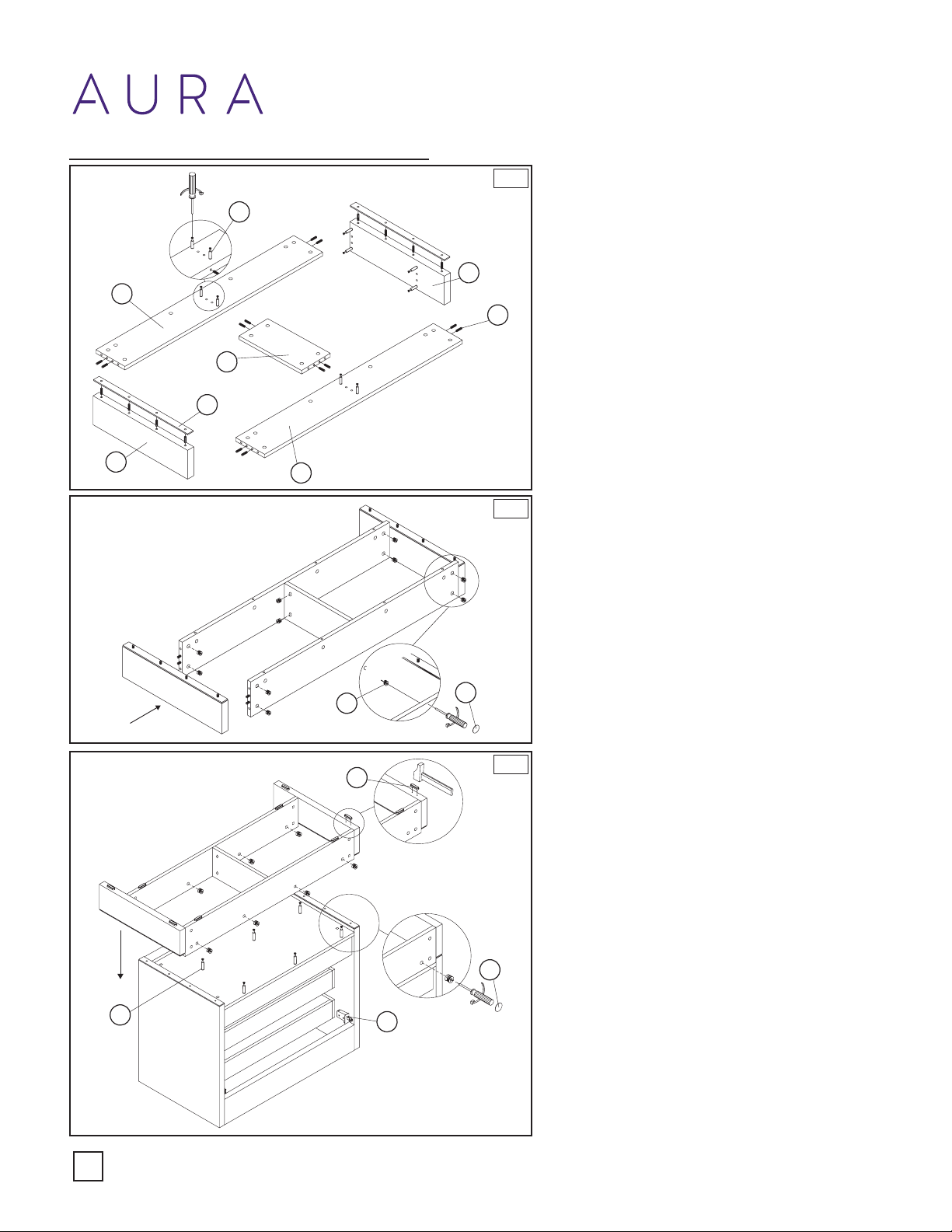
1A.
1B.
1C.
Kickplate Installation
10
11
11
9
Arrange the kickplate pieces in order with Back
Plate (2) towards the wall the Right Plate (1)
to the right of the Back Plate (2) and the Left
Plate (5) adjacent on the other side.
Place the Front Plate (4) and the Inside Plate
(3) as showin the Diagram 1.
Screw in Pegged Connectors (12) in each
designated spot. Four in both the Left Plate
(5) and Right Plate (1) in the outside predrilled
holes. Screw two in both the Back Plate (2)
and the Front Plate (4) in the predrilled holes in
the middle of the board.
Ensure that the Pegged Connectors (12) are
screwed in the outside designated holes as the
smaller holes are designated for the Wooden
Peg (6).
For each plate and place two Pegged
Connectors (12) within the inside holes
predrilled as shown in Diagram 1A.
Take both Chrome Trim (7) and slide them atop
the Left Plate (5) and Right Plate (1). Place a
Pegged Connector (12) in each of the holes.
Gently insert/connect each of the plates into
eachother and use a screw driver to fasten
them together using the enclosed Fasten
Screw (8).
After all points have been fastened with a
Fasten Screw (8) place a Screw Cap (9) over it.
Turn the Vanity Base (11) upside down and
insert the required Pegged Connector (12) in
the bottom of the Vanity Base (11) within its
designated holes.
Take assembled kickplate and rotate it like it is
displayed in Diagram 1C, and ease it down with
the Back Plate (2) ush with the back of the
Vanity Base (11). Guide the kickplate with the
Wooden Peg (6) and Pegged Connectors (12)
into the pre dilled holes in the Vanity Base (11).
Hammer in the Floor Protector (10) onto the
marked positions in Diagram 1C.
Insert the Fasten Screw (8) within each
designed predrilled hole in the kickplate that
correlate to a Vanity Base (11) installed
Pegged Connector (12) and ensure they are
are fastened tightly.
Cap with a Screw Cap (9).
With the assistance of another person, gently
ip the vanity right side up.
1A.
1B.
1C.