AUREL MAG 4M 5026 User manual

MAG 4M 5026
User Manual
Magnetic contact with radio transmission
The magnetic contact wireless MAG 4M 5026 is a sensor able to detect opening or closing doors or windows
and transmits via radio a alarm signal. It is composed of two distinct elements a case containing the
magnetic contact and electronic card normally placed on the frame of the fixture and a small permanent
magnet to fit on the mobile element of the fixture. The working is based on the closing and opening of a
sensor capable to operate within a 5mm radius from the permanent magnet.
MAG 4MHCS is battery power supplied and designed to ensure autonomy of 3-5 years, it is always internally
controlled by a meter charge that forwards via radio the battery life time and warns by a beeper and LED,
the alarm of discharged battery.
The radio transmission operates in the 433.92 MHz ISM band with fixed coding settable by a 9 tree-state
vias dip-switch, features as shown in CI 145026. It starts when the magnet is removed from electrical side
to indicate the alarm condition.
It’s available a led to indicate the radio transmission, alarm and test.
Fig.1 Fig. 2 – Electronic card inside the case
1. Reed: magnetic sensor
2. Magnet: magnet
3. Dip-switch: 9 tree-state vias to set radio code
4. P1 and P2 Setting mode (see "Sensor Configuration) (see the paragraph “HOW IT WORKS”)
5. Battery: Rechargeable lithium type mod. CR2032.
6. LED: light signals (see signaling)
The technical features can be change without forecast. AUR°EL S.p.A doesn’t assume any responsibility for the demages due to the improper use.
AUR°EL S.p.A. Via Foro dei Tigli, 4 - 47015 Modigliana (FC) – ITALY Rev A 11 06 2014
Tel : +390546941124 – Fax: +390546941660 Page 1 of
7
http://www aurel it - email: lab-el@aurel it Preliminary
MAG 4M 5026
User Manual
HOW IT WORKS
Jumpers 1 and 2 (see JP1 and JP2 in picture one) allow to set several kind of works for test and alarm
phase.
FUNCTION P1 P2
RADIO MODE CLOSE OPEN
CALIBRATION FOR MAGNETIC SENSOR OPEN CLOSE
NORMALY WORKING X X
RADIO MODE: It’s a function used during learning procedure to get the radio code in the matched
receiver and to verify the quality of the radio connection. It starts from the closing of JP1 contact and
opening JP2.
The radio transmission is active for 30 seconds, modulated with a code set in the dip-switch(“LEARNING
AND RADIO TEST”).
At the end of transmission the magnetic contact goes in main working mode.
To start again the transmission, disconnect and fit again the JP1 contact.
CALIBRATION OF MAGNETIC SENSOR It’s a function used during learning procedure of the
sensor that helps the installer to place the permanent magnet near the magnetic contact.
It is triggered by the closure of JP2 and JP1 open, the LED switches on when the magnet closes the
magnetic contact and switches off when the contact opens. No radio transmission is activated.
After five minutes from the starting of the procedure, the sensor will come back to the normal function.
To start again the function, disconnect and fit again JP2 contact.
MAIN WORKING: Normally is activated after the fitting of the battery or when “RADIO MODE” AND
“CALIBRATION OF MAGNETIC SENSOR” functions are finished.
The sensor sends a code set by dip-switch when the magnet is removed(see the paragraph “Code radio
features”) .
LED switches on for 100ms to show the radio transmission.
Note The closing of the magnetic contact is not shown in anyway.
Luminous signal
Within the MAG 4M 5026 is present a red led which shows the follow functions
It switches on in presence of any radio transmission( alarm signal, radio test).
In the case of discharge battery (under 2,3 V voltage level) it quickly blinks for two seconds each five
minutes.
In the “calibration of magnetic sensor” function , it switches on permanently if the magnetic contact is
closed.
The technical features can be change without forecast. AUR°EL S.p.A doesn’t assume any responsibility for the demages due to the improper use.
AUR°EL S.p.A. Via Foro dei Tigli, 4 - 47015 Modigliana (FC) – ITALY Rev A 11 06 2014
Tel : +390546941124 – Fax: +390546941660 Page 2 of
7
http://www aurel it - email: lab-el@aurel it Preliminary
MAG 4M 5026
User Manual
Standard setting up
Installation:
1) Remove the front cover and the screw securing the card (see fig. 2).
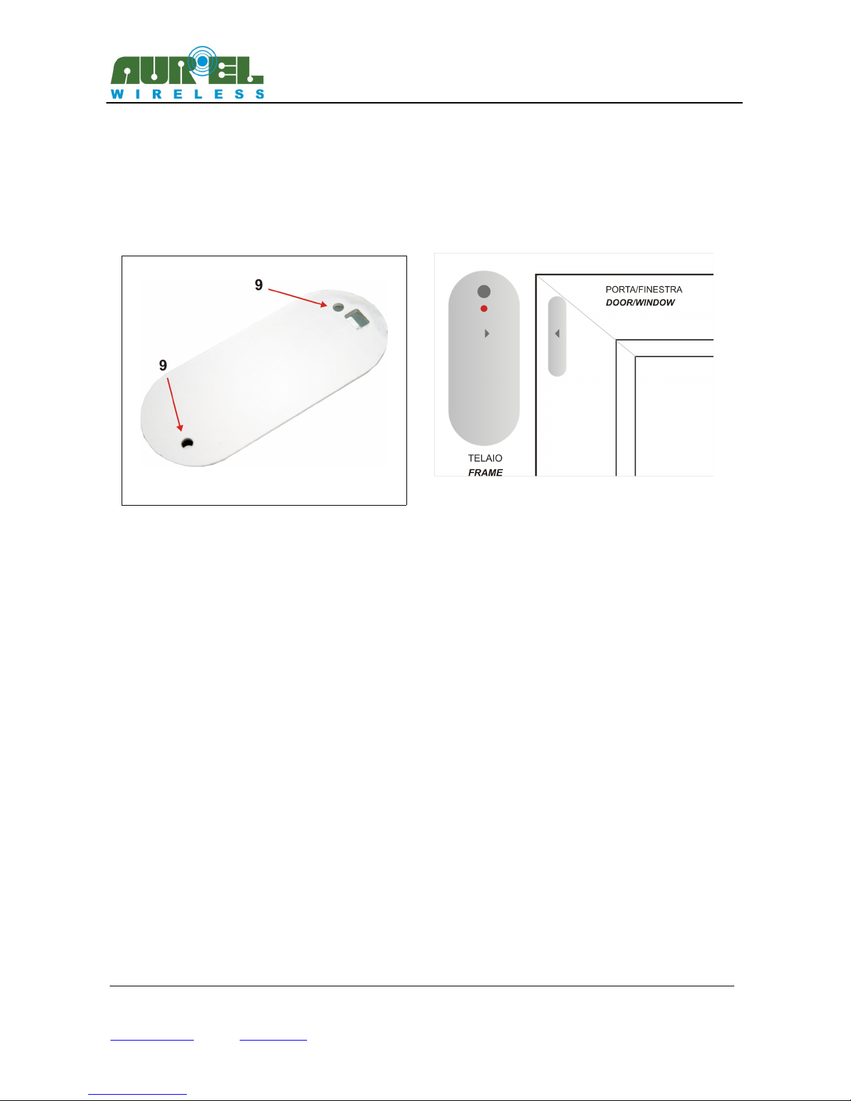
2) Place the bottom of the sensor on the frame of the fixture, making sure to turn the magnetic sensor to
the moving part of the frame where the permanent magnet is placed. Then mark the holes printed on the
bottom box (see fig. 3), 5-6 mm drill with drill and secure the bottom (Fig. 3-4).
3) Remount the card, block with the screw, close JP1 and JP2 contacts (ready for “magnetic sensor
calibration” mode) and mount the battery and the plastic cover.
4) Place the permanent magnet on the mobile part of the fixture trying to match the reference marks in the
case of the sensor and permanent magnet. If the magnet is sufficiently close to the magnetic contact, LED
will switch on indicating the closure of the magnetic contact. However, the sensor will not be installed at a
distance greater than 30mm from the permanent magnet.
Learning procedure and radio test:
Prepare the receiver side in the learning mode.
Activate the "radio mode" of the MAG 4M 5026 by closing of JP1 contact and JP2 opening.
The radio transmitter will send a modulated signal for 30 seconds with radio code set by 9 vias dip-switch.
Note The installation of MAG 4M 5026 metal frames can cause radio performance losses. For critical
installations it advices to test the quality of the radio signal received with a receiver with RSSI output(for
more details see Aurel wireless catalogue).
The technical features can be change without forecast. AUR°EL S.p.A doesn’t assume any responsibility for the demages due to the improper use.
AUR°EL S.p.A. Via Foro dei Tigli, 4 - 47015 Modigliana (FC) – ITALY Rev A 11 06 2014
Tel : +390546941124 – Fax: +390546941660 Page 3 of
7
http://www aurel it - email: lab-el@aurel it Preliminary
Fig.4 Typical installation
Fig.3 fori per montaggio a parete

MAG 4M 5026
User Manual
Battery substitution
The substitution of the battery must be carried out when the LED of the sensor, independently from alarm
status, it quickly blinks for two seconds each 5 minutes(alarm signal for discharged battery).
In this case the battery is not completely finished and it can ensure a couple of weeks of working.
For the replacement procede as follow
Remove the cover and replace the litium 3V mod. CR2032 battery paying attention to the polarity, see
picture number 6.
In order to get a longer life time, the choise of 5 years deadline battery is advised. The accidental reversal of
polarity of the batteries does not cause the breaking of the circuit and discharging them. In the case of
loosing of substances , remove it taking care to not get in contact with them. Throw used batteries in
respect of the normative. See the section 'Information for users'.
Fig. 6 – Battery substitution
Technical features
Min Typical Max U.M.
Electrical parameters
Voltage supply (1) 2,1 3,0 3,6 Volt
stand-by current supply
3 Volt power supply 3 uA
Current supply during alarm
3 Volt, led on, radio transmission on 7 mA
Low battery voltage consumption 2,25 2,3 2,35 Volt
Radio transmission
Standard frequency OOK modulation 433,92 MHz
Effected Radiated Power 1 mW
ERP second harmonic < 1GHz -36 dBm
ERP third harmonic > 1GHz -30 dBm
Radio coding CI 145026
Electromagnetic immunity 10 V/m
The technical features can be change without forecast. AUR°EL S.p.A doesn’t assume any responsibility for the demages due to the improper use.
AUR°EL S.p.A. Via Foro dei Tigli, 4 - 47015 Modigliana (FC) – ITALY Rev A 11 06 2014
Tel : +390546941124 – Fax: +390546941660 Page 4 of
7
http://www aurel it - email: lab-el@aurel it Preliminary

MAG 4M 5026
User Manual
Working temperature -20 +70 °C
Case dimensions TBD mm
(1) 3V litium battery size CR2032
Radio code features
MAG AM 5026 implements a fixed code radio protocol with the possibility to set 19683 different codes
through the 9 vias three-state dip-switch inside the enclosure.
The setting of radio code is carried out before of the fitting of the battery and it will be learned during the
inclusion of the same.
During the normal working, any changing of the dip-switch will be ignored. The radio code is unique ( that
one set by dip-switch) and it starts when the magnet is removed by the enclosure or at the activation of the
“RADIO MODE” procedure.
In order to allow the setting of the complementary decoding in the receiver side, below is shown the time
diagram of the physical protocol and timing features
The technical features can be change without forecast. AUR°EL S.p.A doesn’t assume any responsibility for the demages due to the improper use.
AUR°EL S.p.A. Via Foro dei Tigli, 4 - 47015 Modigliana (FC) – ITALY Rev A 11 06 2014
Tel : +390546941124 – Fax: +390546941660 Page 5 of
7
http://www aurel it - email: lab-el@aurel it Preliminary
Table of contents
Other AUREL Accessories manuals


