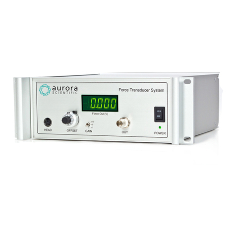
Aurora Scientific miniPID 200C User manual

miniPID Instruction Manual
Model: 200C
© Aurora Scientific, 2023 VER. 1.00
page 2
Copyright © 2023 Aurora Scientific.
Aurora Scientific
25 Industry Street
Aurora, ON, Canada L4G1X6
Tel: 1-905-727-5161
Toll Free (N. America): 1-877-878-4784
Fax: 1-905-713-6882
Email: techsupport@aurorascientific.com
Web Site: www.AuroraScientific.com

miniPID Instruction Manual
Model: 200C
© Aurora Scientific, 2023 VER. 1.00
page 3
Revision History
Date
Version
Number
Document Changes
04-Oct-2023
1.0
Initial Draft

miniPID Instruction Manual
Model: 200C
© Aurora Scientific, 2023 VER. 1.00
page 4
Table of Contents
1Introduction ..................................................................................................................................... 5
1.1 ....Operating Principle........................................................................................................................... 5
2Quick Start Guide ............................................................................................................................. 7
2.1 ....Package Contents............................................................................................................................. 7
2.2 ....First Time Operation of the 200C miniPID ........................................................................................ 8
3General Operating Procedure ........................................................................................................ 11
3.1 ....Description of System Components ................................................................................................ 11
3.2 ....Choice of Tracer Gas....................................................................................................................... 12
3.3 ....Troubleshooting ............................................................................................................................. 13
4Calibration, Instrument Tuning and Maintenance ......................................................................... 15
4.1 ....Calibration...................................................................................................................................... 15
4.1.1 Calibrated Gas Mixtures Technique......................................................................................... 16
4.1.2 Simple Gas Mixing Technique.................................................................................................. 16
4.1.3 Mass Flow Meter Gas Mixing Technique................................................................................. 17
4.2 ....UV Lamp Cleaning, Tuning and Replacement................................................................................. 17
4.2.1 Lamp Removal and Cleaning ................................................................................................... 17
4.2.2 Lamp Tuning............................................................................................................................ 17
4.2.3 Lamp Replacement.................................................................................................................. 18
4.3 ....Maintenance .................................................................................................................................. 18
4.3.1 Pump ....................................................................................................................................... 18
4.3.2 Detection Cell Cleaning ........................................................................................................... 20
5Performance Guarantee, Technical Support, Warranty and Repair Information........................... 21
5.1 ....Performance Guarantee................................................................................................................. 21
5.2 ....Technical Support ........................................................................................................................... 21
5.3 ....Technical Support Contact Information and Return Shipping Addresses........................................ 21
5.4 ....Warranty ........................................................................................................................................ 22
5.5 ....Returning Products to Aurora Scientific for Repair ......................................................................... 23
6Specifications ................................................................................................................................. 25
7Appendix A - Compounds Detectable with the miniPID Sensor ..................................................... 26

miniPID Instruction Manual
Model: 200C
© Aurora Scientific, 2023 VER. 1.00
page 5
1Introduction
The miniPID fast-response photo-ionization detector combines small size, fast response, and high
sensitivity in an easy-to-use, competitively priced package. The sensor has a true frequency response of
330 Hz with a 10-90% rise time of 0.6 msec. The detection limit is 50 ppb (parts per billion) propylene gas
in air and the full-scale measurement range is 600 ppm (parts per million). The miniPID has been
designed to provide high frequency concentration measurements in wind tunnels, test chambers and in
the atmosphere.
1.1 Operating Principle
Inside the miniPID photo-ionization detector (PID) a gas or vapour sample is exposed to high intensity
ultraviolet light that ionizes the molecules of chemical substances. Ions and electrons are collected on
electrodes within the detector cell creating a current proportional to the contaminant concentration.
Ionization depends on the minimum energy needed by a molecule to produce ions and this energy
(ionization potential) is different for each chemical substance. The molecules of most permanent gases
(including the constituents of air: nitrogen, oxygen, carbon dioxide, argon, etc.) are not ionized, as they
require a photon energy level higher than that generated by the lamp. Molecules having ionization
energy levels below the lamp energy (10.6 eV) are the ones that are ionized. Appendix A contains a list of
the ionization potentials of many common substances.
Figure 1 200C Controller

miniPID Instruction Manual
Model: 200C
© Aurora Scientific, 2023 VER. 1.00
page 6
Figure 2 200C miniPID Sensor Short Mount
Since the PID is sensitive to any gas with an ionization potential below 10.6 eV, the output of the device
should be viewed as an expression of the total ionizables present. Because of this, the accuracy of the
miniPID is dependent on the presence of interference gases.
Figure 3 200C miniPID Sensor Long Mount

miniPID Instruction Manual
Model: 200C
© Aurora Scientific, 2023 VER. 1.00
page 7
2Quick Start Guide
This quick start guide will provide you with basic information that will allow you to get your new 200C
miniPID up and running as quickly as possible.
2.1 Package Contents
The 200C miniPID was shipped in a single box. Unpack the box and check the contents against the list
provided below. If there are any issues with what you received, please contact Aurora Scientific as soon
as possible.
Item
Description
200C Controller
Main controller including power supply pre-set to the
power used in your country, suction pump, control
electronics, and a 2U, ½-rack, rack-mountable
enclosure.
251A Interconnection Cable
The interconnection cable consists of a power cable, a
signal cable, and a suction tube all contained within a
woven nylon jacket and terminated with connectors on
each end. The cable is 305 cm (120") long to allow the
controller to be mounted outside of a wind tunnel or
test chamber.
200C-S or 200C-L Sensor Head
The sensor head contains the ultra violet (UV) lamp,
lamp drive electronics, sample inlet, detection cell, and
a pre-amplifier.
200C Series Accessories
Accessories include power cord, tubing, fittings, and
some tools.
Table 1 Items included with a 200C Series Force Transducer
For further description of the components of the system, see Section 3.1.

miniPID Instruction Manual
Model: 200C
© Aurora Scientific, 2023 VER. 1.00
page 8
2.2 First Time Operation of the 200C miniPID
1. The sensor head can be configured with a short or long mount. The short mount includes a side
plate that includes ¼-20 tapped holes in two directions (this is the same thread that is used on
cameras). The tapped holes can be used to attach the head to experimental apparatus or to a
standard camera tripod. The long mount includes a rear plate with a ¼-20 tapped hole and a rod
with a ¼-20 threaded end. The rod can be screwed into the rear plate and then a standard lab
clamp, or other user supplied clamp, can be used to grasp the rod, and thereby mount the sensor
head in the desired location with the inlet needle either facing into the flow or perpendicular to
the flow (see photo 1 below for an example of this mounting technique). The miniPID will
operate in any orientation but care should be taken to protect the instrument from rain or
moisture, excessive dust or dirt, and mechanical shock. Note: The sensor has not been designed
for exposure to weather.
2. Plug the power cord into an AC power socket and into the back of the miniPID controller. Plug the
sensor cable and sample hose into the front of the miniPID controller and into the sensor head.
Tighten the connector screws on the DB-9 connector used on the front panel of the controller.
Loose connections can greatly increase sensor noise.
3. Connect a data acquisition computer, a voltmeter, an oscilloscope, or a chart recorder to the BNC
Out connector on the controller front panel. Because of the wide dynamic range and fast
response of the sensor, it is recommended that a 16-bit analog-to-digital converter (ADC) be used
to digitize the output signal. The ADC should be set to unipolar input with a 0 to 10-volt range.
The output of the miniPID controller is filtered through an 8th order Butterworth low-pass anti-
aliasing filter. The cut-off frequency of this filter is 1,000Hz. It is recommended that the ADC
sampling frequency be set to at least 4 times the cut-off frequency of the low-pass filter (4,000Hz
sampling frequency). Over sampling is crucial if aliasing of the data is to be avoided.

miniPID Instruction Manual
Model: 200C
© Aurora Scientific, 2023 VER. 1.00
page 9
Photo 1 miniPID sensor in use at Prof. Ring Carde's lab,
Dept. of Entomology, University of California, Riverside.
4. Turn the power switch ON. The pump will start immediately but the UV lamp may take up to 1
minute to light. Monitor the "Lamp" LED on the controller front panel. If this LED does not light
within 3 minutes switch the power off, wait about 2 minutes and then try again. If the lamp does
not light after repeated attempts, then consult the troubleshooting and maintenance section of
this manual. Once the UV lamp is lit allow the sensor to warm up for at least 30 minutes before
taking data.
5. When the sensor has warmed up, set the Pump switch to the High flow rate setting and ensure
the Flow Adjust knob is fully closed (turned fully clockwise). This will provide the maximum flow
rate and the fastest response for the instrument.
6. With the sensor drawing clean air, depress the Zero pushbutton to zero the output. The zero
procedure takes a few seconds and when it is complete the Zero LED will light. Note: the
instrument has been adjusted at the factory so that the zero LED is illuminated green if the
output is within 50mV of zero.
7. Release a tracer gas and observe the signals on the front panel LED indicator. Adjust the tracer
flow rate or sensor flow rate until signals can be seen which illuminate most of the LEDs. An
Offscale red LED is included next to the meter to indicate signals that exceed 10 volts. If the red
LED turns on, then lower the source strength of the tracer gas until it turns off. Note: if the tracer
gas is release into free air, then the miniPID output will appear very unstable (rapidly increasing
and decreasing signal that may appear to be noise), this is normal as the instrument is measuring

miniPID Instruction Manual
Model: 200C
© Aurora Scientific, 2023 VER. 1.00
page 10
the high frequency concentration fluctuations in the dispersing plume of tracer gas. For the
purposes of determining correct operation, or for calibration, it is recommended that the tracer
be delivered to the head through a 1/8”ID tube placed loosely over the inlet needle on the head.
This ensures no entrainment of air in the tracer gas and therefore no concentration fluctuations.
8. It is normal for the output of the miniPID to drift slightly with time. This drift occurs mainly in the
sensor head circuitry.
9. It is normal for the sensor head to become slightly warm to the touch.
10. The as-shipped configuration of the miniPID Controller has the sample air exiting the controller
through a stainless-steel muffler (located on the controller rear panel). In some cases, it may be
preferable to have the air exit in a different location, for example within the test chamber. For
this situation remove the muffler (using a 5/16" wrench) and mount the 1/8" tube connector
supplied with the instrument accessories. Use a 1/4" OD by 1/8" ID vinyl tube to connect the
exhaust fitting to the test chamber or other location where you want the flow to exit to.
At this point the miniPID should be set up and ready for use. It is recommended that the sensor be
calibrated before the start of a series of tests and then once every 30 hours of use. If the sensor is used
to detect very high gas concentrations or is used in dirty environments more frequent calibration may be
required. See chapter 4 for the calibration procedure.

miniPID Instruction Manual
Model: 200C
© Aurora Scientific, 2023 VER. 1.00
page 11
3General Operating Procedure
3.1 Description of System Components
Sensor Head
The sensor head contains the ultra violet (UV) lamp, lamp drive electronics, sample inlet, detection cell,
and a pre-amplifier.
The high energy UV lamp ionizes gases and vapours that enter the detection cell. The lamp is electrode
less and uses radio frequency (RF) excitation that is generated by the lamp drive electronics enclosed
within the sensor head. The sample enters the detection cell through a 5.7-cm (2.25") long inlet needle
that has a 0.84mm (0.033") inside diameter. The length of the inlet was chosen to place the sampling
point well away from potential flow disturbances caused by flow over the case of the sensor head. The
inlet diameter was chosen to maximize frequency response and spatial resolution. The detection cell and
pre-amplifier are built into the end of the case and convert gas concentration to a voltage signal. The
sensor head case is anodized aluminum and measures 2.54cm x 5.1cm x 7.6cm (1" x 2" x3 ").
Mounting
The 200C miniPID is offered in two variants, differing only in the way they are mounted to the
experimental setup. The long version includes a 0.95cm (0.375") diameter by 15cm (6") long mounting
rod which attaches to the rear of the miniPID sensor head and can be used to hold the sensor in the
desired position using standard laboratory retort stand and clamp. The short mount includes a side plate
that includes ¼”-20 tapped holes in two directions (this is the same thread that is used on cameras). The
tapped holes can be used to attach the head to experimental apparatus or to a standard camera tripod.
Interconnection Cable
The interconnection cable consists of a power cable, a signal cable, and a suction tube all contained
within a woven nylon jacket and terminated with connectors on each end. The cable is 305cm (120") long
which allows the controller to be mounted outside of a wind tunnel or test chamber as required.
Controller
The controller contains the sample pump, power supplies, lamp control circuitry, zero and gain circuitry
and an anti-aliasing filter. The front panel of the controller has switches to control instrument power,
zero the instrument, and set the pump flowrate. A single push of the Zero push button will zero the
output of the instrument to 0.00±0.05V. LED status lights are provided that indicate power on, lamp on,
sensor zeroed and output Offscale. A series of LEDs is included to provide a real-time indication of signal
level. The connections to the sensor head both electrical and air suction are on the front panel. Also
included is a flow adjust knob that opens a valve to lower the pump flowrate for either of the two pump
flowrates (High or Low). This valve provides very precise control of the flowrate through the sensor head.
In experiments where the flowrate through the sensor must be tightly controlled a combination of pump
flow switch setting and valve setting will allow the experimenter to achieve any flowrate in the range 300-
1500 SCCM. The controller is half rack in size and can be mounted in a standard 19” rack by using an

miniPID Instruction Manual
Model: 200C
© Aurora Scientific, 2023 VER. 1.00
page 12
Aurora Scientific Inc. half-rack adapter. AC power enters on the back panel of the controller. Also on the
back panel is the sample pump outlet connection.
Power Supply
The power supply is built into the controller and is set for the line input voltage of the researcher’s
country. Ensure that the line input power matches the tag on the back of the instrument.
3.2 Choice of Tracer Gas
Several experimenters have used propylene as a tracer gas especially in outdoor trials. Propylene was
chosen because it is inexpensive, available in liquid form (which allows large volumes to be released
without requiring many high-pressure cylinders), is non-toxic, has EPA approvals for outdoor
dissemination, and the sensor is reasonably sensitive to it.
CAUTION - If pure propylene is to be used as a tracer, then proper safety procedures must be in place as
propylene is an explosive gas.
Depending on your specific experiment, it may be advantageous to look into using other tracer gases.
Isobutylene is a good choice for a wind tunnel experiment because the ionization potential is lower than
for propylene which results in a higher output for a given gas concentration. Appendix C provides a list of
common substances and their ionization potentials. Any substance with an ionization potential less than
10.6 eV can be measured using the miniPID sensor.
If problems are experienced in the wind tunnel with the sensor over ranging, it may be advantageous to
purchase a gas mixture consisting of tracer gas mixed with air instead of using a pure tracer. The other
major advantage of using a gas mixture is that the mixture can be purchased with a concentration below
the lower explosive limit of the gas. This provides a greater level of safety since, under normal conditions,
the concentration can never rise to explosive levels.
Aurora Scientific Inc. strongly recommend that air/gas mixtures below the explosive limit of the gas
always be used for wind tunnel and other indoor experiments.

miniPID Instruction Manual
Model: 200C
© Aurora Scientific, 2023 VER. 1.00
page 13
3.3 Troubleshooting
The following troubleshooting information can be used to solve most common problems encountered
with the miniPID sensor.
Table 3.2 Troubleshooting Table
Problem
Recommended Action
miniPID controller does not
switch ON, "Power" LED does
not light.
1. Ensure AC power cord is firmly plugged into the wall receptacle and the
receptacle on the back of the controller.
2. Ensure the power switch is in the ON position.
3. Ensure the line voltage is correct.
4. Ensure the power source you plugged the power supply into is energized.
5. Check the fuse located inside the drawer in the power entry module on the
back panel and replace it if blown. Note: a spare fuse is supplied in the
drawer.
6. Unplug the controller from the AC power and then remove the top cover
from the controller. Check that the internal power wires are attached to the
circuit board. The power wires are red, black and purple and end in a white
connector that must be firmly attached to the mating connector on the
circuit board.
UV lamp does not switch on,
"Lamp" LED does not light.
1. Ensure the sensor cable is plugged securely into the front of the controller
and into the miniPID sensor head.
2. Ensure that a UV lamp is present in the sensor head and the lamp screw cap
is on.
3. Ensure that the "Power" switch on the controller is in the ON position and
that the "Power" LED is lit.
4. The UV lamp can take up to 2 minutes to light especially if the unit has not
been turned on for a while.
5. If the UV lamp has not lit after about 3 minutes, switch the controller power
OFF, wait about 1 minute, and then switch the controller power back ON.
6. If repeated attempts to turn on the UV lamp fail then replace the lamp. If the
new lamp does not light then contact Aurora Scientific Inc. for assistance.
Pump does not run, pump
cannot be heard running.
1. Ensure the sensor cable is plugged securely into the front of the controller
and into the miniPID sensor head.
2. Turn off the controller, unplug the AC cord from the back of the controller
and remove the top cover. Check that the pump connector is attached to
the main circuit board. The pump connector is a two-pin connector that
mates with a two-pin connector on the circuit board.
3. Touch the pump motor to see if it is hot. If it is, and you can’t hear the pump
running, then the rotor inside the pump may be jammed or broken and the
pump will need repair. Contact Aurora Scientific Inc. for assistance.

miniPID Instruction Manual
Model: 200C
© Aurora Scientific, 2023 VER. 1.00
page 14
Table 3.2 Troubleshooting Table (continued)
Problem
Recommended Action
Pump runs but no air is sucked
into inlet needle.
1. Ensure sample tube quick connector is fully mated on front of the controller.
2. Ensure sample tube quick connector is attached to the sensor head.
3. Check the inlet needle for blockages (see section 4.1 for procedure).
4. Disconnect the sample line at the head and check for flow at the connector.
If there is no flow then the sample line between the controller and the sensor
head is blocked or damaged, check for a pinched or crimped hose.
UV lamp is on and pump is on
but the sensor does not
respond to gas concentrations
1. Check that the pump is drawing air into the sensor head inlet needle (see
previous troubleshooting information on pump).
2. Ensure that the tracer in use has an ionization potential of 10.6 eV or less
(see Appendix C for ionization potentials of common compounds).
3. Ensure that the concentration of the tracer gas delivered to the sensor is
greater than 100ppb propylene equivalent.
4. If using calibration gas standards, ensure that the flow rate of the calibration
gas to the sensor is about 1.1 times the sensor inlet flow rate.
5. With the sensor on, remove the lamp screw and look into the lamp cavity, the
lamp should be glowing a purple colour, if the lamp is not on or the colour is
orange, then the lamp needs replacement.
Sensor operates correctly but
the signal output has a positive
voltage offset.
1. Ensure the sensor is operating in a clean environment with no background
ionizable material present.
2. Press the "Zero" pushbutton to zero the sensor.
Sensor operates correctly but
the signal output has a
negative voltage offset.
1. Ensure the pump is operating correctly and that there is the correct flow into
the inlet needle.
2. Press the "Zero" pushbutton to zero the sensor.
Output signal from the
controller is noisy.
1. Because the sensor has very fast response it is able to track concentration
fluctuations in the atmosphere that may appear to be "noise". Evaluate
sensor noise with a steady flow of calibration gas (delivered directly to the
inlet needle through a 1/8”ID tube that is placed loosely over the inlet
needle) or with the suction tube disconnected from the sensor head.
2. If the background noise is above the typical noise level (2 mV) then clean the
lamp and the detection cell. Re-tune the lamp by adjusting the lamp run
voltage.
Technical support is available by regular mail, email, phone, or fax. See Chapter 5.3 for technical support
contact information.

miniPID Instruction Manual
Model: 200C
© Aurora Scientific, 2023 VER. 1.00
page 15
4Calibration, Instrument Tuning and Maintenance
The miniPID detector should be calibrated once every 30 hours of operation. The calibration is affected
by lamp output, detection cell cleanliness, and pump flow rate. Therefore, in addition to routine
calibration, the detector must also be calibrated after replacement, removal, or cleaning the lamp, after
cleaning the detection cell and after cleaning or replacing the pump.
The presence of UV absorbers (such as water vapour, and oxygen) will affect the detector output and
calibration. It is recommended that the detector be calibrated using the background gas present during
testing. In most applications the detector will be used to measure tracer gas concentration in air. If the
sensor is to be used to measure contaminants in some other background gas ensure that the sensor is
calibrated using the test background gas.
4.1 Calibration
The output of the miniPID sensor can be accurately modelled using a 2nd order polynomial of the form
where C is the concentration in ppm
V is the output voltage from the controller in volts
and a1, a2, a3 are the coefficients of a least squares polynomial fit to the calibration data.
Because of the slight non-linearity in the output, it is important that a multi-point calibration be used.
This calibration can be performed by delivering several known concentrations of tracer gas to the sensor
and then recording the output. A 2nd order polynomial is then fit to the output versus concentration
data to yield the calibration equation. A preliminary calibration was performed at the factory and the
results are shown on the miniPID Calibration Sheet included with the instrument.
Several different calibration techniques will be described in the following sections but they all involve
delivering a known concentration of gas to the sensor at a prescribed flow rate. It is important that the
flow rate of the calibration gas is about 1.1 times the inlet flow rate of the sensor and that a slightly
oversize tube is used to deliver the calibration gas to the sensor inlet needle. It is suggested that a 1.6mm
(1/16”) ID tube be used to deliver the calibration gas to the inlet needle. Insert the needle 6-12mm (1/4"-
1/2”) into the end of the tubing but DO NOT attempt to seal the tube to the inlet needle. It is critical that
the sensor draw the calibration gas from the delivery tube at atmospheric pressure. If the calibration
flow is less than the sensor inlet flow then the sensor will draw in surrounding air and the concentration
will be diluted (this results in an output which is lower than it should be). If the calibration flow is
significantly greater than the inlet flow, or the delivery tube fits tightly on the inlet needle, then the
sensor inlet will become pressurized resulting in a greater mass of material being drawn into the sensor
which results in an output value which is greater than it should be. Thus it is critical to measure the inlet
flowrate of the sensor before calibration and then set the flowrate of the calibration gas to ~1.1X the
sensor flowrate.
C = a V + aV + a
122 3

miniPID Instruction Manual
Model: 200C
© Aurora Scientific, 2023 VER. 1.00
page 16
4.1.1 Calibrated Gas Mixtures Technique
Gas product suppliers, such as Matheson Gas Products and Scott Specialty Gases, can supply high-
pressure cylinders containing calibrated mixtures of tracer gas and air. Purchase several different
calibrated gas mixtures, regulators, a flow meter, and a needle valve. The calibrated gas mixtures can be
delivered directly to the sensor inlet via a regulator and flow control needle valve. The flow meter, a
simple rotameter is sufficient, allows the calibration flow rate to be set at 1.1 times the sensor sample
flow rate. Perform the following procedure to calibrate the sensor.
1. Turn on the sensor and allow it to warm up.
2. Deliver zero air (air with very low concentrations of hydrocarbons in it) to the sensor inlet needle
at a flow rate 1.1 times the sensor suction flow rate.
3. Zero the sensor.
4. Record the output voltage.
5. Deliver a low gas concentration to the sensor and record the output voltage.
6. Repeat step (5) with successively higher calibration gas concentrations. It is recommended to
calibrate the sensor over the expected range of concentrations expected during the experiment.
For more accurate calibration we suggest a minimum of 4 data points be collected (including the
zero value).
7. Plot the voltage versus concentration and fit a 2nd order polynomial to the data. To eliminate
the zero offset we suggest that the zero-output voltage be subtracted from all measurements
prior to fitting the polynomial.
4.1.2 Simple Gas Mixing Technique
When a multipoint calibration of more than 3 or 4 points is required then it is more cost effective to
create your own concentrations by diluting calibrated gas mixtures with zero air. A simple dilution system
can be constructed using a gas proportioning rotameter system (commercially available from Omega,
Matheson Gas Products, etc.) and selected calibrated gas concentrations. A gas proportioning rotameter
consists of two flow meters, two needle valves and a mixing tube. The calibration is performed by mixing
zero air with a calibrated gas mixture to produce any desired concentration between zero concentration
and the concentration of the calibrated mixture. For example, mixing zero air and 100 ppm tracer in air
will allow you to generate any concentration between 0 and 100 ppm (within the tolerance of the
rotameters). At the factory we use three calibrated gas mixtures plus zero air to perform calibrations.
The concentrations we use are 10, 100 and 1000ppm propylene in zero air. Due to accuracy limitations of
the rotameters, we typically don’t attempt to reduce the concentration to less than 20% of the nominal
concentrations (i.e., for the 100ppm cylinder we would set concentrations in the range of 20ppm to
100ppm during a calibration). For concentrations less than 20ppm we would switch to the 10ppm
mixture. Likewise for concentrations above 100ppm, we would use the 1000ppm mixture in the range of
200ppm to 1000ppm. Note that the total flow must be maintained at approximately 1.1 times the inlet
flow rate of the sensor. Also note that this method is a volumetric mixing operation and therefore the
pressures and temperatures of the two gases must be the same in order to maintain accuracy. Use the
calibration procedure outlined in section 4.1.1.

miniPID Instruction Manual
Model: 200C
© Aurora Scientific, 2023 VER. 1.00
page 17
4.1.3 Mass Flow Meter Gas Mixing Technique
The best method for generating many different concentrations of tracer in air is to use two mass flow
controllers to perform a mass mixing of zero air and a calibrated gas mixture. This method is similar to
that described in 4.1.2 except the mass flow controllers will compensate for changes in inlet temperature
and pressure. Electronic control modules are available to automate the mixing process. The calibration
procedure remains the same as outlined in section 4.1.1.
Aurora Scientific Inc. can supply any of the above calibration systems. Please contact us with your
requirements.
4.2 UV Lamp Cleaning, Tuning and Replacement
4.2.1 Lamp Removal and Cleaning
Shut off the sensor and unplug the power cable and the vinyl sample tube from the sensor head prior to
lamp removal or cleaning.
The UV lamp can be removed by unscrewing the large screw cap found on the miniPID sensor head.
Ensure that you do not drop the lamp when removing it. This can result in lamp failure. Also make
certain that the lamp compression spring is not lost.
If successive calibrations show a decrease in signal output for a given calibration concentration, then it is
most likely that the lamp is dirty. To clean the lamp, remove the lamp and inspect the flat face for dirt.
This face can be cleaned with a soft cloth. If the dirt will not easily wipe off, then dampen the cloth with
methanol and wipe the surface again. Do not use other solvents since they can be detected by the sensor
and will result in a very large signal offset. Ensure that the lamp face is free of dirt and fingerprints before
replacing it in the sensor head. The sensor must be re-calibrated after lamp removal or cleaning.
4.2.2 Lamp Tuning
A lamp-tuning adjustment is available in the miniPID controller. A potentiometer (labelled PT1 Lamp Run)
is located on the main controller circuit board near the centre of the circuit board. The run voltage may
need adjustment from time to time as the lamp and other electronic components age.
Adjusting the Lamp Run Voltage
The lamp run voltage should be adjusted any time you detect a drop in signal output and cleaning the
lamp and detection cell does not return the signal to the original level shown in the miniPID data sheet
provided with the instrument. If you believe that the lamp run voltage needs to be adjusted then use the
following procedure.
CAUTION
HIGH VOLTAGES ARE PRESENT WITHIN THE CONTROLLER.
Ensure the controller is switched OFF and the AC power
is unplugged BEFORE opening the controller.

miniPID Instruction Manual
Model: 200C
© Aurora Scientific, 2023 VER. 1.00
page 18
1. Remove the top cover from the miniPID controller. To do this locate and remove the Philips head
screw located at the back top of the controller. Slide the top cover backwards and off the
controller. This will expose the controller circuit board.
2. Locate the potentiometer labelled PT1 Lamp Run near the centre of the circuit board. You will
need a small blade-type screwdriver to adjust a potentiometer.
3. Attach the sensor head to the controller. Attach the AC power cord to the controller. Avoid
touching the power supply located at the back of the controller box as AC voltages are present at
this power supply.
4. Turn on the instrument and allow it to warm up for 30 minutes.
5. Connect a voltmeter or other voltage-recording device (oscilloscope, chart recorder, A/D system,
etc.) to the signal Out BNC connector on the front of the miniPID controller.
6. Use the Zero pushbutton on the front panel of the controller to zero the output signal level (set
the zero level when the sensor is drawing clean air).
7. Supply a steady source of calibration gas to the inlet of the sensor head at a flowrate at least 1.1
times the inlet flowrate. Ensure that the calibration gas is delivered to the inlet using a small
diameter tube that is larger than the outside diameter of the inlet needle and ensure that the
tube does not fit snugly on the inlet tube of the sensor (you don’t want to pressurize the inlet).
We recommend using a mixture of 100-ppm calibration gas in zero air as the gas source.
8. Monitor the output signal level while you slowly turn the Lamp Run voltage potentiometer (PT1).
A setting of the potentiometer can be found that will result in a peak in the output signal.
Turning the pot in either direction from this point will cause an output signal decrease. Turn the
pot in both directions to determine the location that maximizes the output signal.
9. Once tuned, turn off the instrument, remove the AC power cord and then put the lid back on the
controller ensuring that the screw on the back panel is tightened.
4.2.3 Lamp Replacement
If repeated attempts to light the UV lamp fail and lamp tuning does not help, or if the lamp glows with an
orange colour, then the lamp requires replacement. Replacement lamps are available from Aurora
Scientific Inc. The sensor must be re-calibrated after lamp replacement.
4.3 Maintenance
4.3.1 Pump
A rotary vane pump is mounted inside the controller. Because the pump flowrate affects the sensor
calibration, the flowrate should be checked periodically. A rotameter with a 0 to 2 SLPM (standard liters
per minute) range can be attached to the miniPID inlet needle using a short length of 1/16" ID vinyl tubing
and some 1/16" OD Teflon tubing (a short length of each was supplied in the accessories kit). Connect
the miniPID needle to the top of the rotameter (normal exit of the meter) and leave the bottom port of
the rotameter open. Ensure a gas tight connection between the rotameter and the miniPID inlet needle.
Also ensure that any valves attached to the rotameter are wide open. Turn on the miniPID controller and
observe the flow rate indicated on the rotameter. If there is no flow or the measured flow rate is
significantly less than the as-shipped flow rate (listed on the miniPID Data Sheet) then perform the
following checks.

miniPID Instruction Manual
Model: 200C
© Aurora Scientific, 2023 VER. 1.00
page 19
1. Check that you can hear the pump running.
2. Check that the quick-connect on the front of the controller, which connects the sample tube to
the controller, is fully mated. Likewise check the quick-connect at the sensor head and ensure it
is fully mated.
3. Disconnect the rotameter from the miniPID inlet needle and the sample tube from the miniPID
sensor head. Attach the rotameter to the sample tube and check the flow rate. If the flow rate is
okay then the miniPID inlet needle has become clogged. To clean the inlet needle, remove it
from the sensor head and clean it with a fine wire and compressed air. Visually check that the
needle is clear and re-attach it to the sensor. Recheck the flow rate through the sensor head to
confirm correct operation. The inlet needle diameter is smaller than any of the internal passages
in the sensor head and therefore a blockage is most likely to occur in the needle.
4. If during step (3) it is found that the flow rate is not okay when the sensor head is removed, then
disconnect the sample line from the quick-connect fitting at the controller and attach the
rotameter. If the flow is okay without the long sample line then check to see if the sample line is
pinched, crushed, or blocked. Ensure that the sample line is not bent around a sharp corner. It is
very unlikely that the line could become blocked since the miniPID inlet needle has a smaller
diameter than the sample tube.
5. If step (4) shows that the sample line is okay then the problem is with the pump itself. In this
case return the controller to Aurora Scientific Inc. for repair. Do not attempt to open the
controller and replace the pump. HIGH VOLTAGE is present inside the controller.
The sensor should be re-calibrated if the sample flowrate changes.

miniPID Instruction Manual
Model: 200C
© Aurora Scientific, 2023 VER. 1.00
page 20
4.3.2 Detection Cell Cleaning
CAUTION
HIGH VOLTAGE (600VDC) IS PRESENT WITHIN THE DETECTOR CELL.
Ensure the controller is switched OFF and the sensor head is UNPLUGGED
BEFORE detection cell cleaning.
Under normal operation the detection cell in the miniPID sensor will require cleaning about once a month
and more often if the sensor is used in dusty environments. There is no inlet filter on the miniPID and
therefore dirt can accumulate within the detection cell. An easy method for monitoring the dirt
accumulation in the detection cell and on the lamp, is to use the results of successive calibrations. If the
calibration gets progressively lower for a given calibration gas concentration then this is a good indication
that the detection cell and lamp require cleaning.
Shut off the sensor, unplug the AC power from the controller and also unplug the sensor cable between
the head and the controller. Also unplug the vinyl sample tube from the sensor head. Remove the lamp
from the sensor head (see section 4.2.1). Obtain a can of compressed air that has a small diameter plastic
delivery tube on it. A recommended product is "Aero Duster" (available from Miller-Stephenson Chemical
Company, product number MS-222N) or a similar product such as "Dust Off" (available at most camera
stores). Look into the end of the lamp cavity and note the stainless-steel plate at the far end that has a
1mm wide slot cut in it. Insert the delivery tube of the Aero Duster into the lamp cavity and position it
near the slot.
CAUTION: Wear adequate eye protection while cleaning the detection cell.
Actuate the nozzle on the Aero Duster and blow off the dust accumulated within the slot. Remove the
inlet needle from the sensor head and use the Aero Duster to blow out any accumulated dust in the
needle. After cleaning replace the lamp and re-calibrate the sensor.
Under no circumstances should you attempt to disassemble the detector head. The detector and pre-
amplifier are located beneath the rounded front end of the sensor head. There are four socket head cap
screws holding this cover in place. Removing these screws and the detector cover will void the warranty.
Table of contents
Other Aurora Scientific Controllers manuals
Popular Controllers manuals by other brands

Motorline
Motorline MC61 User& installer's manual
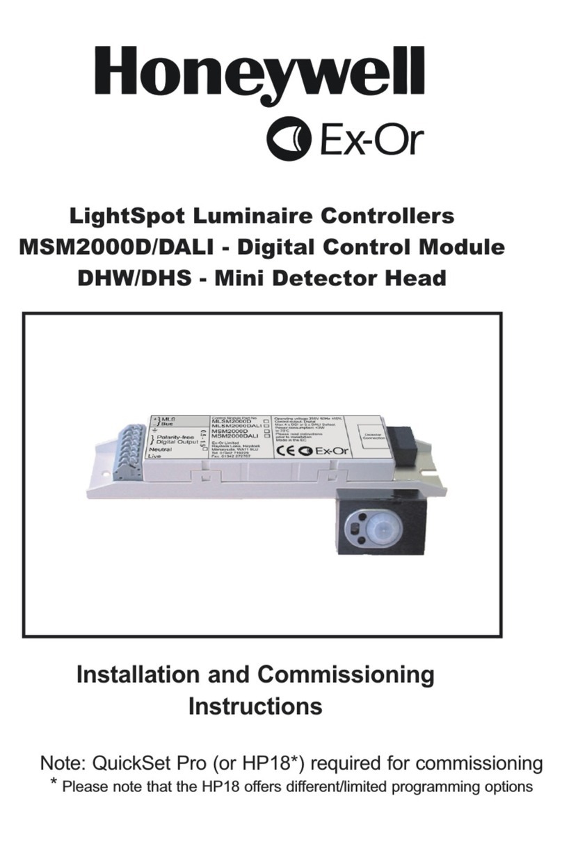
Honeywell
Honeywell Ex-Or MSM2000D Installation and commissioning instructions
Sutron
Sutron XLink 500 Operation & maintenance manual
Linak
Linak TR-EM-273 quick guide
Advantage Controls
Advantage Controls MINI-TROL IF manual
HYDACELECTRONIC
HYDACELECTRONIC HPG 3000-000 operating instructions

