8 EB 8384-1 EN
Design and principle of operation
3 Design and principle of oper-
ation
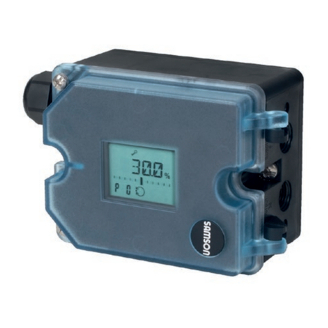
The electropneumatic positioner is mounted
on pneumatic control valves and is used to
assignthevalveposition(controlledvariable
x)tothecontrolsignal(setpointw).Thepo-
sitioner compares the electric control signal
ofacontrolsystemtothetraveloropening
angleofthecontrolvalveandissuesasignal
pressure(outputvariabley)forthepneumat-
ic actuator.
The positioner is designed depending on
whichaccessoriesareselectedeitherfordi-
rectattachmenttoSAMSONType3277Ac-
tuatorsorforattachmenttoactuatorsac-
cordingtoNAMUR(IEC60534-6).
Additionally,acouplingwheelincludedin
theaccessoriesisrequiredtotransferthero-
tarymotionforrotaryactuatorsaccordingto
VDI/VDE3845.
Springlessrotaryactuatorsrequirearevers-
ingamplierincludedintheaccessoriesto
permit the powered operation in either di-
rection.
Thepositionerconsistsofatravelsensorsys-
temproportionaltoresistance,ananalog
i/p converter with a downstream air capaci-
tyboosterandtheelectronicswithmicrocon-
troller.Thepositioneristtedwithtwoad-
justablesoftwarelimitcontactsasstandard
to indicate the valve's end positions.
Thepositionofthevalvestemistransmitted
asaeitheranangleofrotationortravel
overthepick-uplevertothetravelsensor(2)
andsuppliedtoananalogPDcontroller(3).
AnA/Dconverter(4)transmitstheposition
ofthevalvetothemicrocontroller(5).
ThePDcontroller(3)comparesthisactual
positiontothe4to20mADCcontrolsignal
afterithasbeenconvertedbytheA/Dcon-
verter(4).
Incaseofasystemdeviation,theactivation
ofthei/pmodule(6)ischangedsothatthe
actuatorofthecontrolvalve(1)ispressur-
izedorventedaccordinglyoverthedown-
streambooster(7).Thiscausesthevalve
plugtomovetothepositiondeterminedby
the set point.
Thesupplyairissuppliedtotheboosterand
thepressureregulator(8).Anintermediate
owregulator(9)withxedsettingsisused
topurgethepositionerand,atthesame
time,guaranteestrouble-freeoperationof
thebooster.
Theoutputsignalpressuresuppliedbythe
boostercanbelimitedto2.4barbyactivat-
ingtheP9parameter.
Thevolumerestriction(10)isusedtoopti-
mizethepositionerbyadaptingittotheac-
tuatorsize.
Tight-closing function:
Thepneumaticactuatoriscompletelylled
with air or vented as soon as the set point
fallsbelow1%orexceeds99%(seeend
positionfunctioninP10andP11parame-
ters).
