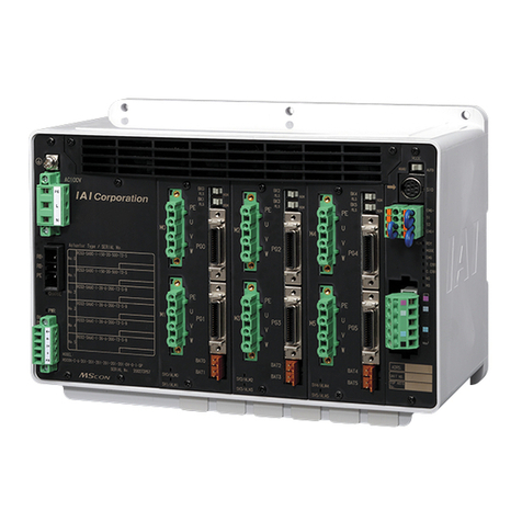
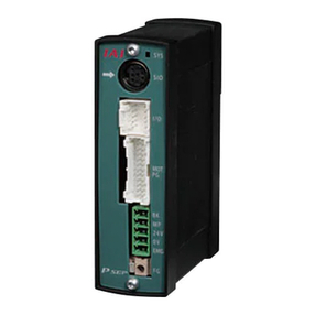
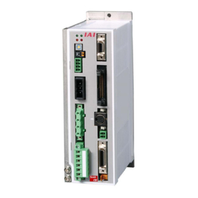
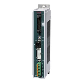
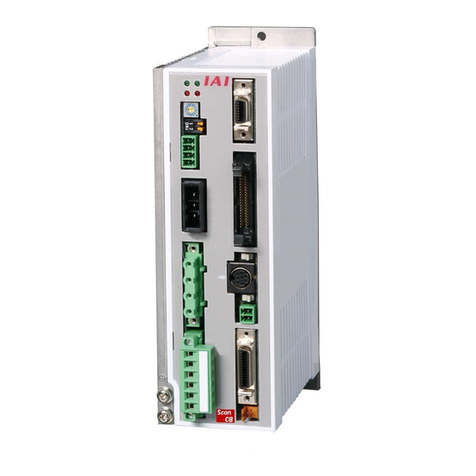
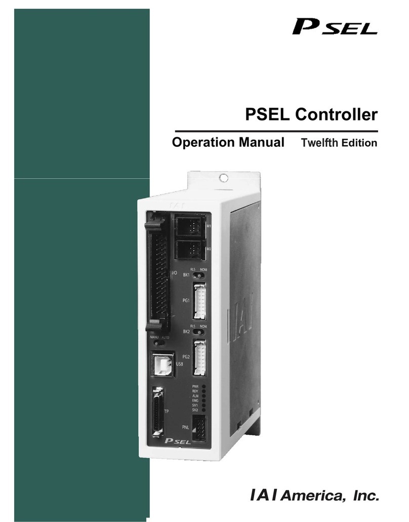
IAI ssel User manual

SSEL
First Step Guide First Edition
Thank you very much for purchasing our product.
Make sure to read the detailed Operation Manual (CD) included with the product
in addition to this First Step Guide to ensure correct use.
Product Check
This product is comprised of the following parts if it is of standard configuration:
1. Parts (The option is excluded.)
No. Part Name Model
1 Controller Refer to “How to understand the Model Name Plate” and
“How to understand the Model No.”
Accessories
2 I I/O Flat cable CB-DS-PIO*** ***indicates the cable length
3 Battery for saving
Absolute Data *1
AB-5
4 AC Power Supply plug MSTB2.5/6-STF-5.0 (Maker : PHOENIX CONTACT)
5 System I/O plug (2 Units) FMC1.5/4-ST-3.5
6 First Step Guide
7 Operation Manual (CD)
8 Safety Guide
*1: It is attached when the unit is absolute type.
2. Teaching Tool (Option)
The personal computer application software or teaching pendant is required for
the operations including program creation and setup such as position setting and
parameter setting with teaching. Use either of them.
No. Part Name Model
1
PC Software
(with RS232C Cable +Emergency Stop Box+ Connector conversion adapter )
IA-101-X-MW-J
2 PC Software (USB Cable with a dummy plug) IA-101-X-USB
3 Teaching pendant SEL-T
4 Teaching pendant (with deadman switch) SEL-TD
5 Wall Hanging Hook specially for SEL-T/TD HK-1
6 Strap specially for SEL-T/TD STR-1
7 Teaching pendant IA-T-X
8 Teaching pendant (with deadman switch) IA-T-XD
9 Panel Unit
*2 PU-1
*2: It is the unit specially for “Status” indication.
3. Operation manuals related to this product, which are contained in the CD.
No. Name Catalog No.
1 SSEL Controller Operation Manual MJ0157
2 PC Software IA-101-X-MW/ IA-101-X-USBMW MJ0154
3 Teaching pendant SEL-T/TD MJ0183
4 Teaching pendant IA-T-X/XD MJ0160
5 DeviceNet Operation Manual MJ0124
6 CC-Link Operation Manual MJ0123
7 ProfiBus-DP Operation Manual MJ0153
4. How to read the model plate
5. How to read the model of the controller
[SSEL]
Basic Specifications
SSEL Specifications
Specification Item Single-Axis Type Double-Axis Type
AC100V Specification 400WMax. Connected
Axis Output AC200V
Specification 800W
AC100V
Specification Single-phase 100V to 115V ± 10%Control Power
Source Voltage AC200V
Specification Single-phase 200V to 230V ± 10%
AC100V
Specification Single-phase 100V to 115V ± 10%Motor Power Source
Voltage AC200V
Specification Single-phase 200V to 230V ± 10%
Power frequency 50/60Hz
Load Current *1 55A (Control) 55A (Driving) 55A (Control) 110A (Driving)
Leakage Current *2 1.0mA or less
Power Capacity for Electro-magnetic Brake Power Unit
*3
(In the case of the actuator with a brake) DC24V ±10% Rated 0.5A MAX 1A DC24V ±10% Rated 1A MAX 2A
Heating Value for Electro-magnetic Brake Power Unit
(In the case of the actuator with a brake) 12W 24W
Momentary Power Interruption Tolerance 50Hz:10msec、60Hz:8msec
Insulation Resistance DC500V 100MΩor more
Insulation Strength AC1500V for 1min. (actuator the time of connection 1000V AC for 1min.)
Axis Control System AC Full –digital Servo
Position detection method Incremental Encoder or Absolute Encoder
For Absolute Data Backup : Manufactured by our company AB-5 (Option)Battery for Backup
For System Memory Backup : Manufactured by our company AB-5 (Option)
Program language Super SEL language
Max. Number of program steps 9999 steps
Max. Number of position 20000 positions
Max. Number of programs 128 programs
Max. Number of multitask programs 8 programs
Data storage device Flash ROM + SRAM Backup (Option)
Data storage method Teaching pendant or PC software
I/O Interface 24 Input Points (Total of Dedicated Input Points + Universal Input Points)
8 Output Points (Total of Dedicated Output Points + Universal Output Points)
PIO Interface Power Supply DC24V ±10% (Externally supplied)
Teaching Port RS232C (Special Protocol) 26-pin Half Pitch I/O Connector (For connecting 1.27mm-pitch PCB Cable Pair
TX20A-26R-D2LT1-A1LHE Manufactured by JAE)
USB Teaching Port for connecting the PC
(Special Protocol)
USB B Connector (XM7B-0442) For connecting the PC
RS232C 15m or lessCommunication
cable length USB 5m or less
System I/O Emergency-stop input, safety gate input
Protective functions Overvoltage, motor over current, motor overload, driver temperature abnormality, and Encoder
abnormality etc.
Drive-source cutoff method Internal Relay
Regenerative Resistance Built-in 20W Power Source (External Expansion Available)
Surrounding air temperature 0 to +40°C
Surrounding humidity 10% to 95%RH (non-condensing)
Surrounding environment There should not be any corrosive gas. In particular, there should not be much dust accumulation.
Surrounding storage temperature -25 to 70 degrees (However, except for battery (option))
Surrounding storage humidity 10% to 95%RH (non-condensing)
Vibration strength
XYZ directions 10 to 57Hz
Pulsating amplitude 0.035mm (continuous) 0.075mm (intermittent)
57 to 150Hz 4.9m/s2(continuous) 9.8m/s2(intermittent)
Environ-
ment
Impact
147mm/s
2
, 11ms Semi-sine wave pulse three times to each of the directions X, Y and Z
Protection class IP20
Cooling method Forced air-cooling
Weight 1380g
External dimensions (Refer to the Item for the External dimensions Dimension)
*1 Rush current at the power connection continues for about 5 msec. Consider the safety
rate at the time when rush current passes. The rush current value varies depending on
the impedance of the power line.
*2 The leaked current value is for the single controller not connected to the actuator.
The leaked current varies depending on the surrounding environment.
When the leakage protective measure is taken, measure the leakage current at the
leakage breaker installation location.
*3 The brake is an instantaneous over excitation brake. Current of max. 1A per axis
passes during 100msec of brake release.
Table 1: Motor Power Unit Capacity and Heating Value
Actuator or
Motor Capacity [W]
Rated Motor
Power Capacity [VA]
Momentary Maximum
Motor Power Capacity
[VA]
Heating Value in
reaching the rated
motor power capacity
[W]
20 26 78 1.6
30 46 138 2.1
60 138 415 3.9
100 234 701 6.1
150 328 984 8.3
200 421 1263 9.1
400 796 2388 19.8
600 1164 3492 27.2
750 1521 4564 29.8
100(Linear Actuator S6SS)
101 303 3.7
100(Linear Actuator S8SS)
159 477 4.1
100(Linear Actuator S8HS)
216 648 3.8
200(Linear Actuator S10SS)
343 1029 5.3
200(Linear Actuator S10HS)
417 1251 5.0
200(Linear Actuator H8SS)
189 567 5.4
200(Linear Actuator H8HS)
379 1137 5.4
200(Linear Actuator L15SS)
189 567 5.4
300(Linear Actuator M19SS)
662 1986 11.6
400(Linear Actuator W21SS)
920 2760 16.7
Table 2: Control Power Unit Capacity and Heating Value
Control Power Capacity [VA] Control Power Unit Heating Value [W]
60 36
[Power Capacity and Heating Value]
Rated Power Capacity [VA] = First Axis Momentary Maximum Motor Power Capacity [VA]*1 + Second Axis
Momentary Maximum Motor Power Capacity [VA]*1 + Control Power Capacity
[VA]*2
Momentary Maximum Power Capacity [VA] = First Axis Momentary Maximum Motor Power Capacity [VA]*3 +
Second Axis Momentary Maximum Motor Power Capacity [VA]*3
+ Control Power Capacity [VA]*1
Heating Value in reaching the Rated Capacity [W] = First Axis Motor Power Unit Heating Value in reaching
the Rated Capacity [W]*4 + Second Axis Motor Power
Unit Heating Value in reaching the Rated Capacity [W]*4
+ Control Power Unit Heating Value [W]*5
*1 Select the Rated Motor Power Capacity from Table 1.
*2 Select the Control Power Capacity from Table 2.
*3 Select the Momentary Maximum Motor Power Capacity from Table 1.
*4 Select the Motor Power Unit Heating Value in reaching the Rated Capacity from Table 1
*5 Select the Control Power Unit Heating Value from Table 2.
SSEL – C -2 -200A -100AB -NP -2 -0
X Y Z [ [ \ ] ^
Model table
[Details of axis 1 to axis 2
X
Series
Y
Controller
Type
Z
Number
of axes
Motor
Output
Encoder
Type Brake Creep Home
Sensor
Synchro-
nization
Desig-
nation
\
Standard
I/O
]
I/O Flat
cable
length
_
Power-
supply
voltage
SSEL
C
(Standard
Type)
1
(1-axis)
2
(2-axis)
30D
(30W for
RCS2)
30R
(30W for
RC)
60
(60W)
100
(100W)
150
(150W)
200
(200W)
300
(300W)
400
(400W)
600
(600W)
750
(750W)
I
(Incre-
mental)
A
(Abso-
lute)
Not
Specified
(w/o
brake)
B
(w/ brake)
Not
Specified
(w/o
creep)
C
(w/
creep)
Not
Specified
(w/o home
sensor)
L
(
Applicable
to Home
Sensor
LS)
Not
Specified
(No
synchro-
nization)
M
(Master-
axis
designation)
S
(Slave-axis
designation)
NP
Standard PIO
Input 24/
Output 8
NPN type
PN
Standard PIO
Input 24/
Output 8
PNP type
DV
DeviceNet
CC
CC-Link
PR
ProfiBus
2 : 2m
(Standard)
3 : 3m
5 : 5m
0 : None
1 :
Single-phase
100V
2 :
Single-phase
200V
MODEL SSEL-C-2-200A-100AB-NP-2-1
SERIAL No. 600061190
MADE IN JAPAN
Model
Serial number

External Dimensions
* Same dimensions are applied to both the single axis and double axis units.
* The above figure shows the condition where the system memory backup battery (option)
and absolute data backup battery have been attached.
Regeneration Resistor Unit (Option) : REU-1, REU-2
Regenerative Resistor Unit: This unit converts the regenerative current brought at the time of
the motor deceleration into heat
[Specification] [External Dimensions]
Item Specification
Dimensions W34mm×H195mm×D126mm
Weight 0.9kg
Built-in regeneration
resistor 220Ω80W
REU-1 Model : CB-ST-REU010 1m
Connection Cable
(Accessories) REU-2 Model : CB-SC-REU010 1m
[Installation Standards]
When it is installed horizontally: Not required
When it is installed vertically:
Connected Actuator Motor
Capacity Total
No. of Connected
Regenerative Resistance
Units
to 200W Not required
to 600W 1
to 800W 2
Installation Environment
Do not use this product in the following environment:
•Location where the surrounding air temperature exceeds the range of 0 to 40°C
•Location where condensation occurs due to abrupt temperature changes
•Location where relative humidity smaller than 30% or larger than 95%RH
•Location exposed to corrosive gases or combustible gases
•Location exposed to significant amount of dust, salt or iron powder
•Location subject to direct vibration or impact
•Location exposed to direct sunlight
•
Location where the product may come in contact with water, oil or chemical droplets
When using the product in any of the locations specified below, provide a
sufficient shield.
•Location subject to electrostatic noise
•Location where high electrical or magnetic field is present
•Location with the mains or power lines passing nearby
Installation and Noise Elimination
1. Noise Elimination Grounding (Frame Ground)
2. Precautions Regarding Wiring Method
•Use a twisted cable for connection to power supply
•Separate the I/O line, communication line and power or driving line to each other.
3. Noise Sources and Elimination
Carry out noise elimination measures for power devices on the
same power path and in the same equipment.
The following are examples of measures to eliminate noise
sources:
①AC solenoid valves, magnet switches and relays
[Measure] Install a noise killer parallel with the coil.
②DC solenoid valves, magnet switches and relays
[Measure] Install a diode parallel with the coil. Use a
DC relay with a built-in diode.
4. Heat Radiation and Installation
Conduct design and manufacture in consideration of the control box size, controller layout
and cooling in such a way that the temperature around the controller will be 40°C or less.
Connection Diagram
*1 When the PC is connected to the controller using the USB cable, it is required to attach
the dummy plug to the controller to short circuit the Safety Gate Signal for the PC
application software and teaching pendant.
*2 It shows an example of PIO interface. In the case of field bus type (DeviceNet, CC-Link or
ProfiBus), the field bus connector (For Device Net, CC-Link or ProfiBus) should be used.
Warning
When the PC is connected to the controller using the USB cable, the emergency stop
box can not be connected. In the case of stop in an emergency, process it in the system.
Wiring for the Power/Emergency Stop Circuit and Brake Forced Release Switch
•SSEL Controller Power Supply Wiring (The Client should prepare it).
*1 Make sure to install the noise filter.
*2 Follow the instructions below for the selection of the circuit breaker.
Breaker Rated Current Value > Power Capacity/ AC Input Voltage
(Refer to “Power Capacity and Heating Value” for Power Capacity.)
•The current might pass through the controller three times more of the rated current at the acceleration. Select one that
does not trip when the above current passes. When it trips, select the breaker with a rated current one rank above.
•Select the breaker that does not trip with the rush current. (Refer to the operating characteristic curve described in the
manufacturer′s catalog.)
•For the rated breaking current, select the current value which can break the current even when a short circuit occurs.
Rated Breaking Current > Short-circuit Current = Primary Power Supply Capacity/Power Voltage
Select the breaking current value for the circuit breaker leaving some margin.
*3 When the leakage breaker is to be installed, it is required to select it with the purpose clarified such as protection from
fire or human body protection.
For the leakage breaker, measure the leakage current at the location where the leakage breaker is installed, and select it.
Use the “applicable to higher harmonics type” leakage breaker.
*4 For the CE marked type, the attachment of the clamp filter for each model shown in the figure, and the connection to
the surge protector, are required.
In addition, for all the cables to be connected to SSEL, arrange them with a length less than 30m.
4.5
100 125
16.6
210.2
177
186
195
16.6
50
4.5
System Memory Backup
Battery
Absolute Data Backup
Battery
34
195
186
175
5
16.6 126
φ5
Controller
Other equipment
Controller
Other equipment Other equipment
Do not share the ground wire with or connect to
other equipment. Ground each controller.
Noise killer
+24V
+24V
0V
0V
Relay coil
R
C
+ -
Relay
coil
100mm or more
50mm
10mm
150mm
or more
Airflow
direction of the wind
Fan
Regeneration
Box
30 30
50mm or more
Earth leakage breaker
Applicable to Higher Harmonics Noise filter(*1)
Recommended : AC100V MC1220
(Maker㧦DENSEI-LAMBDA)
AC200V MC1210
•AC100V
•AC200V
Surge Protector(*4 for CE)
Model : R • A • V-781BWZ-2A
(manufactured by Okaya Denki)
Grounding Cable Thickness Diameter :
1.6mm or more
Power Connector
Encoder Connecto
r
Clamp Filter(*4 for CE)
Model : ZCAT-3035-1330
(manufactured by TDK)
Controller
Earth Terminal
Class D grounding
(Formerly Class-III grounding: Grounding resistance at 100Ω or less)
Annealed copper wire:
Connect a ground wire with a
diameter of 1.6mm or larger.
Attach the earth cable to
the set machine screw
for the main machine.
RDY
LED indication
System I/O
Emergency-stop input, safety gate input
(Emergency Stop Switch Contact on the TP Connector)
Brake Power Unit
Class D grounding
(Formerly Class-III grounding)
(Protective Ground)
Regenerative
Resistor Unit
(Option)
Motor Cable
Encoder Cable
Panel Unit (Option)
Host System (PLC)
PIO
USB Cable
Teaching pendant
(Option)
Personal Computer
EMG
SV2
PWR
ALM
SV1
Dummy Plug
(Option)
*1
*2
AUTO/MANU
Mode
Control AC Power Unit, and
Motor Driving AC Power Unit
First Axis Brake Switch
Second Axis Brake Switch
First Axis
Second Axis
Conversion Cable
(Option)

•Emergency Stop Input Cable Arrangement Example
Shown is an example when two or more controllers on the whole system emergency stop circuit, are stopped in an emergency.
*1 The connection of the teaching pendant is automatically recognized using the controller.
*2 For the CR contacts between EMG “+” and EMG “-”, use DC24V, 0.5A/contact or more.
*3 When the safety category demands a break in the driving source, connect the MC.
Select contact rating for MC based on the current value found in the circuit breaker selection.
Arrange it so that the total does not exceed 0.5A.
If the total exceeds 0.5A, attach an auxiliary relay.
I/O Signals
Program Mode
Input
Pin
No.
Electric
wire
color
Port
No.
Function in Standard
Setting
(in Delivery)
Parameter
No. Parameter Name
Input
Function Set
Value (at the
delivery from
factory)
Input
Function
Set Value
*1
Function
1A BR-1 - I/O power connector + 24V - - - 0 Universal Input
1B RD-1 016 Program No. 1 Selection
(MSB)
251
Input Function Selection 016
9 1 Program Start (BCD) (ON Edge)
Signal
2A OR-1 017 Program No. 2 Selection
(The second bit)
252
Input Function Selection 017
10 2 Program Start (BIN) (ON Edge)
Signal
2B YW-1 018 Program No. 4 Selection
(The third bit)
253
Input Function Selection 018
11 3 Software Reset (Turning ON for
1 second)
3A GN-1 019 Program No. 8 Selection
(The fourth bit)
254
Input Function Selection 019
12 4 Servo ON signal (ON Edge)
3B BL-1 020 Program No. 10 Selection
(The fifth bit)
255
Input Function Selection 020
13 5
Automatic Start Program Start-up
Signal
(ON Edge)
4A PL-1 021 Program No. 20 Selection
(The sixth bit)
256
Input Function Selection 021
14 6 All servo-axes soft interlock
(OFF level)
4B GY-1 022
Program No. 40 Selection
(LSB
•
The seventh bit)
257
Input Function Selection 022
15 7 Operation Pause Cancellation
(ON Edge)
5A WT-1 023 Software Reset 258
Input Function Selection 023
3 8 Pause Signal (OFF level)
5B BK-1 000 Program Start 30
Input Function Selection 000
1 9 Program No. appointment
(MSB)
6A BR-2 001 Universal Input 31
Input Function Selection 001
0 10 Program No. appointment
(The second bit)
6B RD-2 002 Universal Input 32
Input Function Selection 002
0 11 Program No. appointment
(The third bit)
7A OR-2 003 Universal Input 33
Input Function Selection 003
0 12 Program No. appointment
(The fourth bit)
7B YW-2 004 Universal Input 34
Input Function Selection 004
0 13 Program No. appointment
(The fifth bit)
8A GN-2 005 Universal Input 35
Input Function Selection 005
0 14 Program No. appointment
(The sixth bit)
8B BL-2 006 Universal Input 36
Input Function Selection 006
0 15 Program No. appointment
(LSB
•
The seventh bit)
9A PL-2 007 Universal Input 37
Input Function Selection 007
0 16 Error Reset (ON edge)
9B GY-2 008 Universal Input 38
Input Function Selection 008
0 17 Driving Power Interruption
Cancellation Input (ON Edge)
10A WT-2 009 Universal Input 39
Input Function Selection 009
0 18 Hom ing Command Signal for All
Effective Axes (ON Edge)
10B BK-2 010 Universal Input 40
Input Function Selection 010
0 19 All Increment Effective Axes
Homing(ON Edge)
11A BR-3 011 Universal Input 41
Input Function Selection 011
0 20
PC and Teaching Pendant
Servo-Motor Movement Command
Receipt Permission Input
11B RD-3 012 Universal Input 42
Input Function Selection 012
0 21 Rem ote Mode Control Input
12A OR-3 013 Universal Input 43
Input Function Selection 013
0 22 First Axis Brake Forced Release
Input
12B YW-3 014 Universal Input 44
Input Function Selection 014
0 23 Second Axis Brake Forced
Release Input
13A GN-3 015 Universal Input 45
Input Function Selection 015
0
*1 When the input function set values (0 to 23) are set in the I/O parameters 30 to 45 (input function selection 000 to
015) and I/O parameters 251 to 258 (input function selection 016 to 023), the set functions are allocated.
Program Mode
Output
Pin
No.
Electric
wire
color
Port
No.
Function in Standard
Setting
(in Delivery)
Parameter
No. Parameter Name
Output
Function Set
Value (at the
delivery from
factory)
Output
Function
Set Value
*1
Function
13B BL-3 300 Alarm Output 46
Output Function Selection
300 2 0 Universal Input
14A PL-3 301 READY Output 47
Output Function Selection
301 7 1 Error Output at the Operation
Cancellation Level or more(ON)
14B GY-3 302 Universal Output 48
Output Function Selection
302 0 2 Error Output at the Operation
Cancellation Level or more(OFF)
15A WT-3 303 Universal Output 49
Output Function Selection
303 0 3 Error Output at the Operation
Cancellation Level or more+
Emergency-stop Output (ON)
15B BK-3 304 Universal Output 50
Output Function Selection
304 0 4 Error Output at the Operation
Cancellation Level or more+
Emergency-stop Output (OFF)
16A BR-4 305 Universal Output 51
Output Function Selection
305 0 5 READY Output (PIO Trigger
Program Operation Available)
16B RD-4 306 Universal Output 52
Output Function Selection
306 0 6 READY Output (PIO Trigger
Program Operation Available)
and without occurrence of any
error at the operation
cancellation level or more
17A OR-4 307 Universal Output
53
Output Function Selection
307 0 7 READY Output (PIO Trigger
Program Operation Available)
and READY Output (PIO Trigger
Program Operation Available,
and without occurrence of any
error at the cold start level or
more or more level or more
17B YW-4 N I/O power connector 0V - - - 8 Emergency-stop Output(ON)
9
Emergency-stop Output (OFF)
10
AUTO Mode Output
11
Output during the Automatic
Operation
12
Output at the time of “All
Effective Axes Homing (=0)”
13
Output when all the effective
axes homing is completed
14
Output when all the effective axes
home preset coordinates are set
15
System Memory Battery (Option)
Voltage Drop
Warning Output
16
Voltage Drop Warning Output for
the Battery (Option) for
maintaining the Absolute Data
17
Driving Source Interception
(SDN) Notification Output
24
Output during the first axis servo ON
25
Output during the second axis
servo ON
*1 When the output function set values (0 to 17, 24, 25) are set in the I/O parameters 46 to 53 (output function
selection 300 to 307), the set functions are allocated.
The mixed allocation of output function set values 1, 2, 3 and 4 is not available.
The mixed allocation of output function set value 5, 6 and 7 is not available.
Positioner Mode Function description for I/O Signals
Input
Parameter No.25
Signal Abbreviation Signal Name Function Description 123416
PC1 to PC13
PC1 to PC11
Command Position
No. Signal
Input of the position number to m ove (binary input) { { {
Item Change Mode
PC1 to PC16
Position/Item No.
Signal
Input of the No. of item to be moved and position No. (Binary Input) {
DC-S-C1
Interchangeable Mode
PC1 to PC1000
Command Position
No. Signal
Input of the position number to move (BCD input)
(PC1 to 8 : Units Digit, PC10 to 80 : Tens Digit, PC100 to 800 : Hundreds Digit,
PC1000 : Thousands Digit)
{
RES Reset Signal An alarm will be reset when this signal is turned ON. Also, when it is turned ON in the
pause mode (*STP is turned OFF), the remaining movement amount can be cancelled. { { { {
CSTR PTP Strobing Signal
(Start Signal)
The actuator will start to move to the position set by the command position number. { { {
Double Axis
Independent Mode
CSTR1, CSTR2
PTP Strobing Signal
(Start Signal)
The actuator will start to move to the position set by the command position number.
•CSTR1 : First Axis
•CSTR2 : Second Axis
{
HOME
Home Return Signal
The controller will perform home return operation when this signal is turned ON. { {
Double Axis
Independent Mode
HOME1, HOME2
Home Return Signal
The controller will perform home return operation when this signal is turned ON.
•HOME1 : First Axis
•HOME2 : Second Axis
{
SON Servo ON signal The servo remains ON while this signal is ON, or OFF while this signal is OFF. { { {
Double Axis
Independent Mode
SON1, SON2
Servo ON signal The servo remains ON while this signal is ON, or OFF while this signal is OFF.
•SON1 : First Axis
•SON2 : Second Axis
{
PUSH Pressing Signal When the command position No. signal and start signal are input in the Signal ON
mode, the pressing operation is performed. { {
*ST P Pause Signal When this signal turns OFF while the actuator is moving, the actuator will decelerate to stop.
The remaining movement is retained and will resume when the signal is turned ON again. { { {
Double Axis
Independent Mode
*STP1, *STP2
Pause Sign al When this signal turns OFF while the actuator is moving, the actuator will decelerate to stop.
The remaining movement is retained and will resume when the signal is turned ON again.
•*STP1 : First Axis •*STP2 : Second Axis
{
DC-S-C1
Interchangeable Mode
STP
Pause Sign al When this signal turns ON while the actuator is moving, the actuator will decelerate to stop. The
remaining movement is retained and will resume when the signal is turned OFF again. {
*CANC Cancel Signal When this signal turns OFF while the actuator is moving, the actuator will decelerate to
stop. During the stop condition, the remaining movement amount is cancelled, so even
when this signal is turned ON, the movement is not restarted.
{ {
Double Axis
Independent Mode
*CANC1, *CANC2
Cancel Signal When this signal turns OFF while the actuator is moving, the actuator will decelerate to
stop. During the stop condition, the remaining movement amount is cancelled, so even
when this signal is turned ON, the movement is not restarted.
•*CANC1 : First Axis •*CANC2 : Second Axis
{
LINE Interpolation Signal When the double axis unit is used and this signal is turned ON, the two axes perform the
linear interpolation operation { { {
DC-S-C1
I
nterchangeable Mode
CPRES
CPU Reset Signal When this signal is turned ON the controller is re-started up.
{
Teaching Mode
JOG1 +, JOG1 -
JOG2 +, JOG2 -
Jog Signal When the MODE signal is turned ON and the mode is set to Teaching Mode, using the ON
edge detection of this signal, the jog operation is performed in plus or minus direction. When
the OFF edge is detected during the jog operation, it is decelerated and stopped.
•JOG1 +, JOG1 - : First Axis •JOG2 +, JOG2 - : First Axis
{
Teaching Mode
IC001
IC01
IC05
IC1
Inching (Manual
Axis Operation)
Distance Signal
When the MODE signal is turned on and the mode is set to Teaching Mode, specifying
the inching (manual axis operation) distance and entering the jog signal (JOG1+,
JOG1-, JOG2+ or JOG2-), performs the inching (manual axis) operation.
•IC001 : Set the Inching (manual axis operation) Distance to “0.01mm”.
•IC01 : Set the Inching (manual axis operation) Distance to “0.1mm”.
•IC05 : Set the Inching (manual axis operation) Distance to “0.5mm”.
•IC1 : Set the Inching (manual axis operation) Distance to “1mm”.
When two or more inching (manual axis operation) distances (IC001 to IC1) are set, the
inching (manual axis operation) is performed for the total distance.
{
Teaching Mode
CSTR/PWRT
PTP Strobing Signal
(Start Signal)/
Current Position
Write Signal
When the MODE signal is turned OFF and the mode is set to Normal Positioning Mode,
it is used as the start signal.
When the MODE signal is turned ON and the mode is set to Teaching Mode, it is used
as the current position write signal. Specifying the write position and turning ON this
signal for 20msec or more, writes the current position onto the specified position.
{
Teaching Mode
MODE
Teaching Mode
Specifying Signal
When the MODE signal is turned OFF, the mode is set to Normal Positioning Mode.
When the MODE signal is turned OFF, the mode is changed to Teaching Mode.
(When the SERVO is turned ON and jog signal is turned ON, turning ON the MODE
signal starts up the actuator. Be careful.
{
Output
Parameter No.25
Signal Abbreviation Signal Name Function Description 123416
*ALM Controller Alarm
Status Signal
When the controller is turned ON normally, it is turned ON and when the controller is in alarm
mode, it is turned OFF. When the controller is recovered from alarm mode, it is turned ON again.
{ { { {
DC-S-C1
Interchange-
able Mode
ALM
Controller Alarm
Status Signal
When the controller is turned OFF normally, it is turned ON and when the controller is in alarm
mode, it is turned ON. When the controller is recovered from alarm mode, it is turned OFF again.
{
RDY Ready Signal
When the controller initialization is completed normally and the control is enabled, it is turned ON.
{ { { { {
PEND Positioning
Completion Signal
This signal is turned ON when the positioning is completed (the actuator reaches within the positioning range).
When the start signal is turned ON and the movement command is issued, this signal is turned OFF.
Then, after the movement, the start signal is turned OFF and the actuator reaches within the
positioning width, this signal is turned ON. Until the start signal is turned ON, even when the actuator is
out of the positioning width, this signal is not turned ON.
When the start signal continues to be turned ON, even when the actuator reaches within the
positioning width, this signal is not turned ON.
{ { {
Double Axis
Independent Mode
PEND1
PEND2
Positioning
Completion Signal
This signal is turned ON when the positioning is completed (the actuator reaches within the
positioning range).
When the start signal is turned ON and the movement command is issued, this signal is
turned OFF. Then, after the movement, the start signal is turned OFF and the actuator
reaches within the positioning width, this signal is turned ON. Until the start signal is turned
ON, even when the actuator is out of the positioning width, this signal is not turned ON.
When the start signal continues to be turned ON, even when the actuator reaches within the
positioning width, this signal is not turned ON.
•PEND1 : First Axis •PEND2 : Second Axis
{
HEND Homing
Completion Signal
When the power is input, it is in the OFF mode. This signal will turn ON when home
return has been completed. It is turned ON when the homing command is issued. { { {
Double Axis
Independent Mode
HEND1, HEND2
Homing
Completion Signal
When the power is input, it is in the OFF mode. This signal will turn ON when home
return has been completed. It is turned ON when the homing command is issued.
•HEND1 : First Axis •HEND2 : Second Axis
{
SVON
Servo ON Status Signal
This signal will remain ON while the servo is ON. { { {
Double Axis
Independent Mode
SVON1, SVON2
Servo ON Status Signal
This signal will remain ON while the servo is ON.
•SVON1 : First Axis •SVON2 : Second Axis {
PSED Pressing
Completion Signal
In the pressing operation, when the operation is completed, this is turned ON. When the swing error does
not occur (when the pressing operation is completed), the turning-off condition is continued.
{ {
SSER*1 System Battery
Error Signal
When the system memory battery (option) voltage drops, it is turned ON. { { { {
ABER*1
Battery for the Absolut
e
Data Maintenance
When the absolute data preservation battery (option) voltage drops, it is turned ON. { { { {
Teaching Mode
PEND/WEND
Positioning
Completion
Signal/Writing
Completion Signal
In the normal positioning mode (MODE signal is turned OFF), it is used as the positioning
completion signal.
This signal will turn ON when the target position has been reached after movement and the
actuator has entered the in-position range.
In the teaching mode (MODE signal is turned ON), it is used as the writing completion signal. At
the moment when the current position data writing is completed, it is turned ON.
{
Teaching Mode
TCMD
Operation Mode
Status Signal
It is turned OFF in the Normal Positioning Mode and turned ON in the Teaching Mode. {
*1 Turn ON the lamp, etc., with this signal. Use this signal for the alarm for battery change.
Motor Power
Unit
Main CPU
Connection
detection circuit
SSEL Controller
External EMG
switch
(*1)
S1
+24V
S2
EMG+
EMG-
ENB+
ENB-
Safety gate
L1
L2
L1C
L2C Control Power
Unit
(It is turned ON when the
open/close door is closed.)
EMG Switch for the
Teaching Pendant
Motor Power
Breaker Relay
Main CPU
Emergency Stop Circuit
SSEL Controller
+24V 0V
(*2)
MC1
MC2
MCn
CR
CR
Safety gate
S1
+24V
S2
CR
CR
EMG+
EMG-
ENB+
ENB-
L1
L2
L1C
L2C
L1
S1
S2
EMG+
EMG-
Safety gate
Safety gate
L2
L1C
L2C
L1
L2
L1C
L2C
EMG-
EMG+
S2
S1
Second Unit
MC1
CR
MC2
MCn
External EMG
reset switch
External EMG
switch
(*2)
(*2)
(*3)
(*1)
(*3)
(*3)
(*3)
(*3)
Motor Power
Unit
Control Power
Unit
(It is turned ON
when the open/close
door is closed.)
EMG Switch for the
Teaching Pendant
Motor Power Breaker Relay
(It is turned ON
when the open/close
door is closed.)
(It is turned ON
when the open/close
door is closed.)
n Unit
(*3)

Positioner Mode
Mode Standard
Mode Item Change
Mode
Double Axis
Independent
Mode
Teaching
Mode ゙
DS-S-C1
Interchangeable
Mode
Other Parameter No. 25 1 2 3 4 16
Pin No. Electric
wire color Category
1A BR-1 +24V P24
1B RD-1 PC10 PC10 PC7 JOG1- PC1000
2A OR-1 PC11 PC11 PC8 JOG2+ -
2B YW-1 PC12 PC12 PC9 JOG2- -
3A GN-1 PC13 PC13 PC10 IC001 -
3B BL-1 - PC14 PC11 IC01 -
4A PL-1 - PC15 PC12 IC05 -
4B GY-1 - PC16 PC13 IC1 -
5A WT-1 RES RES RES RES CPRES
5B BK-1 CSTR CSTR CSTR1 CSTR/PWRT CSTR
6A BR-2 HOME HOME HOME1 SON STP
6B RD-2 SON SON SON1 *STP CANC
7A OR-2 PUSH PUSH *STP1 PC1 LINE
7B YW-2 *STP *STP *CANC1 PC2 PC1
8A GN-2 *CANC *CANC CSTR2 PC3 PC2
8B BL-2 LINE LINE HOME2 PC4 PC4
9A PL-2 PC1 PC1 SON2 PC5 PC8
9B GY-2 PC2 PC2 *STP2 PC6 PC10
10A WT-2 PC3 PC3 *CANC2 PC7 PC20
10B BK-2 PC4 PC4 PC1 PC8 PC40
11A BR-3 PC5 PC5 PC2 PC9 PC80
11B RD-3 PC6 PC6 PC3 PC10 PC100
12A OR-3 PC7 PC7 PC4 PC11 PC200
12B YW-3 PC8 PC8 PC5 MODE PC400
13A GN-3
Input
PC9 PC9 PC6 JOG1+ PC800
13B BL-3 *ALM *ALM *ALM *ALM ALM
14A PL-3 RDY RDY RDY RDY RDY
14B GY-3 PEND PEND PEND1 PEND/WEND PEND
15A WT-3 HEND HEND HEND1 HEND -
15B BK-3 SVON SVON SVON1 SVON -
16A BR-4 PSED PSED PEND2 TCMD -
16B RD-4 SSER SSER HEND2 SSER SSER
17A OR-4
Output
ABER ABER SVON2 ABER ABER
17B YW-4 0V N
I/O Flat cable
Model CB-DS-PIO□□□
Input section Output section
Item Specification Item Specification
Input voltage DC24V ± 10% Load voltage DC24V
Input current 7mA Peak load electric current 100mA/1 point 400mA/8 points *1
NPN ON Voltage: MIN. DC16.0V
OFF Voltage: MAX. DC5.0V Leakage Current MAX. 0.1mA
Specification
ON/OFF
Voltage
PNP ON Voltage: MIN. DC8.0V
OFF Voltage: MAX. DC19.0V
*1 The total of lead current reaches max. 400mA every
8 ports from output port No. 300.
NPN
Controller
Internal
Power Source
P24
Input Terminal
680Ω
3.3kΩ
External
Power
Source
DC24V
±10%
N
Load
P24
Controller
Internal
Power Source
Output Terminal
External
Power
Source
DC24V
±10%
Surge Absorber
Surge Absorber
Surge Absorber
PNP
680Ω
3.3kΩ
N
Controller
Internal
Power Source
Input Terminal
External
Power
Source
DC24V
±10%
P24
NLoad
Controller
Internal
Power Source
Output Terminal
External
Power
Source
DC24V
±10%
Surge Absorber
Surge Absorber
Surge Absorber
The I/O circuit is an equivalent circuit expressing the logic.
NPN type PNP type
Starting Procedures
When using this product for the first time, make sure to avoid mistakes and incorrect wiring by
referring to the procedure below.
Troubleshooting
The following alarm displays are frequently generated at the start-up operation. Process it referring to the following description.
Deal with each of them referring to the following table.
Status display
Code Status contents Cause and Remedy
LED
Personal
Computer
TB
Panel Unit
(Option)
EMG During
emergency-stop
It is not an alarm.
•It is generated when the emergency stop switch in the
teaching pendant or the personal computer application
software is not cancelled. In such case, cancel it.
•It is generated when the personal computer cable is not
connected to the emergency stop box.
•Check the emergency stop circuit.
○
enb Safety gate remains
opening
Deadman switch
OFF
It is not an alarm.
•It is generated when the system I/O ENB signal is opened.
Check the ENB signal. (It is generated when the safety gate
is open. Close the safety gate.)
•It is generated when the AUTO/MANU switch has been set to
“MANU” and the personal computer or the teaching pendant
is not connected. Connect the personal computer or the
teaching pendant or set the AUTO/MANU switch to “AUTO”.
•When the actuator is to be started up, hold the deadman
switch on the teaching pendant to turn it on.
ACF AC Power
Interruption
Momentary Power
Failure
Power Voltage Drop
It is generated when the power voltage is not supplied. It will be
generated, for example, in the case that the AC100V is supplied
to the controller with AC200V specified. Check the power
supply.
CA1 Absolute Data
Backup Battery
Voltage Error
It is caused when the battery is not attached or battery voltage
drops.
In the case of the actuator for the single-axis robots or
Cartesian robots with the absolute data specifications, it is
generated when the power is connected for the first time.
Perform the absolute reset.
○
D12 Encoder
Disconnection Error
It is generated when the cable is broken or the encode cable is
not connected to the controller. Check the wiring.
○
D19 Encoder Reception
Time Out
It is generated when the encoder is broken down, the cable is
broken or the encoder cable is not connected to the controller.
Check the wiring.
○
E69
E6C
24V I/O Error
DO output current
error
It is generated when the +24V power for I/O is not supplied.
Check the power supply.
(How to start up the controller without connecting the I/O 24V
power)
Set both the I/O parameter No. 10 to “0”.
○
D5□Field Bus Error It is generated when the field bus link connection is not
established.
Check the link cable connection, I/O parameter and PLC
parameter settings.
(How to start up the controller without connecting the field bus)
Set both the I/O parameter No. 10 to “0”.
○
IAI America Inc.
Head Office: 2690W 237th Street Torrance, CA 90505
TEL (310) 891-6015 FAX (310) 891-0815
Chicago Office: 1261 Hamilton Parkway Itasca, IL 60143
TEL (630) 467-9900 FAX (630) 467-9912
Atlanta Office: 1220-E Kennestone Circle,Marrietta,GA 30066
TEL (678) 354-9470 FAX (678) 354-9471
website: www.intelligentactuator.com
IAI Industrieroboter GmbH
Ober der Röth 4, D-65824 Schwalbach am Taunus, Germany
TEL 06196-88950 FAX 06196-889524
* Enter the cable length (L) in□□□ (up to 10m)
Example) 080=8m
No. color Wirings No. color Wirings
1A BR-1 9B GY-2
1B RD-2 10A W T-2
2A OR-1 10B BK-2
2B YW-1 11A BR-3
3A GN-1 11B RD-3
3B BL-1 12A OR-3
4A PL-1 12B YW-3
4B GY-1 13A GN-3
5A WT-1 13B BL-3
5B BK-1 14A PL-3
6A BR-1 14B GY-3
6B RD-2 15A W T-3
7A OR-2 15B BK-3
7B YW-2 16A BR-4
8A GN-1 16B RD-4
8B BL-2 17A OR-4
9A PL-2
Flat cable
(Press
welding)
17B YW-4
Flat cable
(Press
welding)
Set-up for operation is completed. Perform the system operation adjustment.
Catalogue No.: ME0209-1
A
2m
Flat cable AWG28
(34 conductors)
1A1B
17A17B
No
connector
1A
1B
2A
13A
13B
14A
17A
17B
0V +24V
Pin No.
Load
A
→
↓Yes
Perform the absolute reset.
Confirm the alarm description in the window
of the personal computer or teaching
pendant, and deal with it.
(Refer to the “Treatments in Error Condition”)
In the case that it has been installed vertically, repeating the
servo turning ON/OFF, might lower the unit slightly due to the
weight of the unit itself. In such case, take care so that your
hand is not caught or the work is not damaged.
* The homing operation for the absolute type is not required.
Set-up for operation is completed. Set the position and start the program.
A
PIO Pattern Settings
Set the Other Parameter No. 25.
Setting Range 1: Standard Mode
2: Item Change Mode
3: Double-Axis Independent Mode
4: Teaching Mode
16: DS-S-C1 Interchange Mode
(Refer to the Instruction Manual for the details).
Set the safety speed.
When the machine is delivered from the factory, the safety speed is
set to 250mm/s using the Parameter No. 33 common to all axes.
Change it if necessary.
Connect the motor cable.
•To ensure safety, it is recommended that safety speed be enabled during initial movements.
•When the unit is installed vertically and the brake release switch is set to “RLS” side, the unit might
drop due to its own weight. In such case, take care not to catch your hand or damage the handle.
No→
→
No→
→
↓Yes
↓
↓Yes ↓No
↓Yes
↓No
↓Yes
↓
↓
↓
No→
↓Yes
↓Yes
↓
↓
↓
No→
↓Yes
↓
→No→No→
↓Yes
No→
↓Yes
↓Yes
No→
Contact the sales shop.
Point Check Item
•Have you perform the frame grounding and protective grounding processing.
•Has the noise countermeasure been taken?
Power Supply and Alarm Check
Connect the personal computer or teaching
pendant, set the AUTO/MANU switch to the
[MANU] side and inject the power.
Check Item 1
Is the LED indicator
[EMG] turned off on the
front panel?
When the USB port is used, is the
dummy plug inserted to connect?
Insert the dummy plug to connect.
Check Item 1
Are the LED Indications “PWR” and
“RDY” turned ON on the front panel?
Is the LED Indication “ALM” turned OFF?
Is the actuator for Absolute?
Confirm the emergency stop switch box
connection.
Confirm that the emergency stop switch
has been cancelled.
Installation and Wiring
Install the controller and actuator and perform wiring according
to the instruction manual and the contents in this book.
Check of Packed Items
Are there all the delivered items?
PIO Pattern Settings
When the other parameter No. 25 is not set to
“0”, set it to “0”.
(When the machine is delivered from the factory,
it is set to “0”
)
.
Parameter Setting
Set the parameters including I/O parameter with
the personal computer or teaching pendant
operation.
Servo ON
Turn ON the servo motor with the personal
computer or teaching pendant operation.
Connect the motor cable.
When the alarm is output, deal with it after
confirming the alarm description, using the
personal computer or teaching pendant
operation.
Homing Execution
Home the actuator with personal computer or
teaching pendant operation.
Check of Safety Circuit
Check that the emergency stop circuit (or motor drive power
cutoff circuit) operates normally to turn off the servo.
Check the emergency stop circuit.
Confirming the operation of the actuator
Confirm that the full stroke operation is performed without any
trouble with the jog operation.
Has the motor cable connected?
Servo ON
Turn ON the servo motor with the personal
computer or teaching pendant operation.
Has the motor cable
connected?
Confirm the alarm description in the window of the
personal computer or teaching pendant, and deal with it.
(Refer to the “Treatments in Error Condition”)
Check the emergency stop circuit.
Check of Safety Circuit
Check that the emergency stop circuit (or motor drive-power
cutoff circuit) operates normally to turn off the servo.
Target Position Setting
Set a target position in the “Position” field for each position in the position table.
When carrying out direct teaching, perform home return operation first.
When the unit is equipped with the brake, move it after setting the brake release switch to “RLS” side.
Confirming the operation of the actuator
Confirm that the full stroke operation is performed without any trouble with the jog operation.
←In the case of Program Mode:
In the case of Positioner Mode:
Check Item
Are the LED Indications
“SV1” and “SV2” for the
turned ON axes turned ON?
In the case that it has been installed vertically, repeating the
servo turning ON/OFF, might lower the unit slightly due to the
weight of the unit itself. In such case, take care so that your
hand is not caught or the work is not damaged.
Check Item
Are the LED Indications
“SV1” and “SV2” for the
turned ON axes turned ON?
1A
1B
2A
13A
13B
14A
17A
17B
0V+24V
Pin No.
Load
Other manuals for ssel
3
Other IAI Controllers manuals

IAI
IAI PCON-CB series User manual

IAI
IAI ROBO Cylinder RCP2 Series User manual

IAI
IAI X-SEL-J*-1-CC0 series User manual

IAI
IAI ROBO Cylinder RCP5-SA4C User manual

IAI
IAI MCON-C User manual

IAI
IAI PCON-CB series User manual

IAI
IAI PSEL User manual

IAI
IAI EC-RR6*AH series User manual

IAI
IAI RCP4 User manual

IAI
IAI RCD Series User manual