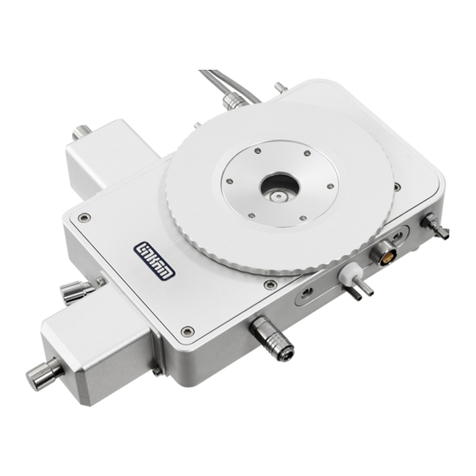
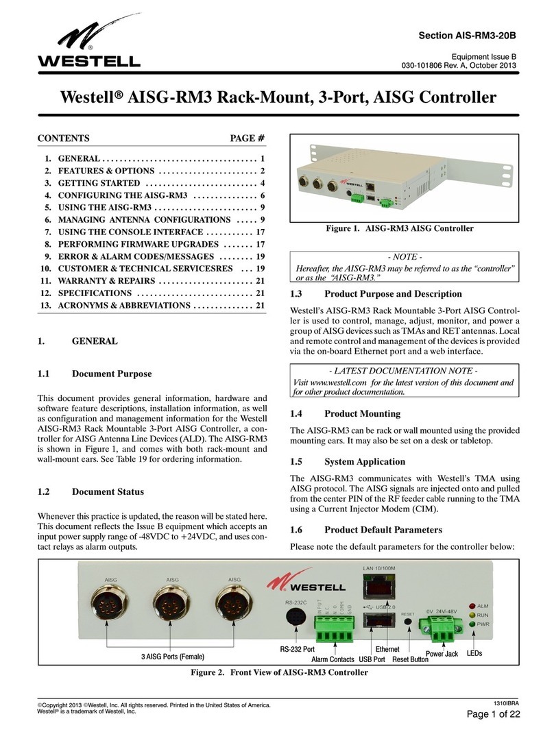
Linkam Scientific Instruments LTSE420-P User manual

LTSE420-P
Temperature Controlled Probe Stage
USER GUIDE
Linkam Scientific Instruments

2
Contents
Before Setting Up your Equipment…………………………………………………………………………….………..3
Important Notice...................................................................................................................4
Warranty..............................................................................................................................4
Technical Support.................................................................................................................4
Equipment Maintenance........................................................................................................4
Handling Liquid Nitrogen.......................................................................................................4
Feedback..............................................................................................................................4
Safety Precautions................................................................................................................5
Symbol Reference.....................................................................................................5
Introduction..........................................................................................................................6
LTSE420-P Stage Specification...................................................................................6
LTSE420-P System................................................................................................................6
Stage Anatomy.....................................................................................................................7
Lid Assembly.............................................................................................................7
Stage and Heater Assembly…………………………………………………………..…………....………….7
Stage Connectors Assembly…………………….…….…………………...…………………………………..7
LTSE420-PL8 Stage Assembly.....................................................................................8
LTSE420-PB4 Stage Assembly....................................................................................8
Mounting Stage to Microscope with Dovetail Substage.............................................................9
Setting up the Condenser......................................................................................................9
Setting up ECP Water Circulator Pump..................................................................................10
Connecting the Instruments.................................................................................................11
T95 System Controller Cable Connections..................................................................11
LNP95 Cooling Pump Connection..............................................................................11
Remove Transit Screws................................................................................11
Back Panel Cable Connection........................................................................11
LTSE420-PB4 BNC Wire Connection……………………………………………………………….………………….12
Remove the Probe………………………………………………………………………………………………..12
BNC Wire Connection……………………….………………………………………………………….……….12
LTSE420-PL8 Lemo Wire Connection………………………………………………………………………………….14
Remove the Probe………………………………………………………………………………………………..14
Internal Electrical Contact Wiring……………………….………………………………………………….14
Probe Wire Connection……………………………………………………………………………………….…………….16
Adjusting the Probe……………………..…………………………………………………………………………………..16
Probe orientation……………………………………………….………….…………………………………....16
Adjusting the length of the needle…………………………………………………………………..…….17
Bend the tip of the needle………………………………………………………………………….………...17
Change the angle of the needle………………………………………………………………….………….17
Sample Preparation………………………………………………………………………………………………………….18
Cooling Connections............................................................................................................20
Purging Procedure...............................................................................................................21
Use LinkPad to set the LNP95 to Manual Mode..........................................................25
Filling the Liquid Nitrogen Dewar..............................................................................21
Purging the Stage Method 1.....................................................................................22
Purging the Stage Method 2.....................................................................................23
Appendix............................................................................................................................24
Window Assembly...............................................................................................................24
Lid Window Assembly..............................................................................................24
Bottom Window Assembly........................................................................................24
Troubleshooting..................................................................................................................25
Contact Details....................................................................................................................26

3
Before Setting Up Your Equipment
Please register your products by going to www.linkam.co.uk and click on the
product/software registration button.
You will need to register your equipment with us to:
Activate your warranty and technical support
Access the online setup videos
Permanently unlock the LINK software (if purchased)
If you have purchased LINK software, please install the software first. This process
will guide to register all of your products.
See LINK manual for further installation instructions.

4
Important Notice
Please check that your Linkam equipment has not been damaged during transit. If there is any evidence of
external damage DO NOT SWITCH ON ANY ELECTRICAL ITEMS.
Contact LINKAM SCIENTIFIC or their appointed distributor immediately. Your warranty may be im-
paired if Linkam is not informed of any transport damage within 7 working days of delivery.
NO attempt should be made to repair or modify the equipment in any way, as there are no user replaceable
parts.
No attempt should be made to open the case except by qualified personnel as hazardous voltages are pre-
sent.
In order to use this equipment successfully, please take time to read this manual all the way through before
using it.
Warranty
This equipment has a warranty against defects in material and workmanship for a period of 12 months.
Linkam will either repair or replace products that prove to be defective. For warranty service or repair,
this product must be returned to Linkam or a designated service facility.
The warranty shall not apply to defects resulting from interfacing, unauthorized modification or misuse,
operation outside of the environmental specifications for the product, or improper site preparation or
maintenance.
Technical Support
Any technical questions or queries should be addressed to the Technical Support Department at the ad-
dress shown on the back of this manual.
Equipment Maintenance
Use a small quantity of isopropyl alcohol with a soft cloth and gently wipe the surface. To clean the stage,
use isopropyl alcohol (IPA) and cotton swabs. Take great care not to touch the platinum temperature
sensor protruding from the side of the heating element. The sensor is very fragile.
Handling Liquid Nitrogen
To cool samples below room temperature a LNP95 liquid nitrogen pump is required. Please refer to your
health and safety manual for instructions on how to handle liquid nitrogen safely. The Dewar supplied
with the LNP95 has a safety release valve built into the siphon assembly. Always use in a well ventilated
room.
Feedback
Your feedback will be greatly appreciated, please go to www.linkam.co.uk to fill in the Feedback form.

5
Safety Precautions
1) Safety Precautions
1) Read this guide before using the equipment. Save these instructions for later use.
2) Follow all warnings and instructions which may be placed on the stage.
3) Never use the equipment if any cables have been damaged. Do not allow any heavy objects to rest
on the cables. Never lay the cables on the floor.
4) Do not obstruct any ventilation holes. Do not attempt to insert anything into these openings. Pro
vide adequate ventilation of at least 75mm all around the equipment.
5) Do not expose the equipment to water. If for any reason it gets wet then unplug it from the mains
and contact Linkam Scientific Technical Support.
6) The equipment is not intended to be used outdoors.
7) If any problems occur then turn all Linkam equipment off and contact Linkam Scientific
Technical Support.
8) Do not remove any covers from the equipment, any servicing should be carried out by qualified
service personnel.
Symbol References
Caution:
This safety symbol is on the back panel of the equipment and warns:-
The user must not make or remove any connections while the unit is powered on.
To avoid electric shock do not remove the cover. Refer servicing to qualified service personnel.
Caution:
This warning symbol indicates that the surface labelled with this symbol may be hot.

6
Introduction
Thank you for purchasing the LTSE420-P Probe
Heating and Freezing stage system. Please take
the time to read through the manual as it will help
you to make the most out of the equipment.
LTSE420-P Stage Specifications
Stage:
Maximum temperature: 420°C
Minimum temperature: -196°C with LNP95
Maximum heating rate: 30°C/min
Objective Lens WD: 8.2mm
Condenser lens WD: 12.5mm
Heating surface area: 43 x 53mm
Aperture hole: 2.5mm
Probe:
Maximum voltage: 300V AC
Maximum ampere: 4A
LTSE420-P System
There are two versions of the LTSE420-P stage:
1. LTS420-PL8
2. LTS420-PB4
The LTSE420-PL8 stage is supplied with 2x 4 pin
Lemo connectors and the LTSE420-PB4 stage is
supplied with 4x BNC connectors. Each stage
type is supplied with 4 Probes. The LTSE420-
PL8 can be upgraded to a maximum of 8 Probes.
Each system consists of a LTSE420-P stage, a
T95-LinkPad System Controller with LINK soft-
ware and optional LNP95 liquid nitrogen cooling
pump system for cooling to –196°C.
LINK-DV (digital video) and Linkssy32-AV
(analogue video) video capture software can be
added as an option to control from PC.
Note: please first install the software on the PC
and activate LINK within 10 days.
The LTSE420-P stage is mounted onto the micro-
scope by using either specific stage clamps, an
adaptor plate or by simply placing on the XY
table of the microscope, using double sided adhe-
sive tape.
LTS420-P System with LNP95

7
Stage Anatomy
Lid Assembly
Swing the Stage Lid (1) to open the Stage.
1. Stage Lid
2. Lid Insert
3. Viewing Window
4. Hinge
5. Holes for Tube Clip Holder
or window removal tool
Stage and Heater Assembly
6. Stage Chamber
7. Heating / cooling block (43x53mm)
8. Heating element wire
9. Aperture hole (2.5mm)
10. Liquid nitrogen cooling tube
11. PT100 platinum temperature sensor
12. Stage Chamber
13. Lid rubber sealing o-ring seal
Stage Connectors Assembly
14. Bypass Stage body water cooling connector
15. Stainless steel cooling tube for liquid nitrogen
16. Lemo connector for Stage Lead
17. Stage body water cooling connector
18. Gas purge valve
123
Swing Stage Lid to open
5
4
14
15
16
17
18
8
9
7
11
12
6
10
13

8
LTSE420-PL8 Stage Assembly
1. Probe
2. Electrical contact
3. Metal base plate
4. 4 Pins Lemo connector
LTSE420-PB4 Stage Assembly
4. Probe
5. BNC Connector
6. Metal base plate
1
2
4
4
5
4
5
3
6

9
Mounting Stage to Microscope
with Dovetail Substage
The following description is for mounting the
stage on to microscopes which have a circular
dovetail substage assembly (1).
Attach the curved stage clamps (part no. 9548) to
the base of the stage using the supplied hex
screws and the outer most holes in the base plate.
Adjust the two positioning screws (2) so that
approximately 5mm of thread is exposed on the
inside edge of the clamp. This will roughly posi-
tion the stage in the centre of the dovetail.
If you are using the stage in transmission, place
the stage onto the dovetail, then focus a 10X
objective lens on the aperture of the heating ele-
ment. Using the two positioning screws (2)
ensure that the aperture is in the centre of the field
of view and lock the stage in place by tightening
the Locking Thumbscrew (3).
For other types of microscope substage, refer to
the diagram included with the stage adaptor.
Setting up the Condenser
If you are using the stage in transmission, place a
small sample on a microscope slide and place
onto the surface of the microscope slide. Use a
10X lens to focus on the sample. Now close
down the microscope field diaphragm and adjust
the condenser focus so that the edges of the dia-
phragm are in focus. Now use the condenser
positioning screws to centre the condenser in your
field of view. Open the diaphragm so that it just
fills the field of view.
For more information about Koehler illumination
see the extremely informative ‘Microscopy Pri-
mer’ on the Molecular Expressions website.
http://micro.magnet.fsu.edu/primer/
index.html
9542 curved clamps set
2
2
3
Linkam Imaging Station
with dovetail substage
1

10
Setting up ECP Water Circulator
Pump
If you have purchased the ECP with your
LTSE420-P stage, read the following to set up the
ECP (1). Refer to the ECP manual for more
details.
When heating the stage above 300°C for a pro-
long period of time, the metal body of the stage
can get quite hot. The ECP is used to cool the
metal casing. Connect the tubing as shown in the
opposite picture.
Note: If you have an LNP95 Liquid Nitrogen
Cooling system, the tubing from the Dewar must
not be connected to the LTSE420-P stage when
heating above 300°C. The thin black capillary
tube will melt inside the heater and damage it.
1
OutletBypass cooling
Inlet

11
Connecting the Instruments
T95 System Controller
Cable Connections
For more details on the T95 System Controller
please refer to the T95 System Controller manual.
Connect the Stage Cable to the Lemo Connector
on the stage and connect the other end to the
Stage Connection Socket (1).
LNP95 Cooling Pump Connection
If your system is supplied with a LNP95 Liquid
Nitrogen Cooling Pump System, setup the LNP95
as described below.
Remove Transit Screws
Before using the LNP95 remove the 4 transit
screws, marked by small yellow labels (2), from
the base of the LNP95. Transit screws shown by
arrows in the adjacent image. These screws hold
the pumps in place for shipping.
Keep the screws safe by screwing them into the
holes on the back panel as shown by the arrows.
The screws must be replaced back into the transit
holes on the base, when shipping back to Linkam
for service or repair.
Back Panel Cable Connection
Connect the Instrument Bus Cable (3) between
the LNP95 and T95 as shown.
Note: either of the purple coloured Instrument
Bus Sockets on the LNP95 can be used.
LNP95 MUST BE SWITCHED ON BE-
FORE T95 SYSTEM CONTROLLER.
T95
LNP95
3
T95 back panel
1
2

12
LTSE420-PB4 BNC
Wire Connection
Only read the following section if you have the
LTS420-PB4 stage with the BNC connector.
Remove the Probe
The LTSE420-P is supplied with 4 tungsten gold
plated tip Probes inside the stage. The probe
assembly (1) has a magnetic base and is held in
place by the metal plate (2) inside the stage cham-
ber .
Grip the probe and lift up to remove the probe
from the stage.
Note: the Probe has a very sharp needle tip, be
careful not to hurt yourself with it.
BNC Wire Connection
Remove the BNC connector (3) by using a hex
key (2.5mm) to remove the 4x hex screws holding
it to the LTSE420-PB4 stage.
Cut a piece of the supplied yellow wire and strip
8mm of the insulation.
Fold the bare wire in half.
Solder the wire to the end of the BNC Socket as
shown.
Reconnect the BNC connector to the stage. Make
sure the yellow wire is fed through the hole in the
stage.
1
2
3

13
Wire your BNC cable to the supplied BNC plug.
Plug the BNC plug into the BNC Socket.

14
LTSE420-PL8 Lemo
Wire Connection
Only read the following section if you have the
LTS420-PL8 stage supplied with the Lemo con-
nectors.
Remove the Probe
The LTSE420-PL8 is supplied with 4 tungsten
gold plated tip Probes inside the stage. The probe
assembly (1) has a magnetic base and is held in
place by the metal plate (2) inside the stage cham-
ber .
Grip the probe and lift up to remove the probe
from the stage.
Note: the Probe has a very sharp needle tip, be
careful not to hurt yourself with it.
Internal Electrical Contact Wiring
Each of the 8x internal electrical contact assembly
(3) has a self-closing spring loaded pin (4).
Using a finger tip push down the pin to open the
electrical contact (5)
Cut a piece of the supplied yellow wire and strip
5mm of the insulation. Twist the end of the ex-
posed wires to hold them together.
Insert the wire into the open electrical contact.
Release the finger and the action of the spring
will hold the wire in place.
1
2
4
3
5

15
The 8x internal electrical contacts are wired to 2x
external 4 pin Lemo conectors (1)
Wire cables to your supplied Lemo connector.
To reconnect the Lemo, line up the red dot on the
Lemo plug (2) to the red tab on the Lemo socket
(3) and push the Lemo firmly into place.
Note: remove the Lemo plug by holding it firmly
and pulling it gently away from the Stage.
32
1

16
Probe Wire Connection
Cut the other end of the yellow wire to the desired
length and strip 5mm of the insulation.
The first step is to ensure that the probe assembly
holding screws (1 and 2) are securely tightened in
place.
Next, loosen the wire holder screw (3) and wrap
the striped end of the wire around it.
Once the wire has been wrapped around it and is
sitting in the groove, tighten up the screw until
secure.
Adjusting the Probe
Probe orientation:
The probe has a magnetic base (3) and can be
placed in any orientation inside the LTSE420-P
stage using the metal base plate.
Note: be extra careful when placing the Probe
near to the PT100 platinum temperature sensor
(4), the PT100 is very fragile and can be easily be
damaged.
3
3
2
1

17
Adjust the length of the needle:
Pull end of the needle to the desired length and
use a wire cutter to cut the needle shorter.
Bend the tip of the needle:
Use a pair of flat pliers to bend the tip of the
needle.
Note: this action can only be done once. Tung-
sten metal is brittle and bending it again will
break the needle.
Change the angle of the needle:
Use the supplied M1 Hex Key (1) to shorten or
lengthen the grub screw (2) to change the angle of
the needle.
Note: the probe is spring loaded and makes better
contact with the sample if the needle is adjusted a
fraction lower than the sample.
1
2

18
Sample Preparation
For accurate results it is most important that the
surface of the block is extremely clean, since air
gaps between the heating block and the sample
will result in temperature errors.
Use a soft cloth and IPA (iso-propyl alcohol) to
clean. Do not use excessive force when cleaning
the heating element as this will bend the heater
assembly.
Do not place the Probe inside the stage without a
sample or a glass sample window. The block can
get scratched easily especially by the sharp needle
of the Probe. This can cause a ridge to form
which prevents the sample from sitting flat on the
block with the resulting air gap causing signifi-
cant temperature errors.
Ensure that the sample is as small and as flat as
possible, heat flow into or out of the sample is
affected by the amount of sample area in contact
with the temperature controlled silver block.
If your sample is inert e.g. a silicon wafer, this
type of sample can be placed directly on top of
the silver block.
If your sample melts or reacts with the nickel
plated bock when heating/freezing, place a W22G
(22 x 0.17mm) glass sample window on top of the
silver block first and then place your sample on
top.

19
Or place a standard microscope glass slide (26
x76mm) on top first and then place your sample
on top of the microscope glass slide.
Arrange the Probes around your sample as re-
quired by your experiment.
Note: make sure the yellow wires are not touching
the silver block. The wire will melt when the
block is hot.
Note: make sure the yellow wires are inside the
stage and is not in the way when the lid is closed.

20
Cooling Connections
These connections need only be made if the
experiments are to be carried out below room
temperature.
The Dewar siphon (1) is the thick white foam
tubing and is attached to the liquid nitrogen Dew-
ar. The thin black capillary tube inside the white
foam tube must be inserted into the liquid nitro-
gen cooling connector on the stage.
The white tubing slides on to the outside of the
connector. Twist the siphon whilst sliding it on
and push until it comes to a stop. It does not need
to go all the way to the base of the connector.
The thicker silicon tube from the LNP95 cooling
pump ends in a white PTFE connector (2), this is
pushed over the end of the other stainless steel
connector as seen in the image.
The short tube branching from the side of this
white connector is the Gas Purging Tube (3).
There is a valve opening Insert connector (4)
inserted into the end of this tube. During the
purging procedure, insert this connector into the
Gas Purge Valve (5) on the side of the stage to
open it.
The Gas Purge Valve (5) is opened when the Gas
Insert (6) is pushed firmly into the connector, a
“click” is heard when the two parts are connected
properly. To remove the Gas Insert, push the
outer sleeve of Gas Purge Valve toward the stage
and the Gas Insert (6) should drop out.
There is a second Gas Purge Valve on the oppo-
site side of the stage to allow the gas to leave the
stage. A Gas Insert must also be inserted into this
Gas Purge Valve (7) when purging.
The smaller tube from the outlet on the LNP95
should be placed in position on the top of the lid
using the Tube Clip Holder (8). This tube blows
warm recycled nitrogen gas across the lid window
to prevent condensation on the viewing window
surface.
1
2
34
7
5
6
8
Table of contents
Other Linkam Scientific Instruments Controllers manuals
