Aurora TAVIS TAV-10 User manual

i
USERS GUIDE
www.auroramm.com
Manual Number: 201115 | Firmware Rev: 0.0.6 or Higher
TAV-10, TAV-15, TAV-21

ii
USERS GUIDE
www.auroramm.com
SAFETY INSTRUCTIONS
Please review the following safety precautions. If this is the first time using this model, then read this manual before
installing or using the product. If the product is not functioning properly, please contact your local dealer or Aurora for
further instructions.
The lightning symbol in the triangle is used to alert you to the presence of dangerous voltage inside the product that may
be sufficient to constitute a risk of electric shock to anyone opening the case. It is also used to indicate improper installation
or handling of the product that could damage the electrical system in the product or in other equipment attached to the
product
The exclamation point in the triangle is used to alert you to important operating and maintenance instructions. Failure to
follow these instructions could result in injury to you or damage to the product.
Be careful with electricity:
Power outlet: To prevent electric shock, be sure the electrical plug used on the product power cord matches the
electrical outlet used to supply power to the Aurora product. Use only the power adapter and power connection cables
designed for this unit.
Power cord: Be sure the power cord is routed so that it will not be stepped on or pinched by heavy items.
Lightning: For protection from lightning or when the product is left unattended for a long period, disconnect it from the
power source.
Also follow these precautions:
Ventilation: Do not block the ventilation slots if applicable on the product or place any heavy object on top of it.
Blocking the air flow could cause damage. Arrange components so that air can flow freely. Ensure that there is adequate
ventilation if the product is placed in a stand or cabinet. Put the product in a properly ventilated area, away from direct
sunlight or any source of heat.
Overheating: Avoid stacking the Aurora product on top of a hot component such as a power amplifier.
Risk of Fire: Do not place unit on top of any easily combustible material, such as carpet or fabric.
Proper Connections: Be sure all cables and equipment are connected to the unit as described in this manual.
Object Entry: To avoid electric shock, never stick anything in the slots on the case or remove the cover.
Water Exposure: To reduce the risk of fire or electric shock, do not expose to rain or moisture.
Cleaning: Do not use liquid or aerosol cleaners to clean this unit. Always unplug the power to the device before
cleaning.
ESD: Handle this unit with proper ESD care. Failure to do so can result in failure.
FCC
This device complies with Part 15 of the FCC Rules. Operation is subject to the following two conditions:
(1)This device may not cause harmful interference.
(2)This device must accept any interference received, including interference that may cause undesired operation.
IMPORTANT NOTE:
Note: This equipment has been tested and found to comply with the limits for a Class B digital device, pursuant to part
15 of the FCC Rules. These limits are designed to provide reasonable protection against harmful interference in a
residential installation. This equipment generates, uses and can radiate radio frequency energy and, if not installed and
used in accordance with the instructions, may cause harmful interference to radio communications. However, there is

iii
USERS GUIDE
www.auroramm.com
no guarantee that interference will not occur in a particular installation. If this equipment does cause harmful
interference to radio or television reception, which can be determined by turning the equipment off and on, the user is
encouraged to try to correct the interference by one or more of the following measures:
—Reorient or relocate the receiving antenna.
—Increase the separation between the equipment and receiver.
—Connect the equipment into an outlet on a circuit different from that to which the receiver is connected.
—Consult the dealer or an experienced radio/TV technician for help.
FCC Radiation Exposure Statement:
This equipment complies with FCC radiation exposure limits set forth for an uncontrolled environment. This equipment
should be installed and operated with minimum distance 20cm between the radiator & your body.
Trademarks
All trademarks in this document are the properties of their respective owners.

iv
USERS GUIDE
www.auroramm.com
TABLE OF CONTENTS
PACKAGE CONTENTS................................................................................................................................1
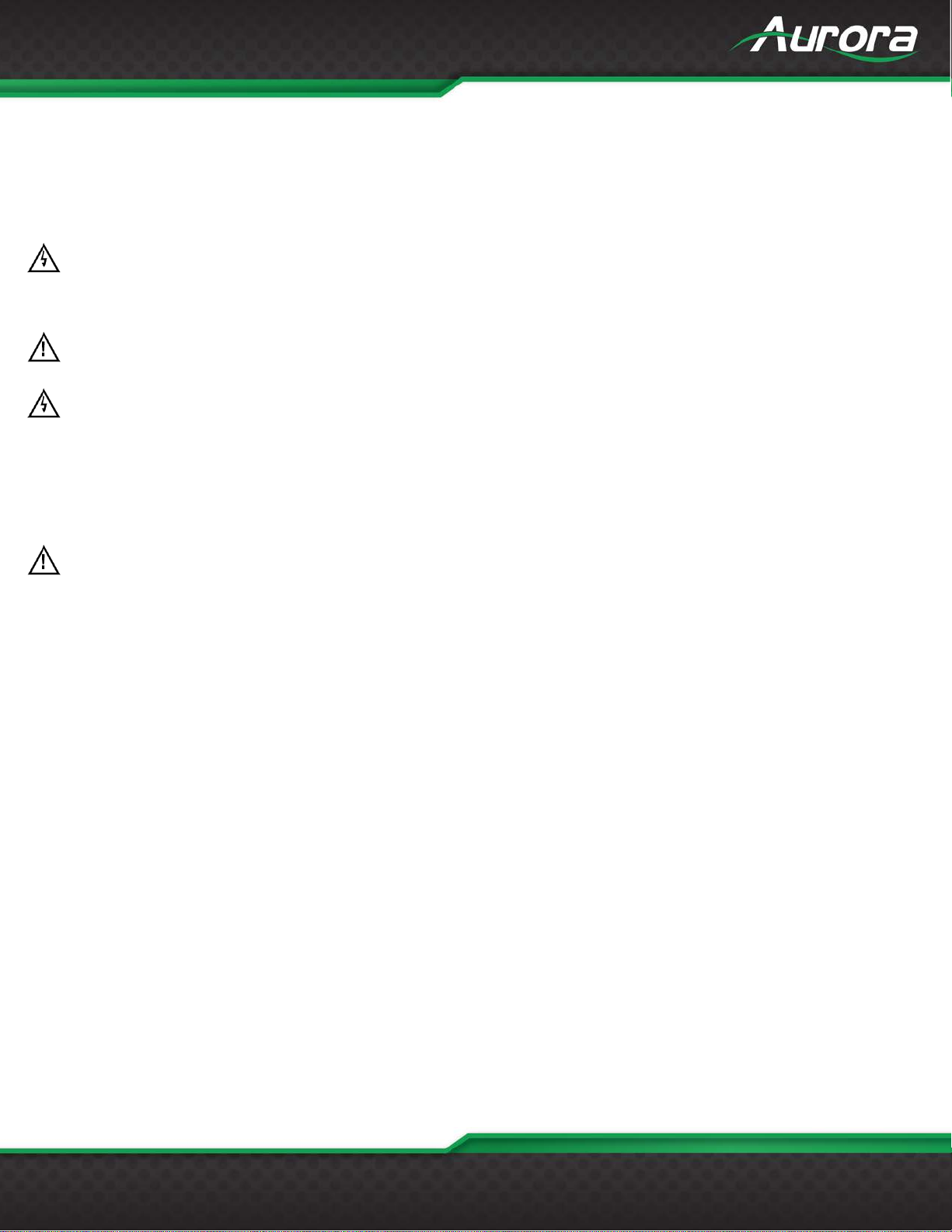
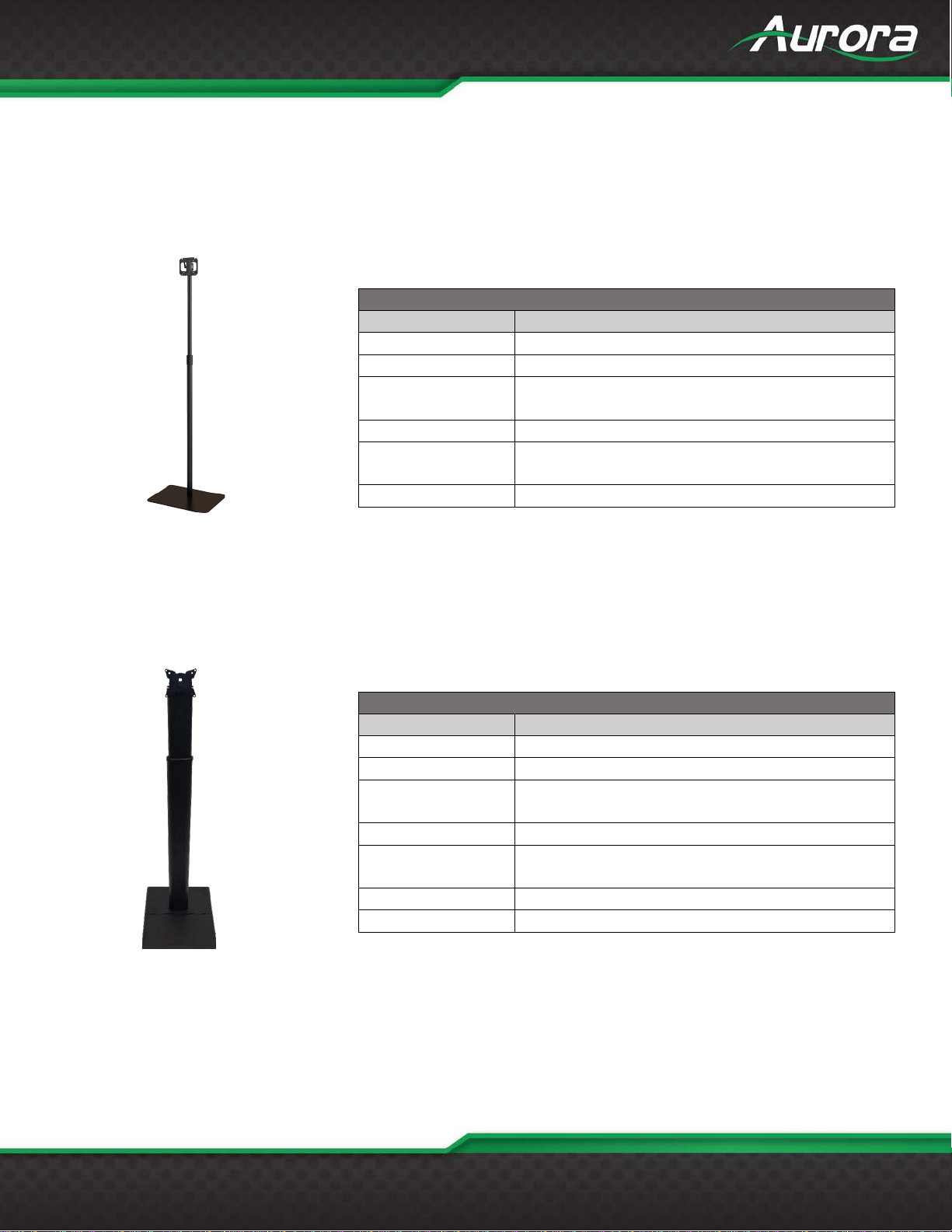
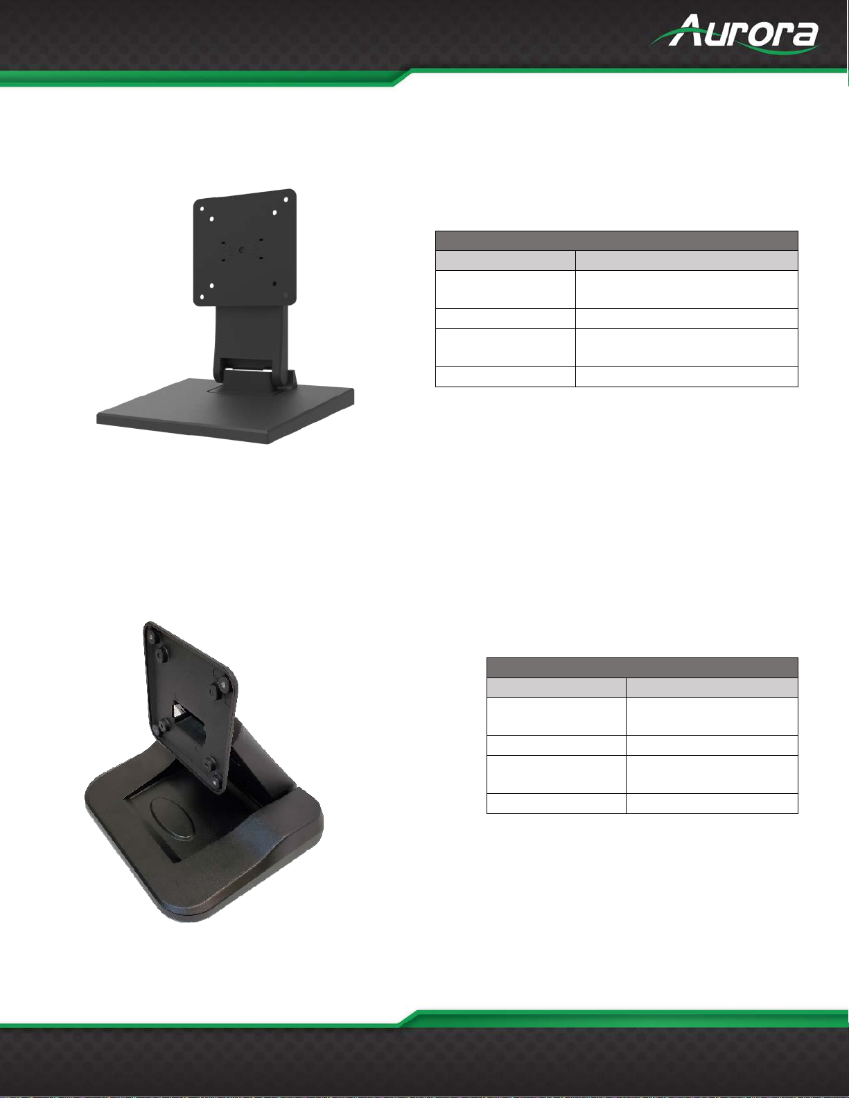
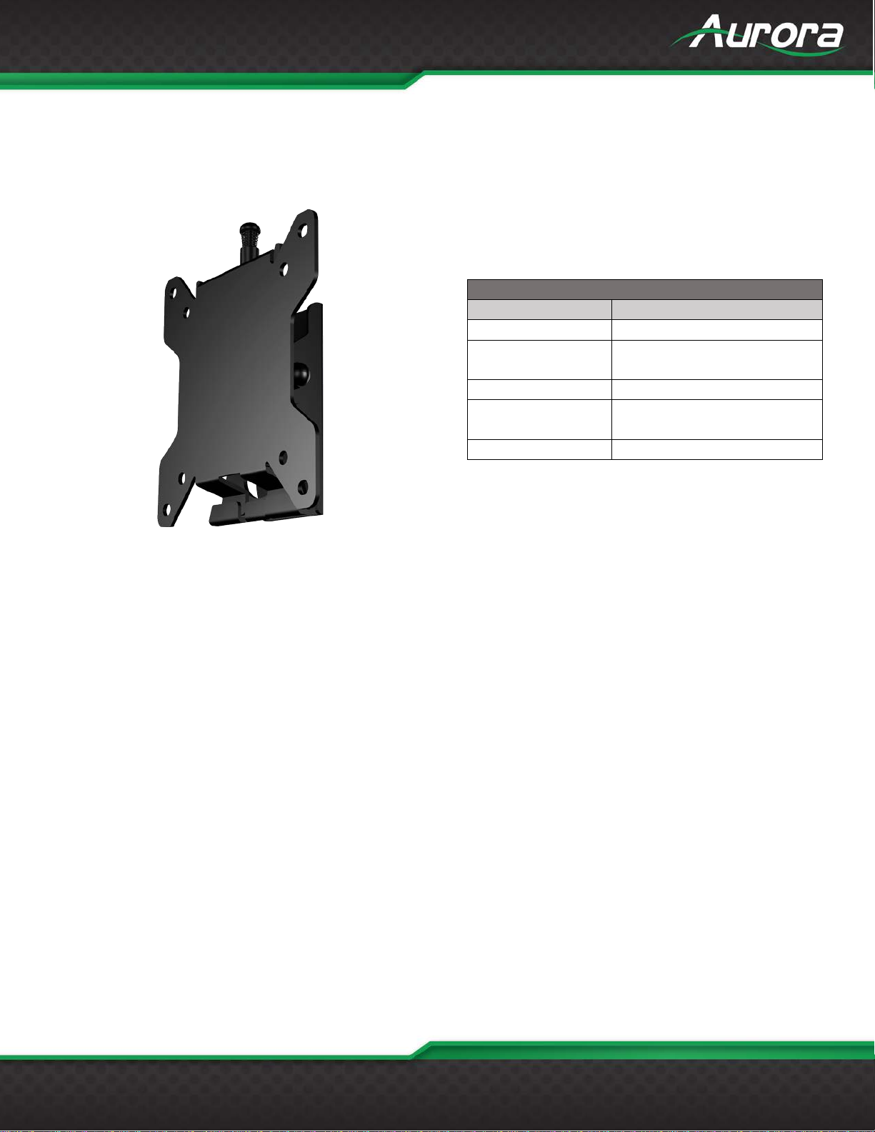
RECOMMENDED WALL MOUNTS .............................................................................................................2
INTRODUCTION...........................................................................................................................................6
About ......................................................................................................................................................6
Documentation........................................................................................................................................6
Features..................................................................................................................................................7
Technical Specifications .........................................................................................................................8
Advanced Optional Features..................................................................................................................8
TAVIS Front.............................................................................................................................................9
TAVIS Bottom Ports..............................................................................................................................10
TAVIS Rear...........................................................................................................................................11
UNDERSTANDING THE BASICS..............................................................................................................12
Powering on the Device........................................................................................................................12
First time setupup wizard......................................................................................................................12
Understanding the Display ...................................................................................................................15
Accessing the Settings .........................................................................................................................15
HARDWARE INSTALLATION....................................................................................................................16
Device Placement.................................................................................................................................16
Software Setup.....................................................................................................................................18
SOFTWARE SETTINGS.............................................................................................................................19
TAVIS Settings......................................................................................................................................19
Admin Settings......................................................................................................................................21
Network Settings...................................................................................................................................22
Device Settings.....................................................................................................................................23
System Settings....................................................................................................................................24
Exiting the Menu...................................................................................................................................26
Display Modes......................................................................................................................................27
Remote Operation ................................................................................................................................31
Additional Capabilities ..........................................................................................................................32
ADDITIONAL SOFTWARE.........................................................................................................................33
ReAX™ Core Studio.............................................................................................................................33
Using ReAX™ Core Studio ..................................................................................................................35

v
USERS GUIDE
www.auroramm.com
TAVIS Central .......................................................................................................................................37
CONNECTOR PIN DEFINITION.................................................................................................................40
HDMI.....................................................................................................................................................40
USB.......................................................................................................................................................40
CAT5e/6/6A ..........................................................................................................................................40
APPENDIX 1...............................................................................................................................................41
Frequently Asked Questions.................................................................................................................41
Troubleshooting....................................................................................................................................46
Firmware Update..................................................................................................................................46
Technical Specifications .......................................................................................................................47
Warranty ...............................................................................................................................................50

1
USERS GUIDE
www.auroramm.com
PACKAGE CONTENTS
Please make sure the following items are included within your package. Contact your dealer if any items are missing or
damaged.
TAVIS Thermal AudioVisual Integrated Solution - TAV Series
TAV-10
1 QTY 10” TAVIS Thermal AudioVisual Integrated Solution tablet
1 QTY Power Adaptor
1 QTY Power Cable
TAV-15
1 QTY 15.6” TAVIS Thermal AudioVisual Integrated Solution tablet
1 QTY Power Adaptor
1 QTY Power Cable
TAV-21
1 QTY 21.5” TAVIS Thermal AudioVisual Integrated Solution tablet
1 QTY Power Adaptor
1 QTY Power Cable
Note: Go to www.auroramm.com for the latest manual and firmware.

2
USERS GUIDE
www.auroramm.com
RECOMMENDED WALL MOUNTS
APS-1
The APS-1 is an adjustable pole stand for the TAVIS Thermal AudioVisual Integrated Solution Series. The 25 pound
weight base assures its stability. The height range is ~45” – 76” and the angle is adjustable.
APS-2-B (Black) & APS-2-W (White)
The APS-2 is an adjustable VESA pole stand with base compartment. The base compartment is designed to hold up to
a 50000mA hour battery for portable applications. There are optional locking caster wheels available for easy roll-around
use (APS-2-CS).
APS-1
Specifications
Measurements
Height
45”-76”
Angle
Adjustable Tilt
Base Dimensions
[L x W x H]
15” x 19” x 0.25”
38.1cm x 48.26cm x 0.635cm
Weight
26lbs (11.793kg)
VESA Mount
75mm x 75mm
100mm x 100mm
Package Contents
Monitor Column, Column Base, Auxilary Screws
APS-2
Specifications
Measurements
Height
45”-76” (965mm – 1650mm)
Angle
Adjustable Tilt
Base Dimensions
[L x W x H]
14.71” x 13.189” x 1.87”
360mm x 335mm x 47.5mm
Weight
30.5lbs (13.835kg)
VESA Mount
75mm x 75mm
100mm x 100mm
Package Contents
Monitor Column, Column Base, Auxilary Screws
Options
APS-2-CS Locking Caster Wheel Kit

3
USERS GUIDE
www.auroramm.com
DTM-3
The DTM-3 is an adjustable desktop mount for the TAVIS Thermal AudioVisual Integrated Solution Series. It can tilt up
or down, making alignment with a person easy. The DTM-3 is suggested as the desk mount for the TAV-10. (The TAV-
15 will also fit, if you need the lowest profile mount.)
DTM-4-B (Black) & DTM-4-W (White)
The DTM-4 is an adjustable desktop mount for the TAVIS Thermal AudioVisual Integrated Solution Series. It can tilt up
or down, making alignment with a person easy. The DTM-4 is suggested as the desk mount for the TAV-10.
DTM-3
Specifications
Measurements
Base Dimensions
[L x W x H]
8” x 8.5” x 9”
20.32cm x 21.59cm x 22.86cm
Weight
2.806lbs (1.273kg)
VESA Mount
75mm x 75mm
100mm x 100mm
Package Contents
DTM-3 Desktop Mount
DTM-4
Specifications
Measurements
Base Dimensions
[L x W x H]
9.45” x 8.27” x 7.01”
24cm x 21cm x 17.8cm
Weight
4.094lbs (1.86kg)
VESA Mount
75mm x 75mm
100mm x 100mm
Package Contents
DTM-4 Desktop Mount

4
USERS GUIDE
www.auroramm.com
WMT-1
The WMT-1 is a wall mount for the TAVIS Thermal AudioVisual Integrated Solution Series. It can tilt up or down.
WMT-1
Specifications
Measurements
Angle]
Adjustable Tilt
Base Dimensions
[L x W x H]
5” x 4.5” x 1.45”
12.7cm x 11.43cm x 3.68cm
Weight
0.907lbs (411.4g)
VESA Mount
75mm x 75mm
100mm x 100mm
Package Contents
WMT-1 Wall Mount

6
USERS GUIDE
www.auroramm.com
INTRODUCTION
About
The TAVIS (Thermal AudioVisual Integrated Solution) Tablet Series is an all-in-one infrared temperature sensing tablet
comprised of three sizes (10.1”, 15.6”, & 21.5”). To ensure that people entering a location are not presenting a high
temperature, the TAVIS tablets will provide alerts when a person is running a high temperature within 1 second from up to
5 feet (1.5 meter) away. The system uses advanced algorithm for detecting and calculating heat signatures even the tear
ducts (Canthus) at close distances, achieving more accurate readings with IR technology. The highly accurate 80x64 sensor
measures with a tolerance of +/- 0.3 degrees Celsius (+/- 0.5 degrees Fahrenheit).
Mask detection has become an important part of screening. TAVIS uses advanced AI algorithms to quickly identify if a
person is wearing masking.
TAVIS + ReAX™ offers state-of-the-art digital signage capabilities, security features and control systems integration.
Beyond the thermal detection features, TAVIS + ReAX™ can be used in conjunction with QR codes to check in employees,
confirm identification with gestures, connect to a secure database, provide on-screen instructions and much more. With
ReAX™, you can import your own HTML, CSS, or JavaScript code to design TAVIS’s interface. Even with no coding
experience, ReAX Core Studio™ allows the average user to create his or her desired interface using the studio’s intuitive
tools.
To compliment the TAVIS hardware, Aurora has developed a Server software TAVIS Central which allows full monitoring of
all TAVIS units at a facility. Reporting, alerts, statistics, firmware updating, remote monitoring, and even recording capabilities
are available.
Documentation
Aurora provides many documents to support the TAVIS Thermal AudioVisual Integrated Solution Series and accessories.
Below is a list of the available documents that can be found on the download tab of the TAVIS Thermal AudioVisual
Integrated Solution products or the customer portal.
TAVIS TAV Series Info Sheet
TAV-10 Dimensions, TAV-15 Dimensions & TAV-21 Dimensions
TAVIS Quick Reference Guide
TAVIS Firmware Update Guide

7
USERS GUIDE
www.auroramm.com
Features
TAVIS – A Generation Ahead
10.1”, 15.6”, 21.5”, & Box version (TAV-10, TAV-15,
TAV-21)
Scan Distance: Up to 5’ (1.5m)
2 Person Forehead Scanning
Scan speed: Less than 1 Second
Canthus (Tear Duct) Eye Detection (Highest Possible
Accuracy from 12”away)
Mask Detection
Eye Wear Detection
Anti-Spoofing (Prevents Objects Being Utilized to
Simulate Pass or Fail)
Future Firmware Upgrades & Options
Facial Recognition (Localized or Centralized)
4K Digital Signage Capabilities
Age, Gender, & Ethnicity Prediction
QR Code Detection
Gesture Responses
Streaming Video for Security
Email Alerts
RGB Color Indicator Bar
Portrait or Landscape Mounting
Available in Black or White
Made in the USA
Embedded ReAX Control for Automation & Integration
with Third-Party Devices and Access Systems
Customizable Web Pages (Mobile too)
Patent Pending
TAV-10-B
TAV-10-W

8
USERS GUIDE
www.auroramm.com
Technical Specifications
Scan Distance: (.3m to 1.5m) 1’ to 5’
Accuracy: +/- 0.3°C (+/- 0.5°F)
80x64 Resolution (5x More than 32x32)
Android 9 and Linux (Q1)
6 Core Processor, 4GB RAM, 32GB Flash
HDMI Output for Remote Viewing
Stereo Mics with Audio Processing
WiFi and 1G Ethernet
PoE, PoE+, PoE++ (10.1”, 15.6”, 21.5”)
VESA Mounting
Advanced Optional Features
Criminal Database Crosschecking
Centralized Server Software
Centralized Facial Recognition
Two Way Audio Video Support Desk (Q1)
Voice Recognition (Q1)
4G Data Connection
TAV-21-B
TAV-15-B

9
USERS GUIDE
www.auroramm.com
TAVIS Front
Front Display Monitor
10.1” 1280 x 800 Resolution (TAV-10)
15.6” 1920 x 1080 Resolution (TAV-15)
21.5” 1920 x 1080 Resolution (TAV-21)
For black add -B to part number
For white add -W to part number (Note: TAV-15 & TAV-21 have 100pc minimum and lead-time for white)
Thermal Sensor Camera Module (TAV-A80)
80 x 64 Heiman Sensor IR Longwave +/- 0.3° C (+/- 0.5° F) Accuracy
2 MP Binocular Camera (RGB & IR)
Night Vision with IR Camera and IR LEDs
Stereo Audio Microphone
Audio Digital Signal Processing IC for Noise Cancelation, Echo Cancelation, Feedback Suppression, & Automatic Gain
Control.
Programable Light Bar (Red, Green, Blue, Brightness)

10
USERS GUIDE
www.auroramm.com
TAVIS Bottom Ports
Inputs / Outputs
12v DC Input
USB Type C
3.5mm Audio Line L/R Out
HDMI 2.0 Output
SD Card Slot
SIM Card Slot (4G Option)
USB 3.0
USB 2.0
1G LAN PoE

11
USERS GUIDE
www.auroramm.com
TAVIS Rear
Thermal Sensor Module Mounting
The TAVIS devices are very flexible allowing use in portrait or landscape depending on the application. There are 2 mounting
locations, one at the top and one on the side. When TAVIS is shipped it is mounted on the top for Landscape viewing. To
move there are 2 screws and 2 cables that must be removed and moved to the other location.
Bottom Port Cover
The TAVIS has a cover for the bottom ports which is held on with 2 screws. This allows protection from tampering and
makes the unit have a cleaner look and feel.
VESA Mounting
TAV-10: 75mm x 75mm
TAV-15 & TAV-21: 100mm x 100mm
Button
TAV-10 has a rear standby button.

12
USERS GUIDE
www.auroramm.com
UNDERSTANDING THE BASICS
Powering on the Device
TAVIS will begin operating once it is connected to a power source. Please allow up to fifteen minutes warmup prior to use
for the most accurate results. If it is your first-time powering on the device, please follow the setup wizard on screen to
configure your settings and calibrate your device.
First time setupup wizard
The first time you run the TAVIS panel a setup wizard will appear upon boot to make setting up the unit easier.

13
USERS GUIDE
www.auroramm.com

14
USERS GUIDE
www.auroramm.com

15
USERS GUIDE
www.auroramm.com
Understanding the Display
TAVIS has two primary interfaces: simple and detailed. By default, the user will see scanning instructions, the camera’s
video on screen, and a notification to whether or not they have passed or failed their temperature reading. The settings and
additional information may be accessed by clicking the “gear” or “i” icon in the bottom right corner. The detailed view includes
everything from the simple view, as well as an active thermal image, the user’s temperature, and whether or not their face
and their face mask are detected. For more details, please see the “default interface” section of this manual.
Accessing the Settings
After you have followed the setup wizard, the settings will be available by clicking the “gear” icon in the lower right-hand
corner on either the simple interface or the detailed interface. You will be prompted to enter a password, which by default
is “12345”.
SIMPLE INTERFACE DETAILED INTERFACE
This manual suits for next models
2
Table of contents
Other Aurora Measuring Instrument manuals
Popular Measuring Instrument manuals by other brands

Bridge Technologies
Bridge Technologies VB60 QAM Initial setup guide

Peak
Peak Atlas DCA Pro user guide

Stahl
Stahl 8455 operating instructions

Elforlight
Elforlight Spot Series manual

PCB Piezotronics
PCB Piezotronics 350C03 Installation and operating manual

PCB Piezotronics
PCB Piezotronics IMI SENSORS ICP 66212APZ1 Installation and operating manual