Austin Motor Company A40 Somerset Sedan User guide

(
AUSTIN)
A40
MODELS
THE
AUSTIN
MODELS
RUNNING AND
MAINTENANCE
THE AUSTIN MOTQR COMPANY THE AUSTIN MOTOR COMPAN'
LTD. (ENGLAND) (CANADA) LTD.
27-29 WEST 57th STREET 1393 YONGE STREET
NEW YORK 19, N.Y. TORONTO, ONTARIO
U
.S. CENTRAL PARTS DIVISION
27-29 WEST 57th STREET, NEW YORK 19, N.Y.
'UBLICATION NO. Al881 JUNE 1952

THE AUSTIN 'A40' MAINTENANCE INSTRUCTIONS
INTRODUCTION
THlS owners' handbook gives the running instructions
necessary to ensure satisfactory operation of the 'A40'
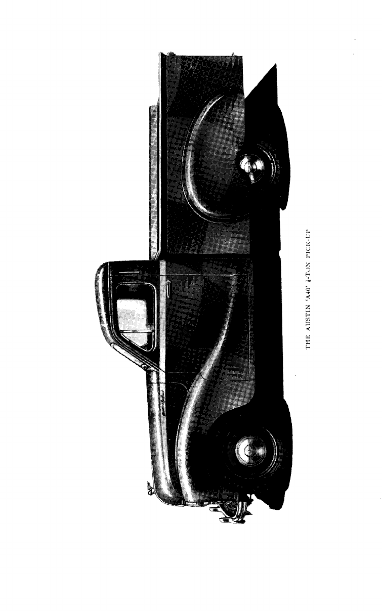
Somerset Sedan, Sports Convertible, Countryman, 3-ton
Pick-Up and Panel Delivery.
It does not include major maintenance attentions, which
should
be
entrusted to the local Austin dealer, who will use
only genuine Austin parts as replacements.
The importance of correct lubrication at regular intervals
cannot be over emphasised, and the owner's attention is
particularly directed to this section of maintenance in the
handbook.
The owner should bear in mind that the warmnty does not
cover any failure due to inadequate maintenance, nor is it
extended or varied in any way by the following
recommendations.
The Austin Motor Co. Ltd. accept no liability under the
terms of their Warranty for equipment not of their own
manufacture.
Al1 claims relating to any of these ancillary parts orfittings
or orders for repairs to them should be addressed to their
manufacturers. You local dealer will supply you on request
with the names and addresses of al1 equipment manufactu-
rers' depots.
When claims under warranty are being made, it is abso-
lutely essential to quote the type and number of vehicle
(which will be found on a plate attached to the right side sun
visor), and the commissioning date.

THE AUSTIN 'A40' MAINTENANCE INSTRUCTIONS
SERVICE FACILITIES
THE
following are the official addresses of the Austin Motor Company Limited
in
U.S.A. and Canada, to whom al1 Service correspondence in those areas should
be
addressed.
In
U.S.A.:
AUSTIN MOTOR CO. LTD. (ENGLAND),
Austin House,
27-29 West 57th Street,
New York 19, N.Y.
Cables:
Austinmoto, Newyork.
AUSTIN MOTOR CO. LTD. (ENGLAND),
9126, Sunset Boulevard,
Hollywood 46.
California,
U.S.A.
Cables:
Austin Motor Co. Ltd., Hollywood.
In
Canada:
AUSTIN MOTOR CO. (CANADA) LTD.,
Kenilworth Avenue N,,
Hamilton,
Ontario, Canada.
Cables:
Austinette, Hamilton.
AUSTIN MOTOR CO. (CANADA) LTD.,
Central Canada Service Division,
290-292, Princess Street,
Winnipeg, Manitoba,
Canada.
Cables:
Austinette, Winnipeg.
AUSTIN MOTOR CO. (CANADA) LTD.,
Western Canada Parts Division,
-"
878, Cambie Street, Vancouver
3,
B.C., Canada.
Cohles:
Austinette. Vancouver.
In al1 instances the enquirer is asked, first of nll, to contact his nearest appointed
Austin Dealer before writing to one of the above addresses. The Service Depnrtments
of those Dealers will offeral1 the help and information at their disposal.
3


THE AUSTIN
'A40'
MAINTENANCE INSTRUCTIONS
CONTENTS
Pages
BRAKES
..
.
. .. .
. ..
.. ..
31. 32
BREAKTNG-IN THE NEW VEHICLE
. . ..
. .
..
15
BODYWORK
.. .. .. . . ..
.
.
..
38. 39
COOLING SYSTEM
.. ..
..
. .
.. .
.
28
DRIVING
.. .. .. .. .
. ..
.. ..
16
ELECTRICAL EQUIPMENT
.
. .
. .. .. ..
35. 38
ENGINE LUBRICATION
.
. .
.
.. .. ..
24. 28
FUEL SYSTEM
..
.
.
.. . .
..
.. .
.
34
GENERAL INFORMATION
.. .
. .. .
.
..
9. 10
GENERAL MAINTENANCE
..
.. ..
..
..
24
HEATING AND DEMISTING
.
.
.
.
.. .. ..
29. 30
INSTRUMENTS AND CONTROLS
.. ..
.. .
.
11-13
INTRODUCTION
.. ..
.
.
.
.
..
..
..
2
JACKING
.
.
.. ..
..
.
. ..
..
33. 34
LUBRICATION CHART
.. ..
.. . . .. ..
26. 27
OIL GUN
..
..
.. . .
.
.
..
..
39
RECOMMENDED LUBRICANTS
.
.
..
. . .
.
.
.
25
REGULAR ATTENTIONS
.
.
.
.
..
.. ..
17-20
SERVICE ATTENTIONS
..
.. ..
.
.
..
.
.
20-23
SERVICE FACILITIES
..
.. .
.
.. ..
..
3
STARTING
.. ..
.
. ..
..
.. ..
14. 15
TIRES
.. .. .
.
.. ..
..
.. ..
32
WIRINGDIAGRAMS
..

THE AUSTIN 'A40' MAINTENANCE TNSTRUCTTONS
GENERAL INFORMATlON
GENERAL DIMENSIONS
:
Sedan
:
Overall length-1598 ins.Overall width-
63 ins. Overall height-64 ins. Wheel-
base-92: ins. Track (front)-483 ins.
Track (rear)-50 ins. Ground Clearance
-64 ins. Turning Circle-37 ft. Approx.
weight-2,184 lbs.
Panel Delivery and Countrymaii: Over-
al1 length-159% ins. Overall width-
64: ins. Overall height-734 ins. Wheel-
base-928 ins. Track (front)49; ins.
Track (real)-502 ins. Ground Clearance
-62 ins. Turning Circle-38 ft. Body
capacity (Panel Delivery)-116 cu. ft.
Load capacity-1,120 lbs. Unladen
weight (Panel De1ivery)-2,016 lbs. Un-
laden weight (Countryman)-2,128 lbs.
Piclc-Up: Overall length-158 iris.
Overall width-64+ ins. Overall height-
662 ins. Load capacity-1,120 lbs. Un-
laden weight-2,034 lbs.
Chassis dimensions as Panel Delivery
and Countryman.
ENGINE: No. of cylinders4. Bore-
2.578 ins. Stroke-3.5 ins. Cubic capacity
-73.17 cu. in. l3.P.-42 at 4,600 r.p.m.
Max toque-58 lbs. ft. at 2,200 r.p.m.
Cornpression ratio-7.2 to
1.
Firing
order-1-3-4-2-. Engine no.-Located on
right side of cylinder block, adjacent to
cylinder head.
VALVES: Type- Tn-head, push-rod
operated. Timing-lnlet opens S0B.T.D.C.,
closes 45" A.B.D.C.; exhaust opens
40" B.B.D.C., closes 10" A.T.D.C. Inlet
and exhaust clexances (hot or co1d)-
,015 in.
LUBRICATION: Pump-Gear type.
Pressure (hott40-45 lbs. per sq. in.
Filter-By-pass type. Sump capacity-
8.4 U.S. pints (7 Imp.).
CARBURETOR: Type-Zenith down-
draft, model no. 30 V1G-8. Choke tube-
25. Main jet-90. Compensatingjet-65.
Slow running jet-50. Needle and
seating-1.5. Pump jet-50.
FUEL SYSTEM: Pump-A.C. Sphinx
mechanical, type 'T'. Tank capacity-
10.5 U.S. gallons (89 Imp.).
COOLING SYSTEM: Circulation-
Centrifugal pump and fan. Temperature
control-Thermostat. Normal operating
temperature-164°F. Capacity-15 U.S.
pints (124 Imp.).
IGNITION: Type-Lucas 12 volt.
Coil-Lucas, type Q.12. Distributor-
Lucas, type DM2. lgnition breaker gap
,014-.O16 in. Timing-114 mark on
flywheel. Spark plugs-Champion N.8.B.
Long Reach. Plug gap-.0l8-in.
CLUTCH: Type-Borg and Deck
single dry plate. Diameter-7$-ins. Pedal
free movement-2 in.
TRANSMISSION: Tyre- Qspeed
synchromesh (on 2nd, 3rd, and high)
ivith steering colurnn mounted gear shift
lever. Gear ratios-Low 3.89 to 1; 2nd.
2.44 to 1; 3rd. 1.54 to 1; high 1 to
1;
reverse 5.39 to 1. Oil capacity-3.6 U.S.
pints
(3
Imp.).
PROPELLER SHAFT-Type-Hardy
Spicer open shaft with needle roller
bearing universal joints.
REAR AXLE
:
Type-Spiral bevel
three-quarter floating. Oil capacity
2.7 U.S. pints (22 Imp.). Overall gear
ratios (Sedan)-Low 20.54 to 1; 2nd.
12.88 to 1; 3rd. 8.13 to 1; high 5.28 to 1;
reverse 28.46 to
1.
Overall gear ratios
(Commercial Vehic1es)-Low 23.89 to
1;
2nd. 14.95 to 1; 3rd. 9.43 to 1; high
6.14 to 1; reverse 33.09 to 1.
STEERING: Type-Special Cam Gear
with 14 to 1 ratio. Adjustment-Screw
and shim.
SUSPENSION: Front: Type-Inde-
pendent by coi1 springs and wishbones.
Castor angle-2%". Camber angle-lo.
Knuckle pin inclination-63". Track
toe-in-1116th to +th-in.
Rear: Type-Semi-elliptic underslung
reverse camber leaf springs.
SHOCK ABSORBERS: Type-Arms-
strongdouble-acting hydraulic piston.
BRAKES: Foot Brakc: TypeGirling
Hydraulic with two leading shoes on
front wheels. Drum diameter-9 ins.
Pedal free rnovement-3 in.

THE AUSTIN 'A40' MAINTENANCE INSTRUCTIONS
Handbrake:
Type-Pisto1 grip operat-
CHASSIS FRAME:
Type-Welded
ing mechanically on rear wheels. pressed steel with full length box section
side, front and rear cross members,
WHEELS: Sedan:
Type-16
x
3.50 stiffened by cross bracing. Chassis no.-
pressed steeldisc. Located on the frame adjacent to the
Commercial Vehicles:
Type-17
x
3.25 engine front mounting bracket on the
pressed steel disc. side opposite to the steering gear.
TIRES: Sedan:
Type-Dunlop 5.25-
16 Extra Low Pressure. Pressures-
24 lbs. per sq. in. front; 26 lbs. per sq. in.
rear.
Commercial Vehicles:
Type-Dunlop
5.00-17. Pressures-24 lbs. per sq. in.
front; 36 lbs. per sq. in. rear.
JACKING SYSTEM: Sedan:
Type-
Stevenson, operated by wheelbrace from
inside car.
Commercial Vehicles:
Type-Screw
jack to individual wheels.
ELECTRICAL EQUIPMENT
:
Type
-Lucas 12 Volt. Battery-Lucas
G.T.W.7A. Capacity-38 amps. hrs. at
10 hr. rate. Alternative Heavy Duty
Battery-Lucas G.T.W.9A. Capacity-
51 arnp. hrs. at 10 hr.rate. Generator-
Lucas type C39PV/2. Starter Motor-
Lucas type M35G. Cutout and Regulator
-Lucas type RB106. Fuse unit-Lucas,
type SP6. Horns-Lucas Windtone, type
WT614. Direction Signals-Lucas, type
SF80. Windshield wipers-Lucas type
CRT. Heating and Ventilating Systern-
Srniths 3: K.W. 'Series 111'.

THE AUSTIN 'A40' MAINTENANCE INSTRUCTIONS
INSTRUMENTS AND CONTROLS
Ex
J
KLMNOPQñZ
H40. 248.
A.
THE SEDAN INSTRUMENT PANEL
A-Fz<el eaupe. G-Water temheratiwe eauee. N-Ienilion and liehfineswilch.
~-
-
,,
.,
c~
,,
"
,>
B-A
mmeter. H-Choke control. O-Healer motor switch.
C-Hi-beam u,arr~inglight. J-- Wzndshield wiper control. P-Speedomeler trip conlrol.
D-Speedomeier. K--Exlra air control. Q-Panel lighl switch.
E
-Igmlzon i!~arnin~lighl. L- Air control. R-Slarter canirol.
1;-011 pressure gauge. M-Uemisler/defroster conlrol.
THE COMMERCIAL VEHICLE INS'I'RUMENT PANEL
A-Chúke control.
E-011
pressure ~arninrlqhl. I-Hi-beam warning lrghl.
B-Wcndshield wzper switch. F-Fue1 gauge. J-Water temperature gauge
C-Ignition and Lighls switch. G-Mibage recorder. K-Panel lighl swilch.
D-Speeriumeler. H-Ignilion warning lighl. L-Slarler control.
INSTRUMENTS Oil
Pressure Gauge
(Sedan only):
Indicates the oil pressure in the engine. It
Swedometer:
Registers the vehicle does not show the quantity of oil in the
sp&d and total rnileage. The trip figures pan.
at the top of the speedorneter can be set Oil
Pressure Warning Light
(Cornrner-
to zero by pushing in the spring-loaded cial Vehicles only): Glows red when the
knob on the right-hand side of the heater ignition is switched on and fades out
control panel, and turning it in an anti- after the engine has been started. Low
clockwise direction. oil presslire or insufficient oil in the pan
II
THE AUSTIN 'A40' MAINTENANCE INSTRUCTIONS
is indicated by a red glow when the engine
is running.
Ammeter
(Sedan only): With the
automatic voltage control system little
or no charge is shown when the battery
is well charged.
Ignition Warning Light:
Glows, red
when the ignition is switched 'on and
fades out when the generator starts
charging the battery.
Hi-Beam Warning Light:
A
red glow
appears when the headlights are switched
on, with the two beams high. The light
goes out when the headlights are
dimmed.
Fuel Gauge:
Indicates the contents of
the tank when the ignition switch is on.
When the tank is being filled, switch off
and stop the engine. Switch on again and
the needle will record the leve1 of fue1
in the tank.
Water Temperature Gauge:
This
records the temperature of the cooling
water circulating in the radiator. The
correct operating temperature under
normal conditions should not be below
164°F.
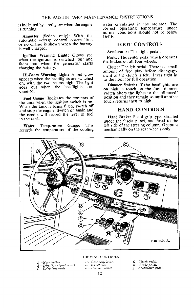
FOOT CONTROLS
Accelerator:
The right pedal.
Brake:
The center pedal which operates
the brakes on al1 four wheels.
Clutch:
The left pedal. There is a small
amount of free play before disengage-
ment of the clutch is felt. Press right in
to the floor for full operation.
Dimmer Switch:
If the headlights are
on high, a touch on the foot dimmer
switch alters the lights to the 'dimmed
position and they remain so until another
touch returns then to high.
HAND CONTROLS
Hand Brake:
Pisto1 grip type, situated
under the fascia panel, and fixed to the
left side of the steerinp column. Operates
mechanically on the rear wheels only.
DRIVING
CONTROLS
A--Horn
buflon. 1)-Gear shift
1et'e~.
G--Clufrh pedal.
B-I>irectzon sinal swilrh. E-Handbrake. H-Hrake Qerial.
C-Uefvosling ;'tnts.
F-Dimmrr
suitcli.
/-A
ccelerulor Qedal
THE AUSTIN
'A40'
MAINTENANCE INSTRUCTlONS
Cear Shift Lever: Should always be in
neutral when starting the engine. The
lever is mounted on the right side of the
steering column. To engage a gear,
,
depress the clutch and move the lever to
the required position as described on
page 15.
Choke Control: For use when starting
the engine from cold. Pull out to the
hituntil the engine fires, and return it
to the half-way position for rapid
warming up. The choke must be fully
released at the earliest posible moment.
lgnition Switch: Turn the key clockwise
to switch on. Do not leave the switch
'on' when the vehicle is stationary-the
red warning light is a reminder. The
ignition key rnay also be used for locking
the driver's door and the luggage or load
compartment.
Lighting Switch: This is the moulding
which surrounds the ignition switch.
Turn clockwise to the first notch to put
on the parking lights, and to the second
to put on the headlights. The headlights
are dimmed by foot operation.
Starter Switch Knob: Pull out the
control knob to start, and release as soon
as the engine fires. lf the engine fails to
start after a few revolutions, do not
operate the stiirter again until the engine
is stationary.
Direction Signals: The signals are con-
trolled from the center of the steering
wheel. Normally, after the vehicle has
turned a corner, they return automatic-
ally, but when only a slight turn has been
made it may be necessary to return thern
rnanually with the switch.
Heater and Defroster Controls (Sedan
only): These are situated centrally below
the instrument panel and provide the
means for regulating the heating and
demisting system. Full operating in-
structions are given on page
29.
Extra Air Control (Sedan only): A
supply of cold air,entirely independent of
the heating system,can be admitted to the
car interior for ventilation purposes, by
pulling out the control located on the
left-hand side of the heater and control
panel.
Heater Control Switch (Comrnercial
Vehicles): Turn to the right until a click
is heard. This starts the heater fan. The
further the control is turned the less will
be the speed of the fan, due to the fact
that a rheostat is incorporated.
Windshield Wipers: Tostart the electric
wipers pul1 out the wipers control. To
park, switch off by pressing the control
inwards when the arms are at the end
of the stroke. Do not try to push the
arms across the windshield by hand.
In the case of the Commercial Vehicles
the wipers are controlled by a rotary
switch situated at the top left-hand side
of the instrument panel.
Panel Light Switch: Pull out the switch
control knob to illuminate the instru-
ments. Only pperates when the parking
lights are 'on
.
In the case of the Comrnercial Vehicles
the panel lights are controlled by a
rotary switch situated at the top right
side of the instrurnent panel.
Horn Button: Mounted at the center of
the steering wheel, and can be operated
independently of the ignition switch.
Interior Light: Cornbined with a switch
in the roof.
SpareWheel: Secured at the rear of the
Sedan in the luggage cornpartment, and
under
the
load platform of the Com-
mercial Vehicles.
Seating: Adjustable front seats in
Sedan, single adjustable seat in Panel
Delivery and full width bench seat in
Pick-up. The Countryman driver's seat
rniiy be adjusted and the front passenger
seat hinges forward to give access to rear.
Doors: The right side front door, the
luggage compartment of the Sedan and
the rear doors of the Countryman and
Panel Delivery may be locked with the
igition key. The other doors may be
locked by lifting the incide door handle.
An additional safety lock is fitted tothe
rear door interior locking handles of the
Sedan. This device is intended to prevent
inadvertent opening of the doors, par-
ticularly by children, when the Sedan is
in motion.
Tolock the doors, turn the escutcheon
in a clockwise direction
on
the left door
handle and anticlockwise on the right
door handle This can only be effected,
however, when the handles are in the
unlocked position.

THE AUSTIN 'A40' MAINTENANCE INSTRUCTIONS
Engine Oil Filler:
Incorporated in
the valve rocker cover. Bayonet fitting
cap, with anchor cable to prevent loss.
Gasoline Filler:
On left rear side of
body; bayonet type cap, with anchor
cable to prevent loss.
Radiator Cap:
Screw type, incorporat-
ing water and steam trap.
THE SEDAN HOOD CATCH
Inxrlthefingers
tznd
push back lhe safely
cnlch.
Hood Catch
(Sedan onlv): To oDen
the hood pul1 upwards and forwardson
the handle formed by the 'Flying A'
Motif. This will have the effect of re-
leasing the locking catch and it will then
be possible to raise the hood an inch or
so until held by a spring-loaded safety
catch. lnsert the fingers and push back
this safety catch, when the hood may be
lifted right up. The hood is held open
by a stay clipped to its underside, and a
small locating cup is provided in the
radiator top tank to keep the stay secure
when in use.
The spring-loaded safety catch is
designed to hold down the hood while
driving in the event of the hood not
having been properly locked. When
closing the hood a slight pressure
exerted downwards on the hood top
will help the locking catch to engage
positively.
Hood Catch
(Commercial Vehicles):
To open the hood pull the control knob
situated below the fascia panel, on the
extreme right-hand side. The hood will
rise an inch or soand will then be held by
a spring-loaded safety catch, after which
the procedure is exactly the same as that
given for the Sedan.
In the case of the 'A40 Sports
Modrl
the hood is held open by a sliding stay
which is bolted from the underside of the
hood to the bulkhead.
STARTING
BEFORE starting the engine. See that the gear shift lever is in neutral and that the
handbrake is applied. If the engine is cold pull out the choke control. Do not pump
the accelerator.
Switch on the ignition and then pull
the starter control firmly. Release it if
the engine fails to start promptly. Allow
a short interval between each attempt to
start, and if the engine does not fire in a
reasonably short time look for the cause
of the trouble. Never pul1 the starter
control unless the engine is stationary.
As soon as the engine starts, release
the starter and push in the choke control
part way while the engine warms up.
Release the choke cornpletely as soon as
the engine will run without it.
When the vehicle has been out of use
for more than a month the gasoline in
the carburetor rnay have evaporated.
Before attempting to start the engine
refill the carburetor by operating the
priming lever on the fue1 pump, which is
located low down on the left side of the
engine.
The pumping action should be dis-
tinctly felt until the carburetor bowl is
full. íf this pumping action cannot be
felt, turn the engine with the starting
crank about one full turn, whereupon
the priming lever should be free to
PumP.
Do not allow the engine to race when
first starting up, as time must be allowed
for the oil to circulate properly. Let the

THE AUSTlN 'A40' MAlNTENANCE INSTRUCTIONS
engine idle fairly fast for a few minutes to warm up quickly, but always un-
before moving off, and engage high gear cover the radiator before driving off.
as soon as possible afterwards. Blanking There is a thermostat to assist in rapid
off the radiator will assist the engine warmingup.
BREAKING-IN THE NEW VEHlCLE
THEAustin 'A40' is designed and built with great care to high quality standards.
For that reason the owner will find that considerate treatment during the all-important
breaking-in period will be well repaid by trouble free running and the utmost in per-
formance throughout its life.
The following speeds should not be
ewceeded in the gears for the first 500
miles.
Low 2nd 3rd High
lt is most important to remember that
at no time during the breaking-in period
must the engine be over-loaded, as iri
attempting to ascend grades in high gear
at low vehicle speed. The load should be
eased by shifting down to a lower
gear.
Fierce acceleration must also be
avoided, and remember that the engine
should never be raced in neutral.
On completion of the first 500 miles
the breaking-in speed in each gear
may be progressively increased, but full
power should not be used until at least
1,500 miles have been covered, and even
then only for short periods at a time.
No engine or complete vehicle can be
considered fully broken-in until it
achieves 2-3,000 miles.
The use of upper cylinder lubricant is
recommended at al1 times, but most
particularly during the breaking-in
period. See centre pages for recom-
mended brands.

THE AUSTIN 'A40' MAINTENANCE lNSTRUCTIONS
THE
transmission has four forward speeds and a reverse. Start only in low gear, which
1s engaged by depressing the clutch pedal and moving the shift lever away from the
steering wheel and then upwards. Gradually release the clutch pedal, at the same time
gently depressing the accelerator and releasing the parking brake. The vehicle will move
forward, gathering speed in accordance with the amouct the accelerator is depressed.
Second gear is engaged by depressing
the clutch pedal, moving the shift lever
straight downwards and then releasing
the clutch pedal. Ease up on the accelera-
tor whilst shifting to a higher gear, and
gradually depress the accelerator when
the higher gear is engaged.
To engage third gear, move the shift
lever upwards into neutral, then towards
the sterring wheel, and finally upwards
again.
Engage high gear by moving the lever
straight downwards, parallel to the
steering wheel.
Down-shifting is an exact reversal of
the above procedure, except that the
accelerator must be kept depressed whilst
the gear is being shifted, in order to speed
up the engine in accordance with the
lower gear.
To engage reverse, which must only
be done when the vehicle is stationary,
move the shift lever towards the instru-
ment panel as far as it will go, at the same
time pulling outwards on the lever knob,
and then move the lever downwards.
Remember, however, that the gearing is
now lower than low gear. Consequently
release the clutch slowly until the vehicle
just begins to move, and then gently
depress the accelerator to give the speed
desired.
DO not 'ride the clutch' instead of
using the handbrake when temporarily
halted on an upgrade.
When descending a steep grade it is
advisable to engage an intermediate or
low gear. The engine will then provide
a useful braking action.
What Not to Do.
Do not
pul1 the starter control when a
gear is engaged.
Do not
forget to switch on the ignition
when starting the engine.
Do not
continue pulling the starter
control if the engine will not fire.
Do not
forget to release the choke
control as soon as possible after starting
the engine.
Do not
leave the ignition switched on
when the engine is stationary.
Do not
leave the vehicle in gear with
the handbrake off.
Do not
engage reverse gear when the
vehicle is moving forwards or fonvard
gear when the vehicle is moving back-
wards. Serious damage may result.
Do not
'ride the clutch' in traffic or on
an upgrade.
Do not
coast with a gear engaged and
the clutch pedal depressed.
Do not
run the engine at high speeds
for the first
500
miles.
Do not
race the engine in neutral at
any time.
Do not
run the vehicle with the radiator
completely blanked off.
Do not
fill the radiator with cold water
when the engine is hot.
Do not
under any circumstances run
the engine in a closed garage or similar
restricted atmosphere. The exhaust fumes
are highly poisonous and if inhaled will
quickly produce grave, if not fatal
results.
Skidding.
Skidding is usually due to the sudden
application of the brakes on an icy,
greasy or loose road surface, and may be
accentuated by unduly slack tyres. If the
rear wheels skid, release the brakes and
turn the steering wheel towards the
direction of the skid to regain wheel
grip on the road.
Wet Brakes
After the vehicle has been washed or
driven through water the brake linings
may be wet. Apply the brakes several
times in order to dry them. Wet brakes
are extremely dangerous.

THE AUSTIN 'A40' MAINTENANCE INSTRUCTIONS
REGULAR ATTENTIONS
THE
following is a convenient list of regular attentions which the vehicle should
receive to keep it in good mechanical condition. These instructions should be closely
followed whether the attentions are performed by the owner or the local garage.
The attentions under the Weekly headings are based on the asssumption that the
maximum mileage per week does not exceed 500.
Under more arduous conditions, such as very dusty or very muddy roads, long
distances at high speeds or with heavy loads, it will be advisable to attend to chassis
lubrication more frequently.
Every time gasoline is put into the tank, the engine oil level and the radiator water
level should both be checked. Top up if necessary.
EVERY 500 MILES OR
WEEKLY
Shackle Pins
:
These are on the rear
ends of the rear road springs and should
be given a charge of oil once a week.
There are two nipples, one on each top
shackle.
Front Suspension:
Apply the oil gun to
the lower arm joints where they meet the
knuckle pin housing
(C).
Knuckle Pins:
Apply the oil gun to the
two nipples on each knuckle pin. This
is best done when the vehicle is partly
jacked up, since the oil is then able to
penetrate to the thrust side of the
bushings
(G
and
D).
In the case of Commercial Vehicles,
which are supplied with a screw type
lifting jack, the load on the front suspen-
sion should be relieved by placing thejack
under the lowest point of the frame front
cross member, with the lipped end of the
liftingplatform firmly againstthe fonvard
side, and then partly raking the vehicle.
Steering Connections:
Apply the oil
gun to the steering center tie rod nipples
(2)
(A) and the steering side cross tube
nipples (4) (E and
F)
and top up the
steering idler
(B)
via the oil plug orifice.
N.B.-On no account should the
steering idler be overlooked, as lack of
lubricant in this component may cause a
serious breakdown due to the additional
load imposed on the steering box.
Brakes and Controls:
With the oil can,
oil al1 the handbrake linkage points,
brake and clutch pedal linkages and
carburetor control joints. Also oil al1
the gear shift control joints.
500 MILES
Engine:
On new and reconditioned
engines the pan should be drained and
refilled with new oil after the first 500
miles. At the same time as these changes
are made, the cylinder head nuts should
be tested and tightened if found necessary.
Transmission and Rear Axle:
After 500
miles on new vehicles, drain and refill
the transmission and rear axle.
Always drain the oil after a run, since
it will then flow more easily.

THE AUSTIN 'A40' MAIN
TENANCE INSTRUCTIONS
'I'HE
GEAR SHIIiT
.4-Clulch uperuli~rg shafl ntpple. B-Hand
bruke pivot nippb.
C,
U,E-Oiling pcinls.
EVERY 2,000 MILES OR
MONTHLY
Engine: Drain the pan and refill with
new oil. Capacity is 8.4 pints
(7
Imp.).
Transmission: Check the level and top
up if necessary. For access lift the floor
carpet and remove the rubber plug on
the right side of the transmission cover-
ing. The filler plug is then accessible.
Remove the plug and fill up to the
bottom of the threads. This gives the
correct level.
Clutch Pedal: With the oil gun, lubri-
cate the nipple at the base of the lever.
Brakes: Apply the oil gun to the
brake balance lever on the rear axle, the
handbrake pivot, and the brake pedal
pivot nipple.
Rear Axle
:
Check the level and re-
plenish if necessary. The correct oil
should br used and injected into,the axle
casing from underneath, using the
adapter on the oil gun.
First remove the plug, which is on the
right lower front side of the axle, then
place the end of the adapter into the oil
hole, and inject the oil.
The plug also serves as an oil level
indicator. Therefore, do not replace the
plug at once, but give time for the super-
fluous oil to run out if too much has
been injected. This is most important,
because, if the rear axle is overfilled the
lubricant may leak through to the brakes
and render them ineffective. Wipe away
the excessoil frorn the casing.
THE
PEDA1.S
A--0zling point. R-Clutch udiusttng rod.
C-
Oiling pcinf. TI-Uumbell i~nionnipple.
E-
Brake pedal nipple. F-Clutrh pedal nipple.
G-Dumbrll unrti~inipple.
Steering Column: Lubricate the felt
washer at the top of the steering colurnn
by adding a few drops of light machine
oil through the oil hole in the steering
wheel hub close to the steering column.
EVERY 3,000 MILES
Distributor Cam- and Drive-Shaft Bear-
ings: Lubricate the distributor cam-shaft
bearings by withdrawing the molded
rotating arm from the top of the dis-
tributor spindle and carefully adding a
few drops of oil round the screw exposed
to view. See page
25
for recommended
oils. Take care to refit the arm correctly
by pushing it on to the shaft and turning
until the key is properly located.
H40. 207.
A.
THE
I'ROPEL1.ER
SHAFT
.4
is
/he
cniwrsal joinl nipple.
18

Other manuals for A40 Somerset Sedan
1
This manual suits for next models
3
Other Austin Motor Company Automobile manuals

Austin Motor Company
Austin Motor Company FX4R User manual

Austin Motor Company
Austin Motor Company Austin Seven User manual

Austin Motor Company
Austin Motor Company Austin Seven User manual

Austin Motor Company
Austin Motor Company A40 Somerset Sedan Technical specifications

Austin Motor Company
Austin Motor Company LANDCRAB 1993 User manual


