Austin Motor Company Austin Seven User manual
l.
~
,
f
,~
I'
11
\;
1t
11
.
HANDBOOK
OF
PRICE 2/6
14th EDITION
THE
AUSTIN MOTOR CO. LTD.
LONGBRIDGE,Nr. BIRMINGHAM
"
T,I,g"ffi'
T']'phon" '
Cod,
, "SPEWILY, NORTHFIELD."
, CENTRAL 4140. KING'S NORTON 230.
, BENTLEY's.
LONDON SHOWROOMS, REPAIR DEPOT AND HIRE DEPT.:
479-483, Oxford Street, W.!.
(NEAR MARBLE ARCH)
T,I'g""" "AUSTINmE, LONDON:'
T.!,phon, " MAYFAIR6230
Also at 3, 5 and 7, RUE du' PARNASSE, BRUSSELS.
1
1. "fm~' " "" boo' 352 M
pi.", q.~' "', ..mb,',

The "AUSTIN
, ~II
j,
,
, i
.11
It 1
'1,1~1
r" ..1.
SEVEN" .
,
,
I I
\
~
I
".:
'.
it
,
2
iI.
...
CONTENTS
AMMETER READINGS
ATTENTIONS, D,ily
W"kly
Monthly
O""ion,I
BATTERY, The ...
BODYWORK, Care 01
BRAKES, Ad;",ting the,
BRAKE GEAR, Lnhri"tion of ...
BRAKES, R...lining ..,
CAR. Cont<ol of the ...
" Fe,tnre, 01 the ...
" The New
CARBURETTER, The
PAG'.
28
11
12
13
13
29
38
34
26
36
9-
5
7
14
15
15
15
25
33
20
28,
28
21
8
37
26
2!i
25
27
19
17
16
38
23
21
19
25
27
32
36
35
27
39
37
26
32
10
30
".
Adju,tment of
Slow Running 01
" Le,hge from
CLUTCH, Luhri"tioh of ...
COMBUSTION CHAMBER, CI..ning ...
COOLING SYSTEM
DYNAMO, The ...
ELECTRICAL EQUIPMENT. The
ENGINE,Luhri"tionof .
St"ting the
...
FAN
FRONT AXLE, Luhrication of ...
FUSE, Action of the ... '1:
GEARBOX, Luhri"tion of ..'
HUBS (Front ,nd Re,r), Luhri"tion 01
'IGNITION, F,ult, in
Re-timing
Sy,tem, The
LAMPS, Care of ,..
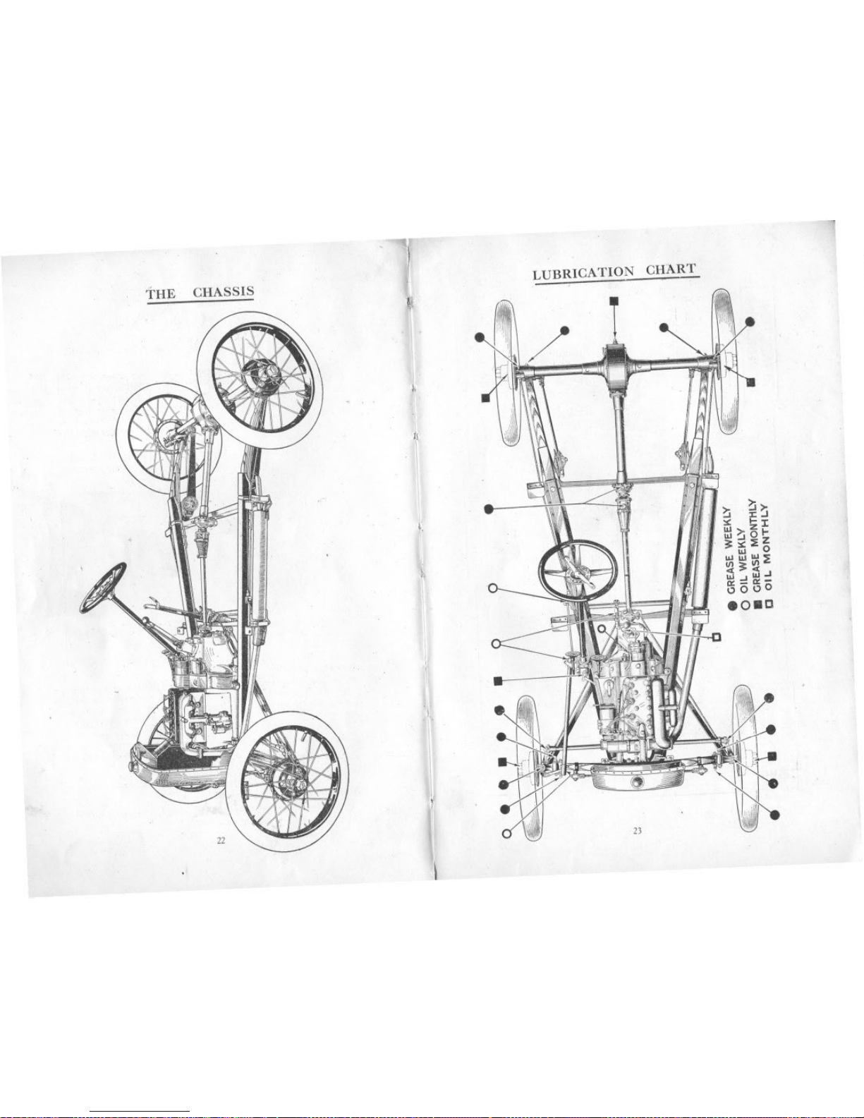
LUBRICATION CHART
LUBRICANTS ""'mmended
MAGNETO, Lubric,tion of
REAR AXLE, LubriCAtion01 ...
ROAD SPRINGS, Luh,ic"ion of
RUNNING ADJUSTMENTS .'..
SHOCK ABSORBERS, Adju,tment 01
STEERING. Adju,tmcnt 01 ...
STEERING GEAR. Luhri"tion 01
TOOLS, Supplied
TYRES ...
UNIVERSALJOINTS, Lubri"tion of
VALVE TAPPETS. Adju.tment 01
WHEEL, How to Ch,nge ,
WIRING, lItu,tr,tion of 3
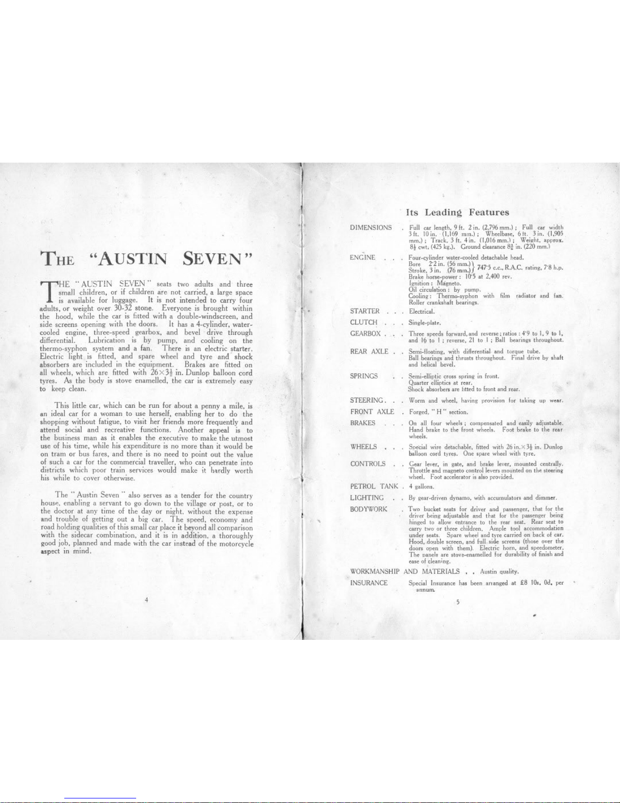
THE "AUSTIN SEVEN"
THE" AUSTIN SEVEN" seats two adults and three
smal! children, or if children are not carried, a large space
is availahle for luggage. It is not intended to carry four
adults, or weight over 30-32 stone. Everyone is brought within
the hood, while the car is fitted with a double-windscreen, and
side screens opening with the doors. It has a 4-cylinder, water-
cooled engine, three-speed gearhox, and hevel drive through
differential. Lubrication is by pump, and cooling on the
thermo-syphon system and a fan. There is an electric starter.
Electric light is fitted, and spare wheel and tyre and' shock
absorbers are included in the equipment. Brakes are fitted on
al! wheels, which are fitted with 26 X3t in. Dunlop bal!oon cord
tyres. As the body is stove enamel!ed, the car is extremely easy
to keep clean.
This little car, which can he run for about a penny a mile, is
an ideal car for a woman to use herself, enabling her to do the
shopping without fatigue, to visit her friends more frequently and
attend social and recreative functions. Another appeal is to
the business man as it enables the executive to make the utmost
use of his time, while his expenditure is no more than it would be
on tram or bus fares, and there is no need to point out the value
of such a car for the commercial travel!er, who can penetrate into
districts which poor train services would make it hardly worth
his while to cover otherwise.
The" Austin Seven" also serves as a tender for the country
house. enabling a servant to go down to the village or post, or to
the doctor at any time of the day or night. without the expense
and trouhle of getting out a hig car. The speed, economy and
road holding qualities of this small car place it beyond all comparison
with the sidecar combination, and it is in addition, a thoroughly
Koodjob, planned and made with the car instead of the motorcycle
aspect in mind.
4
,
,
..,.
r
11;
'0.'
';1
.
'
I
'
'I
11
'"
;I~
,
,
"';t,
DIMENSIONS
ENGINE
STARTER
CLUTCH
GEARBOX.
REAR AXLE.
SPRINGS
STEERING.
FRONT AXLE
BRAKES
WHEELS
CONTROLS
PETROL TANK
LIGHTING
BODYWORK
,
Its Leading Features
. Full m leng,h, 9 It. 2 in. (2,796mm.); Full m width
3 It. 10in. (1.169 mm.); Wheelb"e, 6 tt. 3 in. (1,905
mm.); T"ck. 3 ft. 4 in. (1,016mm.); We;.ht. appcoX.
8! cwt. (425kg.). Ground clmance 8i in. (220 mm.!
. Four-cyl;nder water-cooled detachable head.
Bore 2'2 in. (56 mm.)}. '.
Stcoke. 3in. (76 mm,) 7475 C.c"RAC. "tmg, 7 8 h.p.
B"ke hom-power; 10'5 at 2,400 rev.
Ign;tion: Magneto.
Oil cireulation: by pump.
Cooling: Thermo-,yphon with film "diator and fan.
Roller ",nbhalt bming,.
. Eledrical.
. S;ngIe-plate.
. Three ,peed, forward,and mer,,; "t;ca :4'9 '0 I, 9 to I,
and 16 to I; rovem, 21 to.f ; Ball b",;ng, throughout.
. Semi-IIeating. with diflerentiaI and torque tube.
Ball.bearing' and thm,t, thcoughout. F;nal drive by ,halt
and helical bevel.
Semi-elliptic crca, ,pr;ng m hont.
Quarter ellipt;" at rear.
Shock ab,orben; are httd 10 front and r"'.
Worm and wheel, having pcovi,;on for taking up wm,
Forgd. .. H" "dion.
On all four wheel,; compemated and ea,ily adiu,tabIe.
Hand brake to the fcont wheela. Foot b"k, to the re"
wheel,.
Spe,;al wire detachable. fitted with 26 ;n.X 3t in. Dunlop
balloon cord tyre,. One 'pare wheel with tyre.
G", lever, ;n gate, and b"ke lever. mounted eentcally.
Throttle and magnetocon'colleve" mounted on th, 'teer;ng
wheel. Foot accelerator ;, a"o provided.
4 gallon"
By ",,-dr;ven dynamo, with accumulato" and dimmer.
. Two bucket "at, for driver aod pa..enger, that for ,he
driver being adiu,'able and that for the p""o,er being
h;o,ed to allow entranee to the rear ,eat. Rear "at to
carry two or three children. Ample '001 accommoda,ion
under "at" Spare wheel and tyre c",ied on back of car.
Hood, double "'eeo, aod full,ide "reem (thoa< over ,he
doo" open with them), Electr;c horn. and ,peedometer.
The Daoeb are ,'ove-enamelld for durability of fini,h and
ea" ofcI"ning.
WORKMANSHIPAND MATERIALS, , Au,tin qu,Iity.
INSURANCE Special In,mance h" beeo anaoged at £8 IQ,. Od. per
,noum.
5.
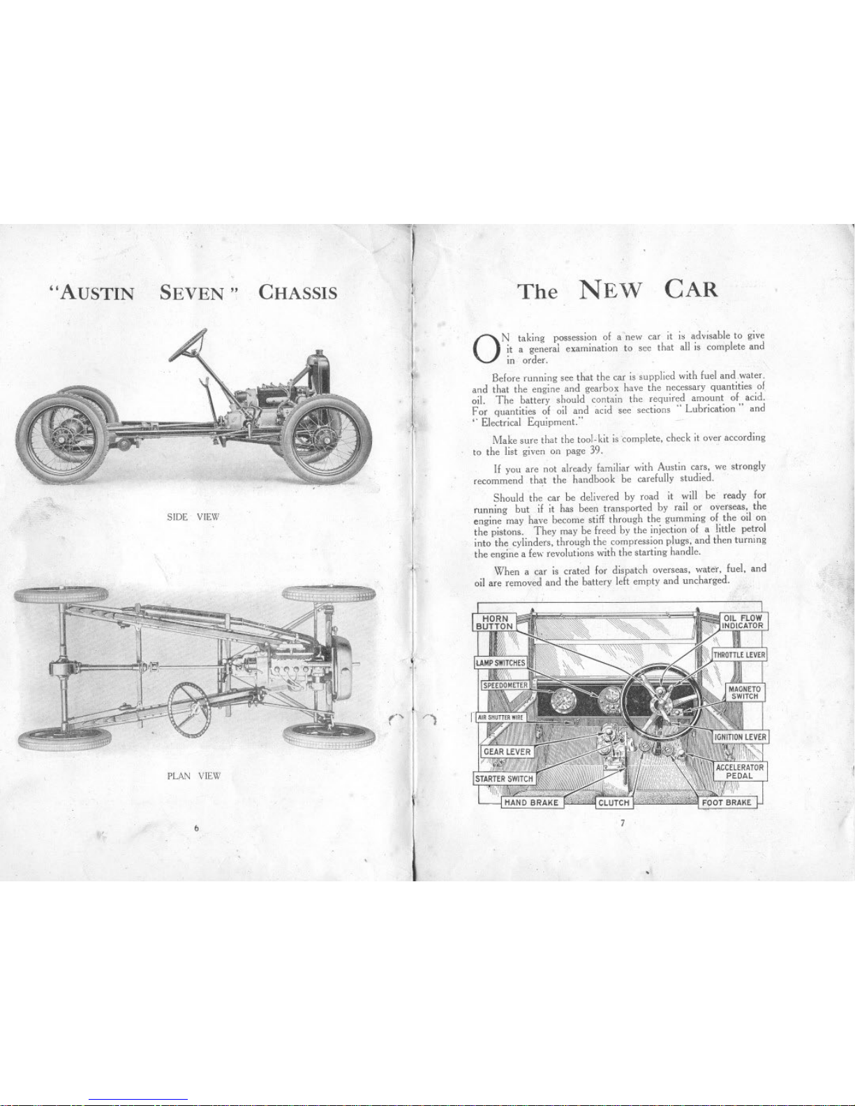
"AUSTIN SEVEN" CHASSIS
SIDE VIEW
PLAN VIEW
"b
("
;1
,It
i
'I
f
J,
~
if!
'1
The NEW CAR
ON taking possession of a new car it i, advisable to give
it a general examination to see that all is complete and
in order. .
Before running see that the car is supplied with fuel and water,
and that the engine and gearbox have the necessary quantities 01
oil. The battery should contain the required amount of acid.
For quantities of oil and acid see sections" Lubrication" and
,. Electrical Equipment."
Make sure that the tool. kit is complete, check it over according
to the list given on page 39.
If you are not already familiar with Austin cars, we strongly
recommend th~t the handbook be carefully studied.
Should the car be delivered by road it will be ready for
running but if it has been transported by rail or overseas, the
engine may have become stiff through the gumming of the oil on
the pistons. They may be freed by the injection of a little petrol
into the cylinders, through the compression plugs, and then turning
the engine a few revolutions with the starting handle.
When a car is crated for dispatch overseas, water, fuel, and
oil are removed and the battery left empty and uncharged. '"
7
.
,!
*
'~
Starting the Engine
Make'sure that the change speed lever is in neutral position.
and the hand brake on.
Turn on petrol tap at the bottom of the petrol tank (this will
be found under the bonnet).
Set the engine controJlevers at the top of the steering wheel
as follows: Throttle-open about iin. Ignition-almost fully'
advanced.
Give the engine a few turns with the starting handle to make
sure that the crankshaft is free, then switch on. Pull out the wire
on the instrument board to close the carburetter air inlet, ahd again
give the crankshaft a few sharp turns by means of the starting
handle, making sure to pull the handle upwards to commence with.
Be sure to release the air shutter wire after the engine has started.
Do not try to start the engine when cold by the electric starter,
It is most important that the engine be not allowed to race
when first starting liP, as time must be allowed for the oil to circulate
and lubricaie various bearings.
Difficulty in starting may be caused either through suc'king too
much petrol into the cylinder, or too little. ,I! one starts with the
throttle all but closed, a strong suction takes effect on the pilot jet,
and it is seldom necessary to flood the carburetter, and in any case
it should only be flooded slightly. I! petrol is passing through the
carburetter the suction can generally be heard. ' I! the engine fail.
to start and there is a good deal ofp'etrol overflowing from the
carburetter it is almost certain that the mixture getting into the
cylinder is too rich. In this' case open throttle about half way.
This reduces the suction effect by allowing a greater. proportion of
air to enter the engine. On firing, the engine may race away, but
will soon settle down to steady running. I! the engine does not
fire, close the thiottle entirely and try again. After a stop in hot
weather, failure of the engine to start is more likely to be due to
too rich a mixture than one too lean, and one should stop the
engine by the switch only after quite closing the throttle. Re.start
the enginewith the throttle closed. '
The car itself should never be allowed to run at
high speeds for the first 300 miles.
I! after the foregoing instructions have been carried out under
the heading of .. Starting the Engine," but the engine fails to start
the reason will probably be due to faulty ignition or carburation
Ignition: First examine the wires and see that the sparking
plugs are connected. Then test the gap of the plug points by means
of the thick end of the gauge provided in the tool kit. I! the points
are dirty, clean them before replacing the plug. For fuller details
on the ignition system see page 16.
Carburation: The slow running jet may be stopped up
or a main jet choked. Blow them out with a tyre pump. For
fuller details ahout the carburetter see page 14.
8
J
CONTROL OF THE' CAR
Setting of Control Levers
.. ~FTER having started th'e engine, keep the ignition lever in
the advanced positiori; should the engine commence to
.. rumhle " or run roughly, retard the lever, hut advance it
again as soon as the load on the engine is lessened. The" gas ..
lever should he set generally for slow running and the. speed of
the car controlled by the accelerator pedal.
'.1',
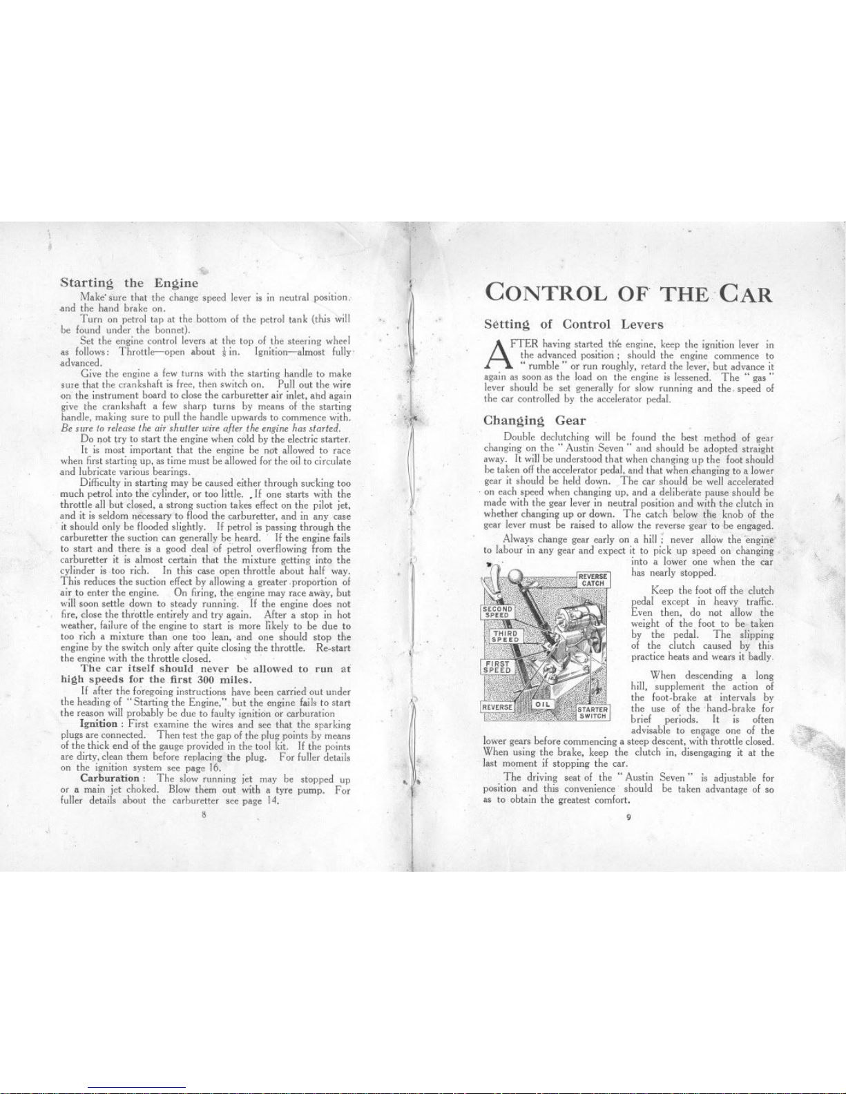
>Changing Gear
Double declutching will be found the best method of gear
changing on the" Austin Seven" and shonld be adopted straight
away. It will be understood that when changing np the foot should
be taken off the accelerator pedal, and that when changing to a lower
gear it should be held down. The car should be well accelerated
,on each speed when changing up, and a deliberate pause should be
made with the gear lever in neutral position and with the clutch in
whether changing up or down. The catch below the knob of the
gear lever must be raised to allow the reverse gear to be engaged.
Always change gear early on a hill: never allow the 'engirie" ,
to labour in any gear and expect it to pick up speed on changing,
.~' into a lower one when the car
has nearly stopped.
Keep the foot off the clutch
pedal except in heavy traffic.,
Even then, do not allow the
weight of the. foot to be taken
by the pedal. The slipping
of the clutch caused by this
practice heats and wears it badly
When descending a long
hill, 'supplement the action of
the foot.brake at intervals by
the use of thehand.brake for
brief periods. It is often
advisable to engage one of the
lower gears before commencing a steep descent, with throttle closed.
When using the brake, keep the clutch in, disengaging it at the
last moment if stopping the car.
The driving seat of the" Austin
position and this convenience should
as to obtain the greatest comfort. >
/
4,
f.'
11
. ,D '.
(I
.
"$
",,'~'
.' ."'.
. ~F'
*
,I~). Seven" is adjustable for
be taken advantage of so
'"
.~
"
,
9

.How TO
CHANGE A WHEEL
WHEN it becomes necessary to change a wheel because
of a puncture or for any other cause. it will be necessary
first to remove the number plate. The spare wheel is
fastened on a bracket with three screws. in a sim;lar manner to
its fixing on the hub.
To detach a road wheel from the hub loosen the three right-hand
threaded nuts A which are in the hub of the wheel. by means of
the brace; it is not. necessary to remove them entirely. Now pull
the wheel outwards about Jrin. .and turn it so that the large hole
will pass over the nut. THe wheel can now he pulled 011the .bub.
When replacing make sure that the large pole in tbe hub is properly
fitted over its peg. <'.'
Should difficulty be experienced upon the first occasion of
removing the wheel from the hub, the wheel nuts may be screwed
right of!, The brake drum will then come away with the wheel.
To free this from the wheel. insert a screwdriver between the two
flanges, Before replacing, wipe the outside of the brake drum
and the inside of the hub with an oily rag. Great care is
necessary in order that no damage is done to the flanges. .
IQ
>PERIODICAL
ATTENTIONS
THE importance of giving careful attention
and regular inspection to the modern auto-
mobile cannot be over-estimated. If this is
done systematically considerably greater pleasure
will be derived from motoring as the car will always
be kept in tune and will not require adjusting at
inopportune moments.
Further, by following out the instructions given
in this book, expensive repairs may even be avoided,
as much of the trouble experienced by motorists
could have been avoided if attention had been given
.to details at the proper time.
The fol1owing instructions are arranged on a daily.
weekly, or monthly basis. The estimated needs
of the car for such periodical attention is based. on
the assumption that the maximum mileage for a
week wi1l not exceed 300 miles.
,
Daily Attentions-See also Lubrication
Chart, page 23.
1. Examine water level in radiator and
fill np to within 2 in. of the top. Always
use the strainer when re-filling as
dirty water will cause the radiator
film to become choked.
2. Examine oil level in the crankcase
and add more oil if necessary. The
teJJ-tale dipper rod indicates the level
of the oH (see illustration, page 21).
Fill up the petrol tank if necessary.
Care should be exercised when filling
the tank not to spill the petrol over
the engine.
3.
11
';
Monthly Attentions
Weekly 1. Examine the oil level in the gearbox
which should contain two-thirds of
a pint, or measure 2-2! in. deep.
Attentions
1. With the grease gun charge-,
Front spring shackle pins (4).
Rear spring pins (2).
Front wheel swivel pins (2).
Steering cross tube (2).
Fan bearing.
as'
2. Charge the back axle case with a gunfull
of grease and oil mixed half and half.
/. 3.
2. Oil the following-
Handbrake gear.
Pedal gear and jaw joints.
Engine control. and ball joints.
Clutch release ring.
Rear Brake cam spindles (2).
-" 4.
Fill all the hubs with
instru'cted on page 27.
Charge with grease the steering worm
case through the connection.
grease,
Examine the battery and see that the
connections are tigh~.
6. Give a cbarge of grease to the nipple
.on the fan spindle.
5.
3. Examine both sets of brakes, and adjust
if necessary. For method of doing this
see page 34. Occasionally
4. Examine all bolts and nuts, and any other parts such as
steering connections, neglect of which might lead to failure and
breakdown which would be followed by an expensive repair and
the inability to use the car for a lengthy period.
Inject high speed grease such as
Messrs. Stern's" Diathol" into the
universal joint at the rear end of the
propeller shaft, !md yellow grease into
the front end of the torque tube.
Oil the joints of the steering side tube. Spring clips and cylinder head nuts should be tightened
up occasionally when the car is new. and the nuts whenever the
cylinder head has been recently replaced.
It is advisable occasionally to remove all the road wheels and
clean inside the hub and wipe with an oily rag.
This emures the rapid removal of a wheel in case of a
puncture when on the road.
5.
"Utile, but often" should be the motto in lubrication.
12 13
.

}
I
The
CARBURETTER
,Method of Adjustment
Before altering the carburetter setting, turn off the petrol
bY'means of the tap underneath the tank. A jet key is sent out
with each car for the purpose of taking out the main and com-
pensating jets. The caps below the jets must be removed by
means of the adjustable spanner, when the 'jets can be unscrewed
with the special key. When replacing either, make sure that they
have washers on them, and are well down on the shoulder.
THE. following instructions have reference to the Zenith
c",buretter, adjusted by determining ihe correct sizes of
the choke tube, main jet and compensator, The purpose
of the choke tube is to obtain the correct velocity of air around the
jet in order to get the best mixture at all speeds. The main jet
I
\I
ij
jl
Slow Running
Too much petrol for slow running causes cho king and hesita-
tion in the pick-up. Although the engine may start easily and keep
running, it commences to run jerkily. A want of petrol, on the
other hand, causes a loss of power and misfiring at the same time.
It is, therefore, necessary to regulate the slow. running as carefully
as possible. First release the small locking screw A and then with-
draw the tube B, as illustrated. To reduce the quantity of petrol
unscrew the lower part C of the tube B, one notch at a time.
Reverse the operation to increase the flow of petrol. The jet
can be unscrewed from the lower part of the tube. There are
other factors quite apart from the carburetter which have a great
influence on slow running (slow running when the engine is oul
of gear and the car is stationary). These factors are:-
Cylinder head ,and induction pipe joints not air-tight.
Valve guides worn. Valves not gas tight.
Ignition too much advanced.
These points must always be taken into consideration, and
one should not blame the carburetter only if slow running is not
satisfactory,
i
.
has most influence at high speeds, The compensator, which
corrects the irregularities of the ,main jet flow due to differences
in engine speed, has Ihe greatest influence at slow speeds. Besides
these three parts there is a special device to provide for slow
running. The carburetter is tuned and set at the works to give
the best results under ordinary conditions; should the car be taken
to districts where the atmospheric conditions vary considerably, or
a different fuel be used, it may be advisable to adjust the
carburetter accordingly. Before making alterations to the carburetter,
make qtlite sure that the engine is in good running order.
particularly the ignition. The standard carburetter setting is:-
Choke ... .., 15mm,
MainJet ... ,.. '70mm,
CompensatingJet ..' '75mm.
14
. Leakage from the Carburetter
The cause is that the flo~t control is out of adjustment-the
floatperforated-or there isdirt on the needleseating,wh,ichshoul~
be cleaned. The two defects first mentioned should be remedien
by an expert:
1
--.-
t;
"'/
The B.L.I..G. Magneto
INthe B.L.LC. magneto the magnet rotates while the armatnre;
with its Iow and high tension windings, remains stationary.
. Slip rings, long rotating brush holders, collector brush holders
and so on, have been replaced by a short stationary connector
piece leading the high tension current from the stationary armature
to the stationary distributor terminal. The contact.breaker is
also stationary, the cam being revolved instead.
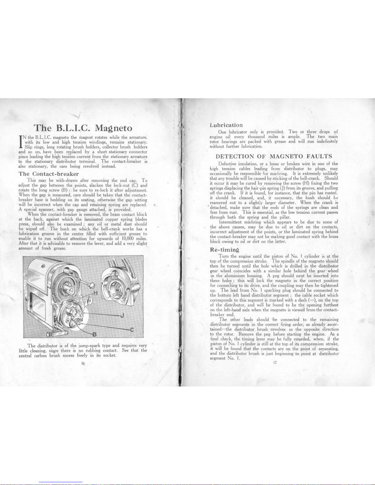
The Contact-breaker
This may be with.drawn after removing the end cap. To
adjust the gap between the points, slacken the lock.nut (C) and
rotate the long screw (B): be sure to re.lock it after adjustment.
When the gap is measured, care should be taken that the contact-
breaker base is bedding on its seating, otherwise the gap setting
will be incorrect when the cap and retaining spring are replaced.
A special spanner, with gap gauge attached, is provided.
When the contact-breaker is removed, the brass contact block
at the hack, against which the laminated copper spring blades
press, should also be examined; any oil or metal dust should
be wiped off. The bush on which the bell.crank works has a
lubrication groove in the centre filled with sufficient grease to
enable it to run without attention for upwards of 10,000 miles.
After that it is advisable to remove the lever, and add a very slight
amount of fresh grease.
...
The distributor is of the jump.spark type and reqUIres very
little cleaning, si'1ce there is no rubbing contact. See that the
central carbon brush moves ifeely in its socket.
16
/
J
.II~j
t
~
"1
It
~i
k i
Ii
'.
11~ ~
.,
1:."
I
!
"ti'J
I
I
(I:
.
,
/
/
Lubrication
One lubricator only is provided. Two or three drops of
engine oil every thousand miles is ample. The two main
rotor bearings are packed with grease and will run indefinitely
without further lubrication.
DETECTION OF MAGNETO FAVLTS
Defective insulation, or a loose or broken wire in one of the
high tension cables leading from distributor to plugs, may
occasionally be responsible for mis hring. [t is extremely unlikely
thai any trouble will be caused by sticking of the bell.crank. Should
it occur it may be cured by removing the screw (H) fixing the two
springs displacing the hair.pin spring (]) from its groove, and pulling
off the crank. If it is found, for instance, that the pin has rusted,
it should be cleaned, and, it necessary, the bush should be
reamered out to a slightly larger diameter. When the crank is
. detached, make sure that the ends of the springs are clean and
free from rust. This is essential, as the Iow tension current passes
through both the spring and the pillar.
Intermittent misfiring which appears to be due to none of
the above causes, mav be due to oil or dirt on the contacts,
incorrect adjustment 01 the points, or the laminated spring behind
the contact.breaker may not be making good contact with the brass
block owing to oil or dirt on the latter.
Re-timing
Turn the engine until the piston of No. 1 cylinder is at the
top of the compression stroke. The spindle of the magneto should
then be turned until the hole whicb is drilled in the distributor
gear wheel coincides with a similar hole behind the gear wheel
in the aluminium housing. A peg should next be inserted into
these holes: this will lock the magneto in the correct position
for conne~ting to its drive, and the coupling may then be tightened
up. The lead from N~. 1 sparking plug should be connected to
the bottom left hand distributor segment; the cable socket which
corresponds to this segment is marked with a dash (-), on the top
of the distributor, and will be found to be the opening furthest
on the left. hand side when the magneto is viewed from the contact-
breaker end.
The other leads should 'be connected to the re';'aining
distributor segments in the correct firing orde" as already ascer.
tained-the distributor brush revolves In the opposite direction
to the rotor. Remove the peg before starting the engine. As a
final check, the timing lever may be fully retarded, when, if the
piston of No. I cylinder is still at the top of its compression stroke,
it will be found that the contacts are on the point of separating,
and the distributor brush is just beginning to point at distributor
segment No. I.
#.
17
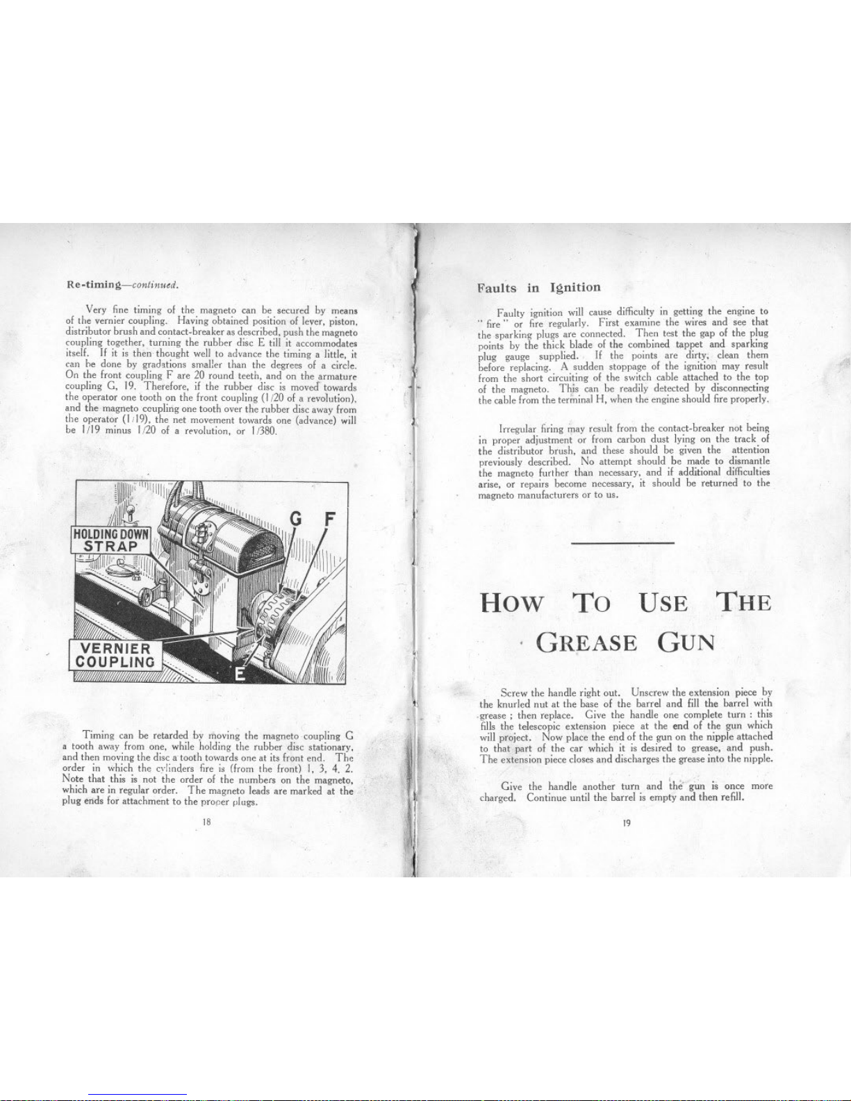
Re-timing-continued.
Very fine timing 01 the magneto can be secured by means
01 the vernier coupling. Having obtained position 01 lever, piston,
distributor brush and contact-breaker as described, push the magneto
coupling together, turning the rubber disc E till it accommodate,
itsell. If it is then thought well to advance the timing a little, it
can he done by grad,tions smaller than the degrees 01 a circle.
On the Iront coupling Fare 20 round teeth, and on the armature
coupling G, 19. Therelore, il the rubber disc is moved towards
the operator one tooth on the Iront coupling (1/20 01 a revolution),
and the magneto coupling one tooth over the rubber disc away Irom
the operator (I ;19), the net movement towards one (advance) will
be 1/19 minus 1/20 01 a revolution, or 1/380.
Timing can be retarded by moving the magneto .coupling G
a tooth away Irom one, while holding the rubber disc stationary,
and then moving the disc a tooth towards one at its Iront end. Thc
order in which the cylinders fire is (from the Iront) I, 3, 4. 2.
Note that this is not 'the order 01 the numbers on the magneto,
which are in regular order. The magneto leads are marked at the
plug ends lor attachment to the proper plugs.
18
, .ij
'f
.,,:1.
t
.
or,
(
~
Faults in Ignition
Faulty ignition will cause difficulty in getting the engine to
..fire" or fire regularly. First examine the wires and see that
the sparking plugs are connected. Then test the gap 01 the plug
points by the thick blade 01the combined t;lppet and sparking
plug gauge supplied. If the points are dirty; clean them
belore replacing. A sudden stoppage 01 the ignition' may result
Irom the short circuiting 01 the switch cable attached to the top
01 the magneto. Thjs can be readily detected by disconnecting
the cable Irom the terminal H, when the engine should fire properly.
Irregular firing <ray result Irom the contact-breaker not being
in proper adjustment or Irom carbon dust lying on the track 01
the distributor brush, and these should be given the attention
previously described. No attempt should be made to dismantle
the magneto lurther than necessary, and il additional difficulties
arise, or repairs become necessary, it should be returned to the
magneto manulacturers or to us.
How To THE
USE
GREASE
.GUN
,
Screw the handle right out. Unscrew the extension piece by
the knurled nut at the base 01 the barrel and lill the barrel with
.grease ; then replace. Give the handle one complete turn: this
fills the telescopic extension piece at the end 01 the gun which
will project. Now place the end 01 the gun on the nipple attached
to that part 01 the car which it is desired to grease, and push.
The extension piece closes and discharges the grease into the nipple.
Give the handle another turn and the- g~ is once more
charged. Continue until the barrel is empty and then refill.
19
The
COOLING SYSTEM LUBRICATION
ONE of the following oils is recommended: Stern's Sterna I
WW.. Price's Motorine C. If the oil' is too thick it
will tend to clog and carbonise, and if too thin it might
lead to scoring of the pistons and bearings. Assurance that oil
is continuously circulating is given to the driver by means of the
tell-tale button on the instrument board which protrudes when the
oil is circulating.
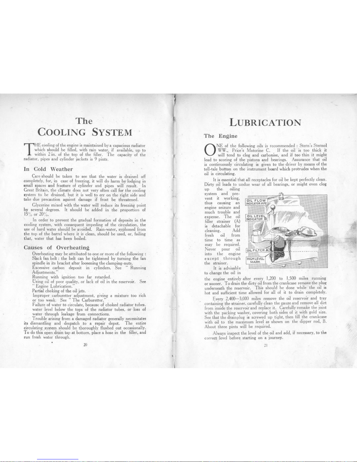
ltis essential that all receptacles for oil be kept perfectly clean.
Dirty pil leads to undue wear of all bearings, or might even clog
up the. oiling
system and pre-
vent it war king,
thus causing an
engine seizure and
much trouble and
expense. The oil
filler strainer (A)
is detachable for
cleaning. Add
fresh oil from
time to time as
may be required.
Never pour oil
into the engi ne
except through
the strainer.
It is advisable
to change the oil in
the engine entirely after every 1,200 to 1,500 miles running
or sooner .To drain the dirty oil from the crankcase remove the plug
underneath the reservoir. This should be done while the oil is
hot and sufficient time allowed for all of it to drain completely.
Every 2,400-3,000 miles remove the oil reservoir and tray
containing the strainer, carefully clean the gauze and remove all dirt
from inside the reservoir and replace it. Carefully remake the joint
with the packing washer, covering both sides of it with gold size.
See that the drain plug is screwed up tight, then fill the crankcase
with oil to the maximum level as shown on the dipper rod, B.
About three pints will be required.
Always inspect the level of the oil and add, if necessary, to the
correct level before starting on a journey. .
The Engine
THE cooling of the engine is maintained by a capacious radiator
which should be filled, with rain water, if available, up to
within 2 in. of the top of the filler. The capacity of the
radiator, pipes and cylinder jackets is 9 pints.
In Cold Weather
Care should be taken to see that the water is drained of!
completely, for, in case of freezing, it will do harm by lodging in
small spaces and fracture of cylinder and pipes will result. In
Great Britain, the climate does not very often call for the cooling
system to be drained. bnt it is well to err on the right side and
take due precaution against damage if frost be threatened.
Glycerine mixed with the water will reduce its freezing point
by several degrees. It should be' added in the proportion of
15% or 20%. .
In order to prevent the gradual formation of deposits in the
cooling system, with consequerit impeding of the circulation, the
use of hard water should be avoided. Rain-water, syphoned from
the top of the barrel where it is clean, should be used, or, failing
that, water that has been boiled.
Causes of Overheating
Overheating may be attributed to one or more of the following:
Slack fan belt: the belt can be tightened by turning the fan
spindle in its bracket after loosening the clamping-nuts.
Excessive carbon deposit in cylinders. See" Running
Adjustments."
Running with ignition too far retarded.
Using oil of poor quality, or lack of oil in the reservoir. See
.. Engine Lubrication."
Partial choking of the oil jets.
Improper.. carburetter' adjustment, pvmg a mixture too rich
or too weab See" The Carburetter."
Failure of water to circulate, because of choked radiator tubes,
water level below the tops of the radiator tubes,. or loss of
water through leakage from connettions.
Trouble arising from a damaged radiator generally necessitates
its dismantling and despatch to a repair depot. The entire
circulating system should be tllOroughly flushed out occasionally.
To do thisJopen drain tap at bottom, place a hose in the filler, and
run fresh;';ater through.
1
,l
f
I
"
,
I
-11
It~
III
20
ill
,~
,',
~~
-.
2t
--
-
Eo<
~
.(
:I:
0
Z
0
.....
Eo<
<
0
.....
~.
~
::>
~
A'H.1.NOW 110 Cl
A1W.LNOW3S'9'3!1~ .
A1)t33M 110 0
A1)t33M 3S'9'3!1~ .
~
N
r
"- :: =-~-=~ c- ~,""---=---. ~. :;. :=.0- .--'.-- -- CO"= ..
=.. ---=~
~.
:I:
'Eo<
N
N
<fJ
.....
<fJ
<fJ
<
:I:
0

zO:
00
-I-
I-<t
(.)U
I.IJ-
ZC
Z~
00
(.)1-
01-
I-~
L&JXC)
C1(1) Z
<t:E
V)«-
V)UQ::
if~«
-,oLIJ
-a::fXI
0....
... a.
~'
::J
Q.
>
.'«
24
.
.,
~Tbe main bearings 01 tbe engine are 01 tbe roller type, and
tbe oily vapour in tbe crankcase is quite sufficient to lubricate tbese,
Tbe pistons are also. lubricated by tbe oily vapour.
Lubrication 01tbe big-ends is ellected by catcbing oillrom tbe
pump-led jets in pockets on tbe cranksbalt webs.
It is advisable to make sure tbese jets are always clear a"d' to
do so tbe plugs over tbe jets (see illustration 0" page 24) sbould
be occasionally removed and. a piece 01 stiff wire i"serted tbrougb
tbe jets, Tbis prevents loreign matter accumulati"g in tbe
jets a"d cboki"g tbem.
Gearbox
A suitable oil for tbe gearbox is tbe same as that used in tbe
engine; but illor a"y reason a"otber brand 01oil is used it sbould
be 01 about tbe same consistency and no tbicker, otberwise it will
not reacb all tbe bearings. Tbe deptb 01 tbe oil should "ever
be less tha" I i", or. more tban 2,\ in. It can be measured by a
rod i"serted through the filler plug hole. The maximum qua"tity
is approximately ""'".pi"t. Tbe correct oil level should be
maintained; excess of oil will leak Irom tbe bearings and seriously
.ffect the clutch. causing it to slip; on tbe otber band there must
be sufficient oil to prevent wear,
The gearbox sbould be drai"ed entirely alter the /irst 500.800
miles, and then alter every 4,000 or 5,000 miles, when any grit,
etc., which may bave collected will drain away through tbe plug
hole in the sump.
Clutch
The clutch
surlaces being
01 a labric ma-
terial must be
kept Iree from
oil and grease,
or the clutch
willlail to grip.
It is necessary
to lubricate the
operating ring
at point A, as
show" on tbe
sketch, o"ce a
week.
Rear Axle
For tbe rear axle attention: every 1,200 to 1,500miles sbould be
sufficient. A mixture 01 yellow grease a"d engine oil 01 equal parts
sbould be used and injected witb tbe grease gun supplied witb tbe car.
Do not inject too mucb grease at anyone time as tbe Ielt rings will
lail to bold tbis grease in tbe axle case, and it will tben leak through
0" to tbe brake drums and preve"t tbem I.rom being effective.
25
i
,I.
"
.,.
'I
I;<-
"
i)
,.
\

The makers recommend that a good quality" high-speed"
grease be used. This is of a dark brown colour. and will remain in
the joint longer than the ordinary yellow grease.
The. rear universal joint being ot mctal, must be kept well
lubricated at A on account of the movement of the rear axle.
It should be one of the points to have strict attention. Access for
greasing this, together with the grease connection B on the end
of the torque tube,
is obtained through
a cover C in the floor
of the body, asshown
on the illustration
adjoining.
Rear Universal Joint Hubs (front)-continued.
Fill the hub with grease
until it is seen to exude from
the flutes, or slots, at the
base of the adaptor. It is
important that the hubs are
not given too much grease,
otherwise the brakes will
not be effective.
Hubs (rear)
,
Remove the road
wheel. Turn the wheel
until the nipple" A" is at
the top. Inject grease into
the hub; one push down of-
the telescopic extension
piece is sufficient for or-
dinary maintenance pur-
poses, but when it is desired to give extra attention to the lubrication
of the rear hubs the nipple can be extracted and the adaptor already
referred to, inserted in its stead, the same procedure being adopted
as that described for the front.
Brake Gear
On each of the
rear brakes there is a
.Iubricator for oiling
the cam spindle
bearing. These and
all other joints, etc., should be oiled once a week.
,The front brake cam spindle is lubricated from the swivel
pin as shown at E, on illustration.
Front Axle
The swivel pins are lubricated with the grease gun.
Hubs (front)
Remove the road wheel. Turn the hub until the plug HA"
is at the top. Screw out the plug and screw in the adaptor illustrated
which is provided in the kit.
Steering Gear
To obtain easy steering it is important to give it regular
attention as regards lubrication. The grease gun connection is
on the top of the worm case, and if a charge is given once a month
it is sufficient to lubricate the bearings of the worm and worm wheel.
and also lubricate the worm itself. The bearing at the top of the
column, just under the steering wheel. can be given a little oil from
the oil-can. The steering connections on the side rod and the
nipples at the end of the cross rod given a charge of gr~ase once
a week.
Road Springs
The ends of the road springs where they are attached to the
axles are provided with grease gun connections, and should be
given a charge once a week if the car is continually used. After
a long period of use it is advisable to lubricate the leaves of the
spring with a warm mixture of white lead and tallow in equal parts.
This can best be applied with a stiff br~sh, the leaves being eased
apart by a screwdriver; first jack up the car (not under the axles)
to take the weight off the springs.
27
26

ELECTRICAL EQUIPMENT
THE lighting equipment is a CAV. 6-volt system. Very
little attention is required to keep this in satisfactory working
order. .
Should difficulties arise that cannot be understood or remedied
from the information given below, the difficulty should at once
be referred to the Austin Service Department or the nearest depot.
Dynamo
The dynamo should be kept" on " as a rule. It is designed
to be self-regulating, and the only parts which call for any
attention are the commutator and brushes. To examine the
commutator and brushes all that is necessary is to remove the
cover. The commutator should be kept dean using a piece of
ordinary soft rag. To dean a dirtv or neglected commutator, use
very hne glass paper, but this should only be done in extreme cases.
Blow away any
carbon dust, see
that the carbon
brushes are wear-
ing evenly, and that
they run freely in
their slots. also that
the flexible leads
to the brushes
are not .caught
in any part of
the brush gear.
There is a
lubricator at each
end of the machine. A drop or two of engine oil in each, every
thousand miles or so, is sufficient. The best oil to use is ordinary
engine oil. When the machines are hrst assembled the bearings
are packed with grease which lasts for a long time.
Ammeter Readings
When the engine is running fairly fast and no lamps are in use,
the ammeter pointer should give a "charge" reading of 7 or
8 amp., or with the lamps full on a small reading, to right or left
of .. 0," but when the engine is stopped and lamps are on, the
ammeter will indicate" discharge" 4-5 amp. The dimmer switch
should be used when the car is standing, even fora short time. It
reduces the discharge to a negligible figure.
If the ammeter pointer remains at 0 when the engine is
running and no lamps are on, see that all connections are tight,
particularly those on the dynamo, switchboard (F, 0, CB and CD),
and cut.out, that the fuse is intact, and that the battery connections
to switchboard are tight at both ends and unbroken. Should the
reading be but a small one, see if it is necessary to dean the
commutator of the dynamo.
\-
28
'-
Action of the Fuse
A fuse is fitted in the switch to protect the dynam~ in the 'event
of its battery connection being broken or the battery removed.
If this fuse melts
look carefully over
all the battery
connections, in-
cluding those
between the cells,
and see that no
terminal is loose.
Don't replace the
fuse wire until
you have found
the fault which
caused it to .. blow"
and remedied it.
Always replace with the proper fuse wire, never using any makeshift.
Reserve fuses are carried inside the cavity in the fuse cover.
Starting Motor.
This unit should never require any adjustment or attention. If
for any reason it should fail to function when the battery is well
charged, it will be necessary to remove it from the engine and send
it to the works. The armature shaft rllns in self-lubricating bushes
and therefore does not require any further lubrication.
THE BATTERY
The battery is an item of the equipment that is often neglected
or receives insufficient attention. It is most important that it be
kept in the best condition and the following instructions should be
carefully noted.
During the winter 'months, when the periods of discharge are
long and heavy the switch on the switchboard should always be in
the out, or charging position, especially when the lights are on, and
the car is running. .
During the summer months, however, when the periods of
discharge are comparatively light, over-charging the battery must be
guarded against, as harm will result. If the car is used every day,
charging for about an hour should be sufficient to compensate for
the discharge requited to operate the horn and occasionally the self-
starter. It is desirable to test the specific gravity of the liquid,
known as electrolyte monthly, and we strongly advise .11owners to
procure a suitable hydrometer, which can be obtained from practi-
cally all good .accessory dealers-and pay particular attention to the
battery to obviate the possibility of bad results from over-charging.
Should the state of the battery be continually bad, see that all its
connections to the switchboard are tight and unbroken, and that no
wire has a chafed covering allowing leakage of current to frame.
During periods when the car is unused inspect ihe battery
occasionally and, give it a charge if required.
29

SIDE LAMP
DYNAMO
(EARTHED)
FIELI>
(BLACK)
CUT OUT POSITIVE
(RED)
Q
DIMMER SWITCH
WITH KNOB OUTGIVES
LIGHTSI>IMANDWITH
KNOBIN LIGHTSfULL ON
STARTER
F.E. Frameearllred.
TAIL LAMP
F.E.
-
ILLUSTRATIONOF WIRING
30
3IDELAMP
HORN
,.
Battery-continued.
When the battery arrives
empty (as in the case of cars sent
.abroad) the first thing to do is
to fill and charge it.
'-..
The best indication of the
state of the battery is the density
of the liquid (known as the
electrolyt~). Its specific gravity
should be 1'275 when the battery
is fully charged and should never
be discharged so as to bring the
speci fic gravity below 1'170,
otherwise sulphating will result
and the life of the battery be
shortened.
When the specific gravity is
too high, that is to say 'Yhen it.
exceeds 1'275, diluted acid or
distilled water must be added.
When the specific gravity falls
appreciably below n75, add. a little
part to three of water. sulphuric acid diluted, one
If, after being in use for some time, the battery does not seem
to hold its charge properly, and the lights go dim quickly when left
on for awhile without the dynamo charging, test the acid. Should
it be found too weak do not attempt to correct this by adding acid
or water, but give a good charge and then refill with 1.275 solution
as before. The tops of the cells should be kept clean and dry,
and the terminals shewed up tightly.
-.-
31
RUNNING
ADJUSTMENTS
THE adjustments set out below are all that the amateur owner
will find -necessary to make to keep the car in good running
order, and are fully described in the following pages.
To keep correct clearance between
To remove and clean the cylinder
pistons, and grind in the valves.
To adjust and re-line the brakes.
To adjust steering.
To adjust shock absorbers.
tappets and valves.
head, dean tops of the
~Valve AdjustmentTappet
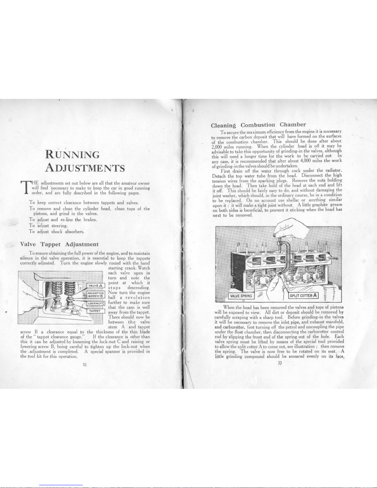
To ensure obtaining the full power of the engine, and to maintain
silence in the valve operation, it is essential to keep the tappets
correctly adjusted. Turn the engine slowly round with the hand
starting crank. Watch
each valve open in
turn and note the
point at which it
stop s descending,
Now turn the engine
half a revolution
further to make sure
that the cam is well
away from the tappet.
There should now be
between the valve
stem A and tappet
screw B a clearance equal to the thickness of the thin blade
of the" tappet clearance gauge," 11the clearance is other than
this it can be adjusted by loosening the lock-nut C and raising or
lowering screw B, being careful to tighten up the lock-nut when
the .,adjustment is completed. A special spanner is provided in
the tool kit for this operation-
32
I
Cleaning Combustion Chamber
To secure the maximum efficiency from the engine it is necessary
to .remove the carbon deposit that will have formed on the surfaces
of the combustion chamber. This should be done after about
2,000 miles running. When the cylinder head is off it may be
advisable to take this opportunity of grinding-in the valves, although
this will need a longer time for the work to be carried out In
any case, it is recommended that after about 4,000 miles the war k
of grinding-in the valves should be undertaken.
First drain off the water through cock under the radiator,
Detach the top water tube from the head. Disconnect the high
tension wires from the sparking plugs. Remove the nuts holding
down the head. Then take hold of the head at each end and lift
it off: This should be fairly easy to do, and without damaging the
joint washer, which should, in the ordinary course, be in a condition
to be replaced. On no account use shellac or anything similar
upon it: it will make a tight joint without. A little graphite grease
on both sides is beneficial, to prevent it sticking when the head has
next to be removed.
When the head has been removed the valves and tops of pistons
will be exposed to view. All dirt or deposit should be removed by
carefully scraping with a sharp tool. Before grinding-in the valves
it will be necessary to remove the inlet pipe, and exhaust manifold,
and carburetter, first turning off the petrol and uncoupling the pipe
under the float chamber, then disconnecting the carburetter control
rod by slipping the front end of the spring out of the hole. Each
valve spring must be lifted by means of the special tool provided
to allow the split cotter A to come out, see illustration; then remove
the spring. The valve is now free to be rotated on its seat. " A
little ~rinding compound should be smeared evenly on its f~ce,
II

~
RUNNING
ADJUSTMENTS
THE adjustments set out below are all that the amateur owner
will find -necessary to make to keep the car in good running
order, and are fully described in the following pages.
To keep correct clearance between
To remove and clean the cylinder
pistons, and grind in the valves.
To adjust and re-line the brakes.
To adjust steering.
To adjust shock absorbers.
tappets and valves.
head, dean tops of the
~Valve AdjustmentTappet
To ensure obtaining the full power of the engine, and to maintain
silence in the valve operation, it is essential to keep the tappets
correctly adjusted. Turn the engine slowly round with the hand
starting crank. Watch
each valve open in
turn and note the
point at which it
stops descending,
Now turn the engine
half a revolution
further to make sure
that the cam is well
away from the tappet.
There should uow be
between the valve
stem A and tappet
screw B a clearance equal to the thickness of the thin blade
of the" tappet clearance gauge," 11the clearance is other than
this it can be adjusted by loosening the lock-nut C and raising or
lowering screw B, being careful to tighten up the lock-nut when
the ..adjustment is completed. A special spanner is provided in
the tool kit for this operation-
32
Cleaning Combustion Chamber
To secure the maximum efficiency from the engine it is necessary
to remove the carbon deposit that will have formed on the surfaces
of the combustion chamber. This should be done after about
2,000 miles running. When the cylinder head is off it may be
advisable to take this opportunity of grinding-in the valves, although
this will need a longer time for the work to be carried out In
any case, it is recommended that after about 4,000 miles the wor k
of grinding-in the valves should be undertaken.
First drain off the water through cock under the radiator,
Detach the top water tube from the head. Disconnect the high
tension wires from the sparking plugs. Remove the nuts holding
down the head. Then take hold of the head at each end and lift
it oft. This should be fairly easy to do, and without damaging the
joint washer, which should, in the ordinary course, be in a condition
to be replaced. On no account use shellac or anything similar
upon it: it will make a tight joint without. A little graphite grease
on both sides is beneficial, to prevent it sticking when the head has
next to be removed.
When the head has been removed the valves and tops of pistons
will be exposed to view. All dirt or deposit should be removed by
carefully scraping with a sharp tool. Before grinding-in the valves
it will be necessary to remove the inlet pipe, and exhaust manifold,
and carburetter, first turning off the petrol and uncoupling the pipe
under the float chamber, then disconnecting the carburetter control
rod by slipping the front end of the spring out of the hole. Each
valve spring must be lifted by means of the special tool provided
to allow the split cotter A to come out, see illustration; then remove
the spring. The valve is now free to be rotated on its seal..' A
little ~rinding compound should be smeared evenly on its f~ce,
II

Cleaning Combustion Chamber-continued.
and the valve rotated hackwards and forwards, advancing it a step
at short intervals until the pitting is removed. Care should he
taken that none of the compound enters the cylinders, and the
valve and seating should he wiped clean after the operation.
When replacing the head take care to tighten the nuts evenly.
Don't forget, after replacing the head, to refill the radiator.
Adjusting the Brakes
The hand hrake operates on the front wheels and the bot
hrake'on the rear wheels. They require adjusting when the hand
lever can he pulled right hack to the full travel on the'rack, and
when the pedal can he pushed nearly to the floorhoard without
either hrake holding the wheels. The car should never he taken
out when in this condition
hut attended to at once. .
To adjust the hand hrake
pull the lever on ahout o;'e-third
(or to suit driver's reach) of
the total travel provided hy
the rack. Now unlock the
nut B and screw up the
hrake adjusting handle A untiI
the shoes are hard on, the
drum. If the hrake sho~s do
not then ruh on the drum when
the lever is right forward. the
adjustment is correct. See
that the handle is locked again
hy nut B.
To adjust the foot hrake: Under
the car and approximately under
the fuot controls is a wing nut
C. This must he
screwed towards the
front of the engine
until the brakes
go full on when
the pedal is de-
pressed ahout 2 in.
When the pedal is
up, the hrake shoes
should not rub
the rear wheel
drums in which
they operate.
Adjustment of Steering
If after continual use slackness should be felt in the steering.
two adjustments are availahle :-1'0 take up the play in the
column, loosen the nut which tightens the bracket supporting the
steering outer column to the instrument board, unscrew locking peg
" A" and clamping holt .. B." then turn the sleeve" C" with
the special spanner provided for the purpose, until the play has
heen removed. Do not screW the sleeve in t06 tight or the
steering will then become stiff. Having adjusted the sleeve
correctly, 'screw in the locking pcg so that it enters one of the slots
of the sleeve, tighten up the clamping halt, and the supporting
hracket to the instrument hoard. '
,.,'
34
To take up the clearance hetween the worm and worm wheel,
due to wear, slacken the three nuts" 0" holding the cover" E "
to the worm casing, then turn adjusting screw" F .. so as to slightly
draw the cover in the direction of the worm, Care must he taken
that the worm wheel is not hrought too tight into mesh with the
worm or it will make the steering exceedingly hard and stiff. Having
made the adjustment he sure and tighten up the three nuts" D."
Should it he desirahle to remove the steering worm wheel
from the casing, it is only necessary to slacken the "djusting screw
F and remove the three nuts 0 when the cover E can he withdrawn
together with the worm wheel and steering arm, The steering
column H with control rods can he withdrawn hy first removing
control levers K and nut L, then slacken lockiIl~ peg A and
clamping halt B and, unscrew the sleeve C.
35
~
Other manuals for Austin Seven
1
Other Austin Motor Company Automobile manuals

Austin Motor Company
Austin Motor Company FX4R User manual

Austin Motor Company
Austin Motor Company A40 Somerset Sedan Technical specifications

Austin Motor Company
Austin Motor Company A40 Somerset Sedan User guide

Austin Motor Company
Austin Motor Company LANDCRAB 1993 User manual

Austin Motor Company
Austin Motor Company Austin Seven User manual


