Austin Motor Company Austin Seven User manual

~~:!fi~'"
r}~
"" ¥'
" '
"" 'C>,,'
,i,
'iIII""'- '"
,
r~..:,
"if'
J
t
I'
'ill
~~~
.
t
~<,
L:p. I
~'" '6,
;"r
( "
. . ~'
"'.
, ,
.~
9h.
;1;;,
.£."
eft
1= =,'"
'" I!!?t ii,~
f"IiIi ~
~:
e~-
~7.
1\1'
k 'i!"
iiI;i """ "f. '" i!"fiB"
HANDBOOK "
"
"
..
~
..
";;p \'oJ.~
!.. .,'.
" "
..
,""" !::'
""" I>-
" PubuCauorr 619
'" i;i
z iIij
'=
'",
~~
11
,rf ~
,
-,' ~
,
'
,
\,,
_
,(:i~STIN MOTOR C<J.L+,
''
~'" '-, c ~l.
LQliGBRIDGE. nearBJRMINGHAM
."",
f
'f.. ..
i
"..
""
.. .,
;~\ '
""... "'"
""""=
. 01 'fitM'
~ '. ",
'1> """"~""!,,
~. "
...'
~7f
~' ..'
..
"11 "
"'
41t
<, "
"" j
"[
"
..,.
,t!'
".
I
<
#\
'.
i!.f
~
,
""'j
>',
;.j
.\
i
,~I
t
~
)!' f
i1!I
"
11,
,',
"'..,
"'A',i>
-::Ai.
..
~., <'i
~
-
'" ~
~
."
..~ '
t",-,
~, " "f
~~'f!f.' V
'*~

~e .,
I!" , .
a
n
/lS,l;e
!1,~
\
!~i
'\lI.
~"
!~
\J' w
"0
,I,
-
\j;
\~ .\'"
""
~i
.
.,
.
!fj
\
"
\fil
,I,
m ~
"
.,
HANDBOOK
r'
.
.
PRICE 2/6
17th EDITION
m
THE AUSTIN MOTOR CO. LTD;
LONGBRIDGE, Nr. BIRMINGHAM
T,l,phone> CENTRAL4140, KING'SNORTON541
Td,gmm" '" SPEEDILY,NORTHFIELD." Cod" BENTLEy'S
LONDON SHOWROOMS, REPAIR DEPOT AND HIRE DEPT, :
479-483, Oxford W./
Street,
(NEAR M<RBLE ARCH)
Td,phon" MAYFAIR6230, T,/,gm=, "AUSTlNETTE,LONDON,"
I
fU "f"ro" to thi, boo' 6
--
1
m-
9I
pl"" quo" "" uum'" ...

"~
CONTENTS
AForeword. AMMETER READINGS
ATTENTIONS, Da;!y ..
Weekly
Monthly
Ocea,ional
PAGE
34
12
12
13
13
35
49
41-42
30
44.45
10
6
8.9
15-19
15
17
18.
29
39.40.
25
33
33.37
27-29
8
25,47
31
35
29
26
31.32
22
23.24
20.24
38
14
27
20.21
30
31
39.47
46
42-43
29
51
50
30
39
11
37
THE information coniained in this Handbook is intended
only to guide 'and assist owners or drivers of "Austin
Seven" cars to preserve the car in its proper satisfactory
running condition. This must not be considered as
.
exhaustive or as varying or extending the liability of the
company,' which is limited to the Warranty issued with the
car. Where no information is given for a particular
adjustment, it may be regarded as one which the average
owner would entrust to a garage. When the occasion for
. adjustments of this character arises, the owner should" seek the
aid of an Austin agent. Both owner and agent are encouraged
to call upon the Service Department of the Company for
advice, whether upon management of the car, the effecting
of adjustment, ot methods of repair. Owners need not
suppose that they will have to apply all t~e attentions given
in this book, but careful notice should be taken of the
chapters dealing with maintenance.
BATTERY, The
BODYWORK, CMe of ..
BRAKES, Ad;u,ting the .
BRAKE GEAR, Luh,ication of ..
BRAKES, Re.lining
CAR, Coutml of the
" FeaMe, of the
" The New
CARBURETTER, The..
" Adju",meut of. .
" Slow Runmug of
" " Leakage horn
CLUTCH, Luh,ication of
COMBUSTION CHAMBER, Geaning ..
COOLING SYSTEM
DYNAMO, The
ELECTRICAL EQUIPMENT, The
ENGINE. Lub,ication of
Sta,ting the. .
Two additional publications give hsts and illustrations of
~ll the parts, and their prices, respectively, and the owner should
find'these books helpful for reference.
FAN ..
FRONT AXLE, Lub,ication of ..
FUSE, Acrion of the
GEARBOX, Lub,icatiou of
GREASE GUN, How to u,e the
HUBS (Fmnt aud Rea,), Lubrication of
IGNITION, Fault, iu
" Timing
" Sy,tern, The
LAMPS. CMe of
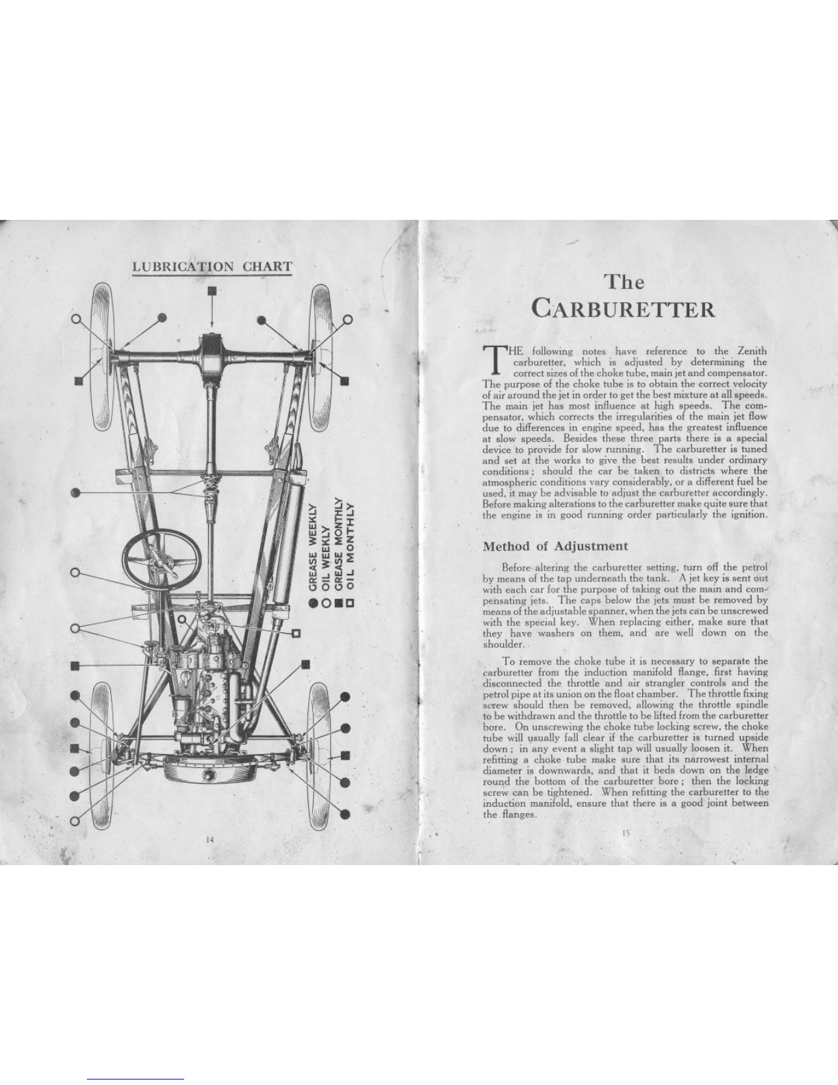
LUBRICATION CHART
LUBRICANTS. Choice of
MAGNETO, Lubricariou of
REAR AXLE. Lub,ication of
ROAD SPRINGS, Lubrication of
RUNNiNG ADJUSTMENTS..
SHOCK ABSORBERS, Adju,trnent of ..
STEERING. Adju,tment of
STEERING GEAR, Lubrication of
TOOLS, Supplied
TYRES. The..
.UNIVERSALJOINT. Lub,ication of
VALVE TAPPETS. Adjmtrnent of
WHEEL. Cbanging a
WIRING. Illu,"ation of
Many of the adjustments and attentions described in the
following pages are included in the" . Austin Seven' Schedule
of Charges fot Repairs." The Company is confident that
owners will find it to their own benefit to make the fullest use
of this standard price repair and maintenance service, which it
is a function of all Austin Agents to offer (see page 19).
IMPORTANT.--See special note on page 52, with
reference to accessories and equipment not manufac-
tured by the Austin Motor Co. Ltd.
February. 1928.
23
j A
""l1li
The ';AUSTIN SEVEN"
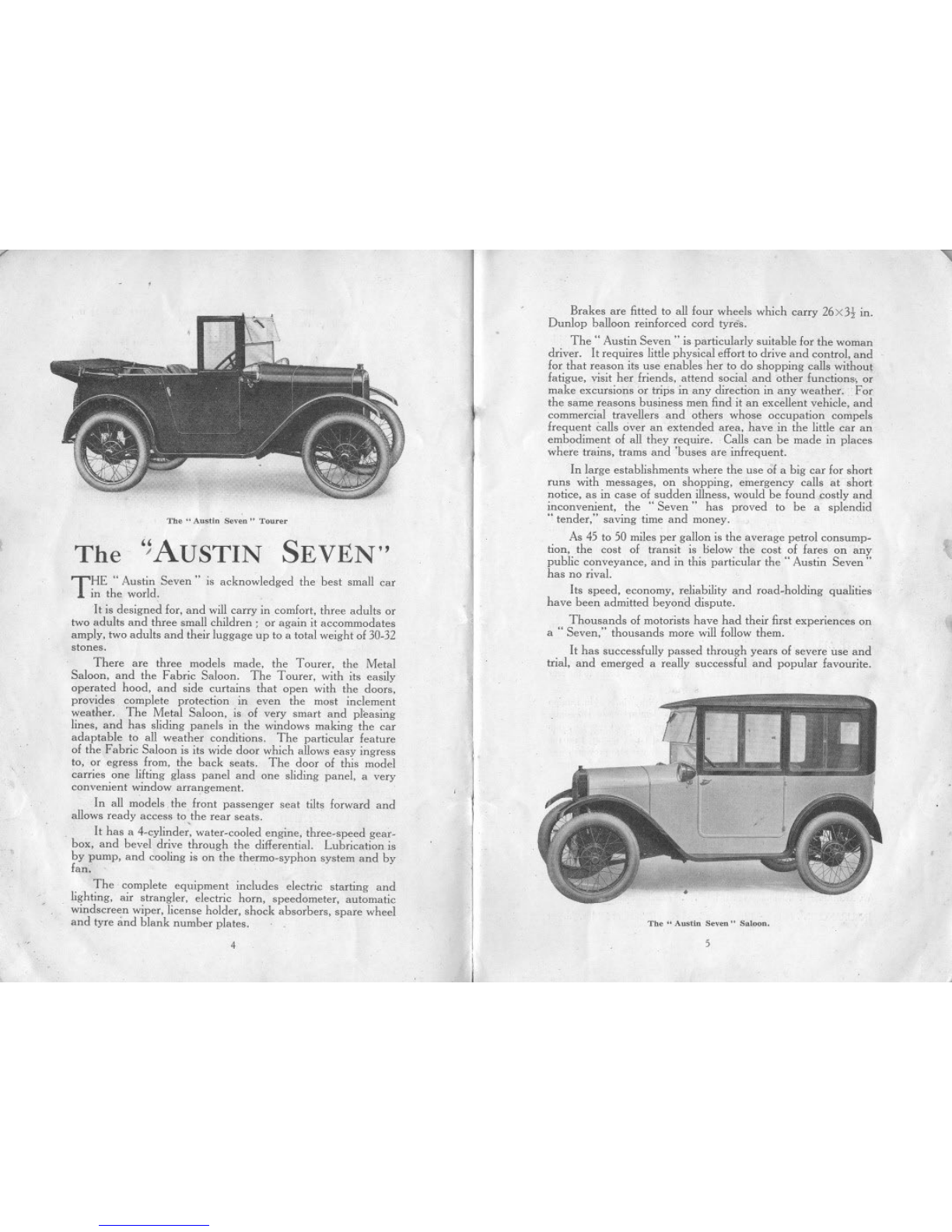
Brakes are fitted to all four wheels which carry 26 X3t in.
Dunlop balloon reinforced cord tyres.
. The" Austin Seven" is particularly suitable for the woman
driver. It requires little physical effort to drive and control, and
for that reason its use enables. her to do shopping calls without
fatigue, visit her friends, attend social and other funciions., or
make excursions or trips in any direction in any weather. For
the same reasons business men find it an excellent vehicle, and
commercial travellers and others whose occupation compels
frequent calls over an exterided area, have in the little car an
embodiment of all they require. Calls can be made in places
where trains, trams and 'buses are infrequent.
In large establishments where the use of a big car for short
runs with messages, on shopping, emergency calls at short
notice, as in case of sudden illness, would be found costly and
inconvenient, the" Seven" has proved to be a splendid
.. tender," saving time and money.
As 45 to 50 miles per gallon is the average petrol consump-
tion, .the cost of transit is below the cost of fares on any
public conveyance, and in this particular the" Austin Seven"
has no rival.
Its speed, economy, reliability and road-holding qualities
have been admitted beyond dispute.
Thousands of motorists have had their first experiences on
a .. Seven," thousands more will follow them.
It has successfully passed through years of severe use and
trial, and emerged a really successful and popular favourite.
The" Au,tln Seven" Tourer
THE" Austin Seven" is acknowledged the best small car
in the world.
It is designed for, and will carry in comfort, three adults or
two adults and three small children; or again it accommodates
amply, two adults and their luggage up to a total weight of 30-32
stones.
There are three models made, the Tourer, the Metal
Saloon, and the Fabric Saloon. The Tourer, with its easily
operated hood, and side curtains that open with the doors,
provides complete protection in even the most inclement
weather. The Metal Saloon, is of very smart and pleasing
lines, and has sliding panels in the windows making the car
adaptable to all weather conditions. The particular feature
of the Fabric Saloon is its wide door which allows easy ingress
to, or egress from, the back seats. The door of this model
carries one lifting glass panel and one sliding panel, a very
convenient window arrangement.
In all models the front passenger seat tilts forward and
allows ready access to ,the rear seats.
It has a 4-cylinder, water-cooled engine, three-speed gear-
box, and bevel drive through the differential. Lubricationis
by pump, and cooling i. on the thermo-syphon system and by
fan.
The complete equipment includes electric starting and
lighting, air strangler, electric horn, speedometer, automatic
windscreen wiper, license holder, shock absorbers, spare wheel
and tyre and blank number plates.
4
The" A.-tin Seven" Satoon.
5
,
7'
DIMENSIONS
,ENGINE
STARTER.
CLUTCH .
GEARBOX.
REARAXLE .
SPRINGS.
STEERING
FRONT AXLE'
BRAKES
WHEELS
CONTROLS
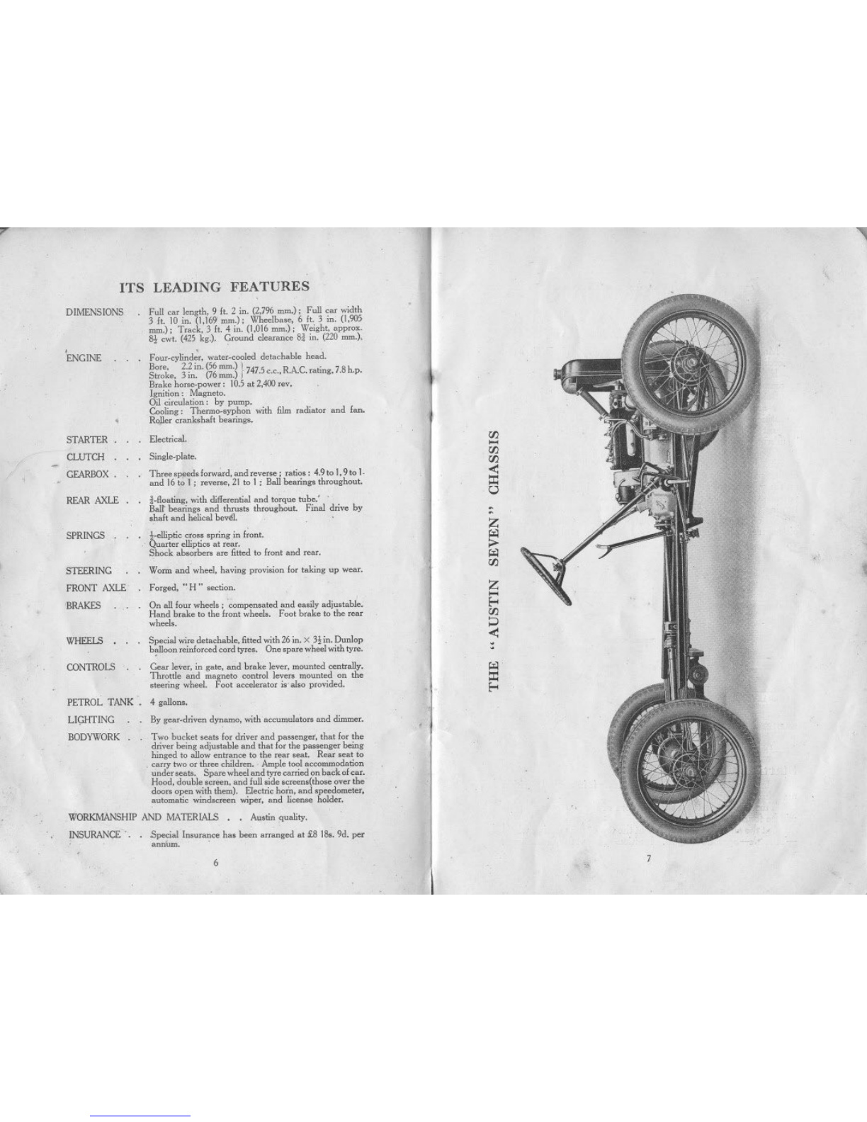
ITS LEADING FEATURES
.
. Full ca<length. 9 It. 2 ;u. (2,796 mm.); Full ca. ,,;dth
3 ft. ID ;u. (1.169 mm.); Wheelba,e, 6 ft. 3 ;u. (1,905
mm.); Tmck, 3 ft. 4 m. (1.016 mm.); We;ght, appmx.
8j; cwt. (425 kg.). G.ouud clea.auce S. iu. (220 mm.),
. Fom.cylinde~, wate..cooled detachahIe head.
Bo.e, 2.2 in. (56mm.) 17475 RAC '7Sh
Stmke, 3 in. (76mm.) f. C.C., . . . mtmg,. .p.
Bmke hom.powe.: 10.5at 2,400 .ev.
Ignihon: Magneto.
Oil cimulahon: by pump.
Coohng: Tbenno.,ypbon ,,;th film mdiato. and lau,
Roller cmnk,halt bearing',
. Electrical.
. Single.plate.
. Tb.ee,peed,fm"Wa.d,and.evem; mho" 4.9to1,9to 1.
and 16to I ; .eve..e, 21to I ; Ballbearing, thwughout.
. ..floahng, ,,;th diffe.enhaland to.que tube:
Ballbeariug, aud tbm,t, tb.oughout. Fmal drive by
,halt aud hehcalb~.
,.eIhPhc cm" 'pring in fwnt.
. Qua.te. eIhPh'" at .ea..
Shock ab,o.be" a.e fitted to [mnt and .ea..
Wonn aud wheel, having pwvi,ion 1o. taking up wea..
Fo.ged, .. H" ,echon.
. I
. On all lom wheel,; compen,ated and ea,ily adju,table.
Hand hmke to the Imnt wheel,. Foot bmke to the .ea'
whee]"
Special ,,;.e detachahle, fitted ,,;th 26 m. X 3, ;n. Dunlop
b~oon .einfo.ced co.d ""e,. One 'pa.. wheel ,,;th ty.e.
Gea. leve., in gate, aud bmke leve., mounted cen"ally.
Thmttle and magneto con"ol lev.., mounted on the
"eering wheel. Foot accelemto. i,' aI,o pmvided.
PETROL TANK. 4 gallon,.
LIGHTING
BODYWORK.
By gea..driven dynamo, ,,;thaccumnlato.. and dimm...
Two bucket ,eat, 1o. drive. and pa"engei, that £0. the
drive. being adju,tahle and that 1o. the pa"enge. bemg
hinged to allow en"auce to the .ea. ,eat. Rea. ,eat to
. ca"y two°, th.ee child..n. . Ample tool accommodahon
unde. ,ea". Spa.e wheel and ty.. "",ried onback ofea..
Hood, double ,aeen, aud lull side ween,(tho,e ove. the
doo.. open ,,;th them). Electric horn, and ,peedomete.,
automahc ,,;nd,«een ,,;pe., and hceme holde.,
WORKMANSHIP AND MATERIALS, , AU'hnquahty.
INSURANCE' . . Special Imu.ance has been a"anged at £8 IS,. 9d. p..
annum. .
6
"
r/]
~
r/]
r/]
<:
::.:
0
"
~
z
f;I;1
;>
f;I;1
r/]
z
...
Eo<
r/]
~
<:
~
f;I;1
::.:
Eo<
,7
7' ,),
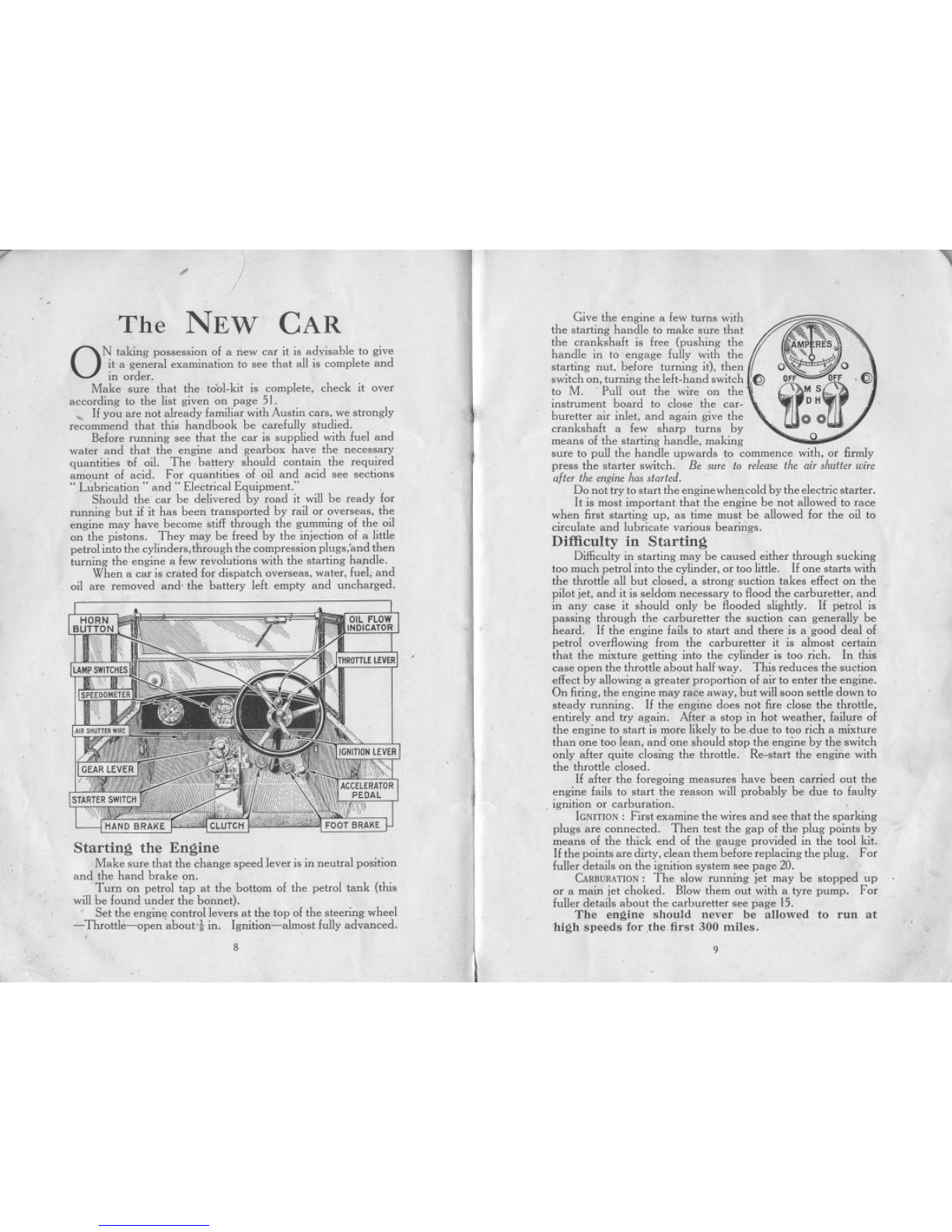
TheNEW CAR Give the engine a few turns with
the starting handle to make sure that
the crankshaft is free (pushing the
handle in to engage fully with the
starting nut, before turning it), then
switch on, turning the left-hand switch I:~
to M. Pull out the wire on the'
instrument board to close the car-
buretter air inlet, and again give the
crankshaft a few sharp turns by
means of the starting handle, making
sure to pull the handle upwards to commence with, or firmly
press the starter switch. Be sure to release the air shutter wire
after the engine has started.
Do not try to start the engine when cold by the electric starter.
It is most important that the engine be not allowed to race
when first starting up, as time must be allowed for the oil to
circulate and lubricate various bearings.
Difficulty in Starting
Difficulty in starting may be caused either through sucking
too much petrol into the cylinder, or too little. If one starts with
the throttle all but closed, a strong suction takes effect on the
pilot jet, and it is seldom necessary to flood the carburetter, and
in any case it should only be flooded slightly. If petrol is
passing through the carburetter the suction can generally be
heard. If the engine fails to start and there is a good deal of
petrol overflowing from the carburetter it is almost certain
that the mixture getting into the cylinder is too rich. In this
case open the throttle about half way. This reduces the suction
effect by allowing a greater proportion of air to enter the engine.
On firing, the engine may race away, but will soon settle down to
steady running. If the engine does not fire close the throttle,
entirely and try again. After a stop in hot weather, failure of
the engine to start is more likely to be due to too rich a mixture
than one too lean, and one should stop the engine by the switch
only after quite closing the throttle. Re-start the engine with
the throttle closed.
If after the foregoing measures have been carried out the
engine fails to start the reason will probably be due to faulty
.ignition or carburation.
iGNITION: First examine the wires and see that the sparking
plugs are connected. Then test the gap of the plug points by
means of the thick end of the gauge provided in the tool kit,
If the points are dirty, clean them before replacing the plug. For
fuller details on the ignition system see page 20.
CARBURATION:The slow running jet may be stopped up
or a main jet choked. Blow them out with a tyre pump. For
fuller details about the carburetter see page 15.
The engine should uever he allowed to run at
high speeds for the. first 300 miles.
9
ON taking possession of a new car it is advisable to give
it a general examination to see that all is complete and
in order. .
Make sure that the tool-kit is complete, check it over
according to the list given on page 51.
, Ifyou are not already familiar with Austin cars, we strongly
recommend that this handbook be carefully studied.
Before running see that the car is supplied with fuel and
water and that the engine and gearbox have the necessary
quantities bf oil. The battery should contain the required
amount of acid. For quantities of oil and acid see sections
.. L~brication .. and" Electrical Equipment." .
Should the car be delivered by road it will be ready for
running but if it has been transported by rail or overseas, the
engine may have become stiff through the gumming of the oil
on the pistons. They may be freed by the injection of a little
petrol into the cylinders, through the compression plugs,'and then
turning the engine a few revolutions with the starting hapdle.
When a car is crated for dispatch overseas, water, fuel, and
oil are removed and- the battery left empty and uncharged.
Starting the Engine
Make sure that the change speed lever is in neutral position
and the hand brake. on.
Turn on petrol tap at the bottom of the petrol tank (this
will.be found under the bonnet). .
., Set the engin, control levers at the top of the steering wheel
~Throttle-open abou\'i in. Ignition-almost fully advanced.
8
'" ~
CONTROL OF THE CAR
".
CHANGING A WHEEL
The Spare Wheel
Setting of Control Levers
AFTER hav:ng started the engine, keep the jgnition lever in
f-\. the advanced position; should the engine commence to
" rumble" or run roughly, retard the lever, but advance
it again as soon as the load on the engine is lessened. The
" gas" lever should be set generally for slow running and the
speed of the car controlled by the accelerator pedal.
Changing Gear
Double declutching will be found the best method of gear
changing on the" Austin Seven" and should be adopted
straight away. It will be understood that when changing up the
foot should be taken off the accelerator pedal, and that when
changing to a lower gear it should be held down. The car should
be well accelerated on each speed when changing up. and a
deliberate pause should be made with the gear lever in neutral
position and with the clutch in whether chang;ng up or down.
The catch below the knob of the gear lever must be raised to
allow the reverse gear to be engaged. ,
Always change gear early on a hill; never allow the eng;ne
to labour in any gear and expect it to pick up speed on changing
into a lower one when the car
has nearly stopped.
Keep the foot off the clutch
pedal except in heavy traffic.
Even then, do not allow the
weight of the foot to be taken
by the pedal.. The slipping
of the, clutch caused by this
practice heats and wears it
badly. '
When descending a long
hill, supplement the action of
the foot-brake at intervals by
the use of the hand-brake for
brief periods. It ,is often
advisable to engage one of the lower gears befo):.e commencing
a steep descent, with throttle closed. When using the brake,
keep the clutch in, disengaging it at the last moment if stopping
,the car.
The driving seat of the" Austin Seven .. is adjustable for
position and tlUs convenience should be taken advantage of so
as to obtain the greatest comfort.
"..
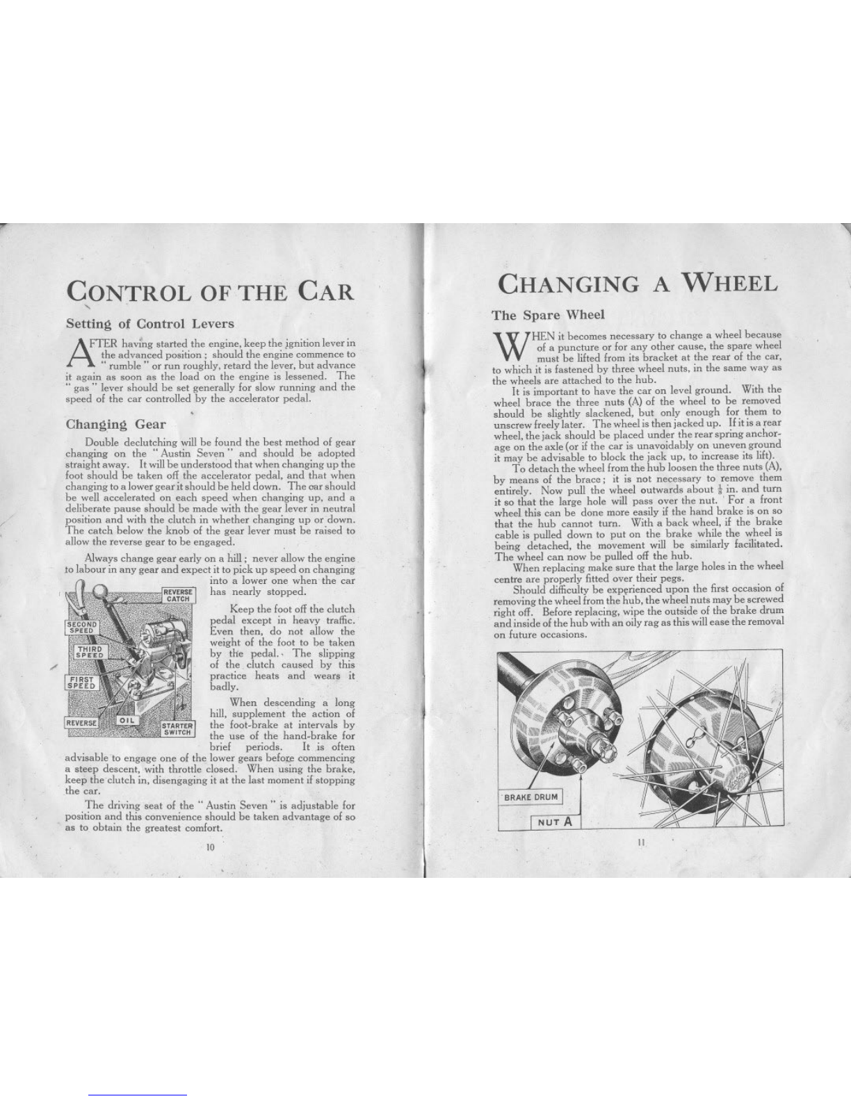
WHEN it becomes necessary to change a wheel because
of a puncture or for any other cause, the spare wheel
must be lifted from its bracket at the rear of the car,
to which it is fastened by three wheel nuts, in the same way as
the wheels are attached to the hub.
It is important to have the car on level ground. With the
wheel brace the three nuts (A) of the wheel to be removed
should be slightly slackened, but only enough for them to
unscrew freely later. The wheel is then jacked up. If it is a rear
wheel, the jack should be placed under the rear spring anchor-
age on the axle (or if the car is unavoidably on uneven ground
it may be advisable to block the jack up, to increase its lift).
To detach the wheel from the hub loosen the three nuts (A),
by means of the brace; it is not necessary to remove them
entirely. Now pull the wheel outwards about iin. and turn
it so that the large hole will pass over the nut. ' For a front
wheel this can be done more easily if the hand brake is on so
that the hub cannot turn. With a back wheel, if the brake
cable is pulled down to put on the brake while the wheel is
being detached, the movement will be similarly facilitated,
The wheel can now be pulled off the hub.
When replacing make sure that the large holes in the wheel
centre are properly fitted over their pegs.
Should difficulty be exp~rienced upon the first occasion of
removing the wheel from the hub, the wheel nuts may be screwed
right off. Before replacing, wipe the outside of the brake drum
and inside of the hub with an oily rag as this will ease the removal
on future occasions.
~;
NUT A
10 11.

Daily Attentions
I. Examine water level in radiator and
fill up to' within 2 in. of the top. Always
use the strainer when re-filling as
dirty water will cause the radiator
film to become choked.
2. Examine oil level in the crankcase
and add more oil if necessary. The
tell-tale dipper rod indicates the level
of the oil (see illustration, page 27).
3. Fill up the petrol tank if necessary.
Care should be exercised when filling
the tank not to spill the. petrol over
the engine.
r
~.
,~
.
ON this and the opposite page is a handy
summary 01 all the attentions described in
this handbook. The attentions under.. the
daiIY, weekly, and monthly headings are based on
the assumption that the maximum mileage per
week does not exceed 300. .
The occasional attentions should not be neglected
if the car is to continue to run efficiently. When
relerring to the attentions below, see the lubrica-
tion chart on page 14.
PERIODICAL
ATTENTIONS
Weekly Attentions
I. With the grease. gun charge-
Front spring shackle pins (4).
Rear spring pins (2).
Front wheel swivel pins (2).
Steering cross tube (2):
2. Oil the following-
Handbrake gear.
Pedal gear and jaw joints.
Engine control and ball joints.
Clutch release ring.
Rear brake cam spindles (2).
Steering side tube joints (2).
3. Examine both sets of brakes, and
if necessary.
12
,
4. Inject high speed grease (such as
Messrs. Stern's" Diamol ") into the
universal joint at the rear end of the
propeller shaft using the special adapter
on the grease gun, and yellow grease into
the front end of the torque tube.
5. Test the tyres for correct pressure and
examine them for cuts (see page 50).
Monthly Attentions
I. Examine the oil level in the gearbox
which should contain two-thirds of
a pint, or measure 2-2t in. deep.
2. Charge the back axle case with a gunful
of grease and oil mixed half and half,
using the special adapter on the grease gun.
3. Fill all the hubs with grease, as
described on pages 3I and 32.
4. Charge with grease the steering worm
case through the nipple.
5. Examine the battery and see that the
connections are tight. For details see
page 35.
6. Give a charge of grease to the nipple
on the fan spindle.
J
1
'" ..
Occasional Attentions
adjust
Examine all bolts and nuts. such ris road spring clips,
cylinder head nuts, wheel nuts (these three especially when the
car is new), examine other parts such as steering connections,
the radius rod anchorage below the gearbox, and the torque
tube socket, neglect 01 which points might be lollowed by an
expensive repair, and the inability to use the car lor a lengthy
period.
Occasionally clean the petrol filler and float chamber
strainers, the radiator filler strainer, the oil filler strainer, and the
oil reservoir gauze (when the engine oil can be changed); also
ensure that the oil jets, under the plugs on the crankcase, are
clean. Drain the gearbox and refill with fresh oil (i pint).
Flush the. radiator through. Clean the magneio dis-
tributor, and the contact breaker points (adjust the latter),
the dynamo and starter commutators. Clean and lubricate
the shock absorbers, adjust the tappets, and the fan belt,
decarbonize the engine and grind-in the valves. Check the
alignment of the Iront wheels. For details 01 these attentions
refer to the pages tha t follow. .
13
"'"
..
LUBRICATION CHART
.
;,
~ ~~
i5 z:I
...~ol-
~:.:::i:Z
... 0
"""
U1 :>. U1 0:;
«:>«
"' "'...1
~-~-
0000
808C
14
/!
(
,
,
,.,
,"
"";.
~'
"
-
The
CARBURETTER
,THE following notes have reference to the Zenith
carburetler, which is adjusted by determining the
correct sizes of the choke tube, main jet and compensator.
The purpose of the choke tube is to obtain the correct velocity
of air around the jet in order to get the best mixture at all speeds.
The main jet has most influence at high speeds. The com-
pensator, which corrects the irregularities of the main jet flow
due to differences in engine speed, has the greatest influence
at slow speeds. Besides these three parts there is a special
device to provide for slow running. The carburetler is tuned
and set at the works to give the best results under ordinary
conditions; should the car be taken to districts where the
atmospheric conditions vary considerably, or a different fuel be
used, it may be advisable to adjustthe carburetter accordingly.
Before making alterations to the carburetler make quite sure that
the engine is in good running order particularly the ignition.
Method of Adjustment
Before- altering the carburetter setting, turn off the petrol
by means of the tap underneath the tank. A jet key is sent out
with each car for the purpose of taking out the main and corn'
pensating jets. The caps below the jets must be removed by
means of the adjustable spanner, when the jets can be unscrewed
with the special key. When replacing either, make sure that
they have washers on them, and are well down on the
shoulder. . .
To remove the choke tube it is necessary to separate the
carburetter from the induction manifold flange, first having
disconnected the throttle and air strangler controls and the
petrol pipe at its union on the float chamber. The throttle fixing
screw should then be removed, allowing the throtlle spindle
to be withdrawn and the throttle to be lifted from the carburetler
bore. On unscrewing the choke tube locking screw, the choke
tube will usually fall clear if the carburetter is turned upside
down; in any event a slight tap will usually loosen it. When
refitting a choke tube make sure that its narrowest internal
diameter is downwards, and that it beds down on the ledge
round the bottom of the carbutetler bore; then the locking
scre~ can be tightened. When refitting the carburetter to the
induction manifold, ensure thal there is a good' joint between
the. flanges.
15 ,
~ ,

r
{
Poor Acceleration
When picking up is bad, or when it is impossible to obtain
a sharp acceleration no matter what size of compensator is used,
the choke tube is too large. The tests for" pick-up" should
be made on the level. Let the car run at a good .speed, slow
down slightly; then press the accelerator down sharply as far
as it will go. The car should then quickly pick up its previous
speed without hesitation.
If, instead of accelerating, the engine stops, try larger
compensators. If, in spite of this, the picking up is not good,
the choke tube is too large, in which case fit another, one or two
millimetres smaller, and try again until the acceleration is perfect.
AI. HOLE
CHOKE
TUBE
MAINJET
COMPENSATING JET
CAPS
Tb. Z.nUh ca,bu,""", type 2>F. Th. ~tand..d .e"lng I.,
choke tnb. 15, main Jet 70, camp.n.atlng Jet 75, .Inw ,unnlng
tnbe 26.35.
Lack of Speed
With too small a choke tube the pick-up is excellent but
the speed attained on the level with the accelerator right down
is insu/ficient-a larger choke tube is then fitted, and the jet
altered proportionally, when the tests are continued until a
satisfactory maximum speed is attained.
Choking and" Hunting"
To ascertain the correct size of the main jet, the test is also
made on the level at high speed. A jet ",hich is much too large
causes choking, and the engine often runs jerkily and hunts.
The petrol consumption is also excessive. The jet that gives the
greatest speed on the level is chosen. If two jets give an equal
speed, choose the smaller on the score of economy.
16
.
~
No Power
When the car gets away badly, and popping.back occurs
in the carburetter when accelerating, the main jet is too small.
This popping.back occurs at irregular intervals, and the engine
has little power and cannot drive the car at a high speed. Fit
larger jets until these explosions in the inlet pipe disappear and
then fest until the right jet has been found, as indicated in
previous paragraph. .
The popping-back may also be due to air leaking into the
induction pipe through joints which are not air-tight, to-leakage
at the extra air valve, or to'thevalves not closing properly. Test
the tappet clearances by the thin blade of the sparking plug
and tappet clearance gauge. In some cases popping back is
due to the engine being cold, and will cease when it has been
running for a little time. .
I
i
Irregular Firing
The trials of different compensators ~hould take place
up an incline, with the engine driving the car at a speed it can
scarcely maintain, say 300 to 500 Lp.m. The compensat~r is
too large when the engine at this speed runs with an irr~gular,
jerky motion; the hunting which takes place at high speed in
the case of too large a main jet is found at low speeds with too
large a compensator. The size of the compensator is decreased'
until all the cylinders fire evenly and the exhaust is quite regular.
As in the case of the main jet, if two compensators gi):'e equal
results. choose the smaller on the score of economy. The
compensator plays a great part in the picking-up, but when the
size of the former is determined according to the above method,
it is generally suitable for an excellent acceleration.
w
I
Slow Running Device
Nofe that too much petrol for slow running causes choking
and hesitation in pick-up. A want of petrol, on the other hand,
causes a loss of power and misfiring at the same time. It i.
therefore necessary to regulate the slow running as carefully ';S
possible. By first releasing the lock nut and then turning the
knurled screw B to the right a gre...ter flow of petrol.is obtained,
while it can be cut down by'furning the screw to the left.
This device can be drawn out after releasing the lock.nut ,
and slackening the round. headed screw A on the side. It is
possible to unscrew the lower half C, from the upper with a pair
of pliers. in order to see if it is clear.
17
--., I
"
There are other factors quite apart from the carburetter
which have great influence on slow running (slow running when
the engine is out'of gear and the car is stationary).
These factors are:-
Joints not air-tight. Valve guides worn. Valves not
seating. 19nition too much advanced.
Engine Misfires and Stops
In tests made as in the last instance. the engine misses fire
now and again, the transmission receives jerks, ami the engine
finally stops. In this case fit a larger compensator until the
engine runs regularly. '
,I
The Float Chamber
Petrol leakage from the float chamber may be due to the caps
under the jets not being tight..or a leaking petrol pipe union.
If no leakage seems possible' at these points, suspect float
chamber derangement, which is causing petrol to overflow, tbe
jets. It may be that the float control is out of adjustment, the
float may be perforated, or the needle not seating properly
owing to dirt on the needle seating. The remedy for the last
mentioned defect is obvious; the first two defects should be
left to an expert to remedy. When replacing the float chamber
cover, ensure that the needle has entered its seating, and is free
to be moved by the float; also that the cover beds down
properly, then secure it with the clip.
w..."
Petrol Flow
If the petrol supply from the Autovac is unrestricted yet
difficult starting points to insufficient petrol. there is a restridion
somewhere in the carburetter. First, see that the air vent in the
float chamber cover, under the retaining chp, is clear. Should
it be so, the next point to examine is,the filter below the float
chamber, and the passage from it to the needle seating. Access
to this filter is given by removing the petrol pipe union and un-
screwing the petrol inlet nut, on the bottom of the float chamber.
,The slowrunning tube and jet maybe stopped up. Remove
the slow running tube bodily, having loosened its locking screw.
In the bottom of the tube is a small filter which can be prised out
and cleaned. The bottom portion of the tube, comprising the
jet, may be then unscrewed from the top portion, and the jet
cleaned if stopped up; two flats on the jet allow a small spanner
to be used to unscrew it. Lastly the compensating or main
jets may be choked. Remove them and clear them. Never
insert anything in any of the jets; always blow through to clear
them; a tyre pump can be used if desired. When refitting the
slow running tube ensure that it beds down to its collar at the
top, with the small projection under the collar fitting the groove
in the carburetter casting; then tighten the locking screw.
18
"
Difficulty in Starting
This may be due to several cause'~
Float chamber air vent stopped up (see previous page),
Slow running tube stopped up (see previous page).
Plug points too far apart. See" Ignition System."
Ignition lever badly placed. See next.paragraph.
Jets choked up (see previous page),
,With variable ignition there is generally" particularly
favourable setting for easy starting. One who is continually
using a car soon recognises this position.
,.
STANDARD REPAIR
CHARGES
THE following adjustments and repairs described in this
,handbook are included in the" Austin Seven" Schedule
, ' 'of Charges for Repairs, which quotes over ninety prices
for repairs to the ".Austin Seven." Owners will find it to their
advantage to have their car adjustments and repairs e!fected
by Austin agents at these standard prices.
Creasing spring shackles, steering and brake, and other
small connections. .
,Ditto, but including rear axle, universal joint, steering box
and front hubs.
Taking down, cleaning and greasing all road springs,
reassembling with new bolts and bushes where required.
Dismantling shock absorbers, then cleaning and adjusting
and refixing. "
Adjusting and compensating brakes.
Relining brakes, front or rear.
Removing cylinder head; decarbonising and grinding in
"valves: adjusting tappets and tuning-up engine on the
road.' ' ,
Fitting new cylinder head and/or gasket.
Adjusting valve tappets, cleaning and adjusting contact
breaker, distributor and sparking plugs; cleaning out
carburetter jets.
Fitting new valves.
Removing base chamber, cleaning oil filter, exarmnmg
interior of engine, and refilling with new oil.
Removing dynamo from car; cleaning and adjusting,
examining battery and connections, and refilling battery
with acid as required.
Tracking up front wheels by adjusting length of cr~ss
steering tube.
Adjusting mesh of steering worm and wheel.
19
~
.
"
..~
I
I
~
I '..
7'
The IGNITION SYSTEM
THE following remarks are common to
.
all magnetos other
than the M.L., particulars of which are given
overleaf.
The magneto requires very little attention, and the only -
adjustment necessary is that of the gap between the platinum
points (A and B) of the contact breaker. The correctness of this
gap is tested by the gauge on the side of the magneto spanner.
Too great a gap will advance the timing and cause wear on the
p,oints. The adjustment is made by turning the screw (B) after
releasing the lock.nut (C). Tighten the lock-nut again when
the adjustment has been completed. Keep the points free from
oil. Should they become ragged have them trimmed lightly
with a dead smooth file by a skilled man.
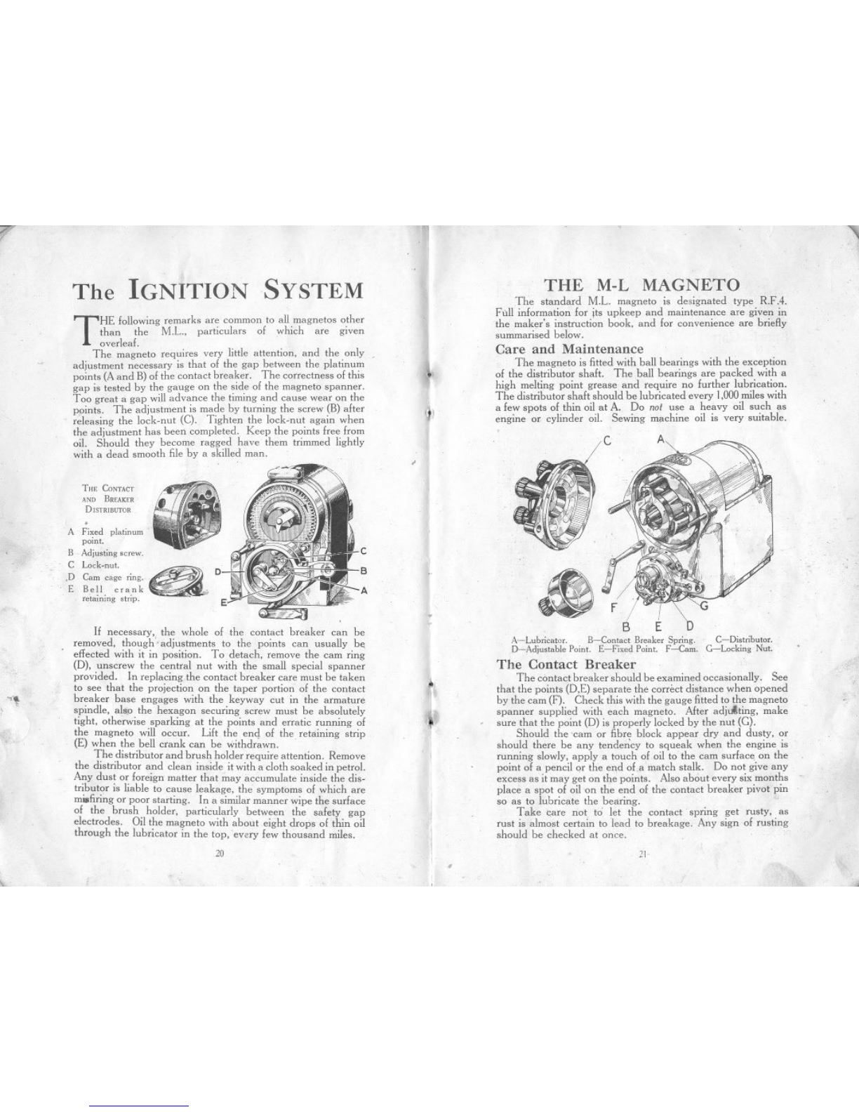
THE CoNTACT
AND BREAKER
DISTRIBUTOR
.
A Fixed platinum
point.
B Adjusting mew,
C Lock.nut.
.D Cam cage ring.
E Bell crank
retaining ",ip. aB
A
E
.."
If necessary, the whole of the contact breaker can be
removed, though" adjustments to the points can usually be
.effected with it in position. To detach, remove the cam ring
(D), unscrew the central nut with the small special spanner
provided. In replacing the contaci breaker care must be taken
to see that the projection on the taper portion of the contact
breaker base engages with the keyway cut in the armature
spindle, also the hexagon securing screw must be absolutely
tight, otherwise sparking at the points and erratic running of
the magneto will occur. Lift the end of the retaining strip
(E) when the bell crank can be withdr~wn. .
The distributor and brush holder require attention. Remove
the distributor and clean inside it with a cloth soaked in petrol.
Any dust or foreign matter that may accumulate inside the dis.
tributor is liable to cause leakage, the symptoms of which are
m.firing or poor starting. In a similar manner wipe the surface
of the brush holder, particularly between the safety gap
electrodes. Oil the magneto with about eight drops of thin oil
through the lubricator in the top, .every few thousand miles.
20
..
1
I
4\
~)
..
.
~
I
"
THE MAGNETOM~L
The standard M.L. magneto is designated type R.FA.
Ftill information for jts upkeep and maintenance are given in
the maker's instruction book, and for convenience are briefly
summarised below.
Care and Maintenance
The magneto is fitted with ball bearings with the exception
of the distributor shaft. The ball bearings are packed with a
high melting point grease and require no further lubrication.
The distributor shaft should be lubricated every 1,000miles with
a few spots of thin oil at A. Do not use a heavy oil such as
engine or cylinder oil. Sewing machine oil is very suitable.
c
B
A~Lubricator. B-Contact B<eaker Spring. C-Di,tributor.
D-Adju,table Point. E-Fixed Point. F-Cam. G-Locking Nut.
The Contact Breaker
The contact breaker should be examined occasionally. See
that the points (O,E) separate the correct distance when opened
by the cam (F). Check this with the gauge fitted to the magneto
spanner supplied with each magneto. After adj,jting, make
sure that the point (D) is properly locked by the nut (G).
Should the 'cam or fibre block appear dry and dusty, or
should there be any tende,{cy to squeak when the engine is
running slowly, apply a touch of oil to the cam surface on the
point of a pencil or the end of a match stalk. Do not give any
excess as it may get on the points. Also about every si." months
place a spot of oil on the end of the contact breaker pivot pin
so as to lubricate the bearing.
Take care not to let the contact spring get rusty, as
rust is almost certain to lead to breakage. Any sign of rusting
should be checked at once.
21
.
r
Do not attempt io run with a very large gap between the
contact points. They wear more rapidly and the machine will
be less efficient. because the armature will not be in the best
position when the circuit is broken.
Spark Gap
Do not use any form of amplifier or spark gap in connection
with the magneto. No improvement will be obtained. and its
use may lead to high voltages and possible breakdown.
I
Insulating Surfaces
As wet and dirt on insulation will often cause leakage and
bad starting. it is advisable to keep the outside of the distributor.
to which the HT. cables are connected, reasonably clean and
free from accumulation of dirt and dust. In addition the
distributor should be removed about every 5,000 miles and the
interior wiped out with petrol and a soft rag. As the R.FA
magneto is of the revolving field type there is no br'lsh holder
and slip ring at the other end of the magneto to require attention
and the whole of the H.T. insulation is exposed when the
distributor block is removed. H the insulation of the distributor
rotor, or the insulating bush. passing through the centre of the
gear wheel. are dirty these should be cleaned. at the same time
care being taken not to damage or break them. When the
distributor cover is removed. examine the carhon brush in the
distributor rotor, making sure that it slides freely. Do not
remove it from its guide unnecessarily, and take care not to
strain the spring.
TROUBLES REMEDIESAND
IRREGULAR firing or faulty ignition may be traceable to
slight defects in the magneto or carburetter. Apartially
choked jet. or an incorrect petrol level, may be the fault.
Air leaks in the induction system are a possible cause of bad
starting and irregular running at low speeds.
For faulty ignition. First examine the sparking plugs and
test the gap of the plug points by means of the thick blade of the
sparking plug and tappet clearance gauge provided in the kit.
H the points are dirty, clean them before replacing. Asudden
failure of the ignition may result from the short circuiting of the
switch cable attached to the terminal on the inspection cover of
the contact-breaker. This can be readily detected by discon-
necting this cable from the terminal, when the en!!iI\~ ~!!Qu!dliie .
properly. .
22
~
--, ~
.TIMING THE IGNITION
t.
~
Should it become necessary to re-time the magneto, it is as
well that the operator should know that the magneto on the
.. Austin Seven" is coupled up to its driving shaft by means of
a patented drive-which provides extremely fine adjustment.
so that the magneto can be correctly timed.
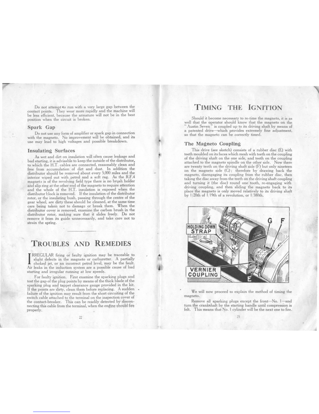
The Magneto Coupling
This drive (see sketch) consists of a rubber disc (E) with
teeth moulded on its faces which mesh with teeth on the coupling
of the driving shaft on the one side, and teeth on the coupling
attached. to the magneto spindle on the other side. Now there
are twenty teeth on the driving shaft side (F) but only nineteen
on the magneto side (G); therefore by drawing back the
magneto. disengaging its cou,pling from the rubber disc. then
taking the disc away from the teeth on the driving shaft coupling
and turning it (the disc) round one tooth. re-engaging with
driving coupling, and then sliding the magneto back to its
place the magneto is only moved relatively to its driving shaft
by I{20th of I/19th ola revolution, or 1{380th.
~
.;
;~:
I
I
I
1
We will now proceed to explain the method of timing the
magneto.
Remove all sparking plugs except the front-,-No. I-and
turn the cranbhaft by the starting handle until compression is
felt. This means that No. 1 cylinder will be the next one to fire.
23
i
rI
Remove the starte~ motor with its casing by unscrewing the"
securing studs, one on each side of the casing, and. lifting the
assembly clear vertically off the locating dowel on the crank-
.case, A line willbe seen on the back of the flywheel, marked...
I and 4 (see illustration on page 29), This line is parallel to the
throws of the crankshaft, and when this line .is verticalitiOo
naturally follows that Nos, I and 4 pistons are at the top of
their stroke. In this case, however, we are only dealing with
No. J. Now turn the flywheel until this line is Iiin. to I! in.
before the top centre. This is the position at which the spark
should take place at the sparking plug, when the ignition is
fully advanced.
Now fully advance the ignition lever at the top of the
steering wheel. Disconnect the contact breaker control and
magneto strap, draw back magneto to disconnect the coupling.
Turn the spindle by hand until the carbon brush of the dis-
tributor is on the segment corresponding to the magneto I~ad of
No. I cylinder, and carefully leave it so that the points of the
contact breaker are just commencing to separate. Thi" is the
position where the spark takes place. .
Now hold the rubber disc in between the driving shaft and
magneto, and slide the magneto towards its place-'-Without
having turned the spindle-leaving just sufficient room for the
rubber disc to be turned round, without being in engagement
on either side. Turn the rubber disc until the teeth on each
side come exactly opposite those they mesh with. Then push
the magneto up into place.
Checking the Timing
If nothing has moved while this latter part of the operation
has been taking place, the magneto should be correctly timed,
but as it is extremely difficult, wiihout making use of the fine
adjustment, to do this, the timing should now be checked.
Turn the engine round two revolutions, bringing l\Jo. 'i
piston into its firing position again, and set the line o~ th';
flywheel. as before described. Check the contact breaker.
If it has not commenced to open, the timing is late. The
timing is advanced by drawing the magneto' back, without
revolving it; detaching the rubber disc from both sets of teeth
and turning it one tooth in the opposite direction to that in which
the magneto revolves-which in this case means turning the top
of the disc towards the operator as he stands at the offside of
the car. This, as before described, will advance the firing
point of the magneto, relative to the driving spindle, 1/380th
of a circle. Check and if still timed late, advance still furth~r.
To retard, the coupling will be turned one or more teelh,
as required, in the opposite direction.
The order in which the cylinders fire is, from the front, 1-3
-4-2. ..
24
....
.~
-The
COOLING SYSTEM
~
~.
THE cooling of the engine is maintained by a capacious
radiator which should be filled, with rain water, if
. available, up to within 2 in. of the top of the filler. The
capacity of the radiator, pipes and cylinder jackets is 9 pints.
In Cold Weather
Care should be taken to see that the water is drained off
completely, for, in case of freezing, it will do harm by lodsing in
small spaces and fracture of the cylinder block may result;. In
Great Britain, th~ climate d?e.s not v'J!Y often call f~r the .cooling
system to be dramed, but It ISwell fa err on the nght sIde and
take due precaution against damage if frost be threatened.
Glycerine mixed with the water will reduce its freezing point
by several degrees. It should be added in the proportion .of
15% to 20%. In cold weather use the Austin raqiator muff.
To prevent the gradual formation of deposits in the cooling
system, with consequent impeding of the circulation, the USe of
hard water should be avoided. Rain-water, syphoned from the
top of the barrel where it is clean, should be used, or, failing
that, water that has been boiled.
I
J
I
tiI
t
Causes of Overheating
Overheating may be attiibuted to one or more of the
following;
Slack fan belt: the belt can be' tightened by turning the
fan spindle in its bracket after /,4osening the clamping-nuts.
Excessive carbon deposit in cylinders. See" Running
Adjustments."
Running with ignition too far retarded.
Using oil of poor quality, or lack of oil in the reservoir.
See" Engine Lubrication." I' .
partial choking of tt;, oil jets. See" Engine Lubrication."
Improper carburetter adjustment, giving a mixture too rich
or too weak. See" The Carburetter." I
Failure of water to circulate, because of choked radiator
tubes, water level below the tops of the radiator tubes, or loss
of water through leakage from connections.
Overcooling is almost as bad as overheating. If the engine
tends to be too cool, use a radiator muff, or possibly, in winter,
the fan belt can be removed without the engine running too hot.
I
*
if
I
'J.
25 ,.
j

;'
The entire circula'ing system should be thoroughly flushed
out occasionally, To do this open the drain tap at the bottom,
place a hose in the filler, and run fresh water through. .
Trouble arising from a damaged radiator generally
necessitates its dismantlirig and despatch to a repair depot.
How To USE THE
GREASE GUN
Screw the handle right out. Unscrew the extension piece
by the knurled nut at the base of the barrel and fill the barrel
with grease; then replace. Give the handle one complete
turn: this fills the telescopic extension piece at the end of the
gun which will project. Now place the end of the gun on the
nipple attached to that part of the car which it is. desired to
grease, and push. The extension piece closes and discharges
the grease into the nipple.
Give the handle another turn and the gun is once more
charged. Continue until the barrel is empty and then refill.
For the rear universal joint and the back axle a special
adapter is used on the gun in place of the standard telescopic
end. This adapter screws into the part to be greased, in place
of the plug. When replacing the plug, do not omit its washer.
It is important not to let dirt get into the adapter which, when
not in use, is screwed onto the side of the gun.
'" /, DON'T!
Don't, pleasedon't-
Don't leave the car in gear with the handbrake off.
Don't make a fast run with the radiator muff down.
Don't fill the radiator with cold water when the engine is hot.
Don't try to turn the engine without first pushing the starting.
handle in to engage fully with the starting nut.
Don't be cruel to the starter if the engine will not fire.
Don't touch the reverse catch when changing gear.
D~n't put an excessive quantity of lubricant in the gear box.
Don't pour oil into the engine with the strainer removed.
Don't forget the ignition switch when starting up.
Don't run the engine in a closed garage. (The exhaust gases
are highly toxic and a very small amount in a restricted
atmosphere will produce grave, if not fatal, results.)
26
'"
";
...
-
i
"
'1.
.
i
~
LUBRICATION
Choice of Lubricants
FOR the engine or gear box use one of the followin.
g oils:-
Stern's" Sternol W.W:' Heavy; Price's" Motor-
ine C:'; Speedwell .. Sans Egal Zero"; .. Triple
Shell"; .. Mobiloil BB:'; .. Speedolene B. Heavy"; T exaco
.. Heavy"; Filtrate" Extra Heavy"; .. Royal Snowdrift 3 .. ;
Wakefield's .. Castrol XL"; and. Duckham's .. Adcol NP 3
and 4:'
Use ordinary" engine" oil in the small can,. and ordinary
yellow grease for greasing.
Both these lubricants can be obtained from any garage or
repair shop.
Use" High Speed" grease for the rear universal joint .of
the drive shaft,
The Engine
When the neW car is sent out the engine and gearbox i.
filled with" Sternol W.W. Heavy" to the proper level. On no
account must different brands of oil be used in the engine at the
same time or mixed in any way. If the oil is too thick it will
tend to clog and carbonise. and if too thin it might lead to
scoring of the pistons and bearings. Assurance that oil is
continuously circulating is given to the driver by means of
the tell.tale button on the instrument board, which protrudes
when the oil is circulating.
.It is essential that all receptacles foroil be kept perfectly
clean. Dirty oil
leads to undue
wear ofall bearings,
or might even clog
up the oiling
system and prevent
it ,,:orking, thus
causmg an engme
seizure and much
troyble and ex.
perise. The oil
filler strainer (A)
is detachable for
cleaning. After the
first 500.800miles
running, drain the
original oil from
/I
"
27
t-
I
the 1<eservairby remaving the plug in the battam, while the
engi~ is hat. Drain the reservair campletely. Never pqur
ail i~t" the engine except thraugh the strainer.
After the first re-filling it is advisable ta change the ail in the
engine entirely alter every 1,200ta 1,500 miles running ar saaner.
Every 2,400-3,000 miles remave the ail r",ervair. The
gauze oil tray will then be accessible lor remaval. Carelully
clean the gauze and remove all dirt Irom inside the reservoir.
and replace them, Carelully remake the jaint with the packing
washer, cavering bath sides '11it with grease. When tightening
up the nuts halding the ail reservoir to the crankcase, do not
pull up ane nut tight, but tighien each nut equally, a little at
a time. See that the draipplug is screwed up tight: then fill the
crankcase with oil to the maximum level as shawn an the
dipper rad, B. Abaut half a gallan will be enaugh ta fill.
Always inspect the level '11'the ail and add, enaugh ta fill,
ta the correct level belore starting an a lang journey.
The ail level shauld nat be allawed to go below'! inch an
the battam '11the.dipper rad. It is advisable ta wipe the dipper J
rod belare taking. the reading '11 the level, and the reading J
shauld anly be taken when the engine is nat running and the
car is an the level ground.
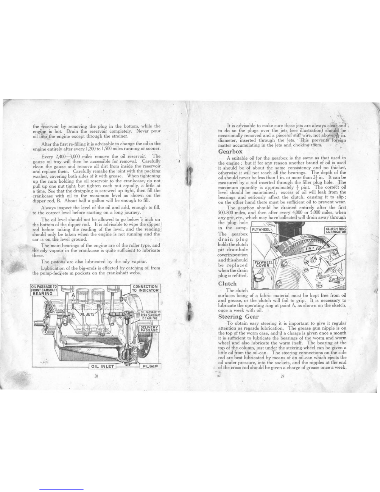
The main bearings '11the engine are '11the roller type, and
the aily vapaur in the crankcase is quite sufficient ta lubricate
these.
The pista';1i' are alsa lubricated by the aily vapour.
L",bricatian 01 the big-ends is effected by catching aillram
the pump-Iedjjets m pockets on the crankshalt webs.
.
.
.."." PUMP
28
~. .',
,. ,
':~~'.
'. "i.
It is advisable ta make sure these jets are always cle~,,~rit.
ta da sa the plugs over the jets (see illustratian) shau!~t pe .
a~casianall'yremavedand a piece:ol stiff wire, nat abo~e~in.
diameter, mserted through the Jets. 1;l)is prevent~ 'Im:elgn
matter accumulating in the jets and chaking.t~m.
Gearbox .'
A suitable aillar the gearbox is the same as that used in
the engine; but il lar any reasan anather brand 01ail is used,
. it should be '11abaut the same cansistency and na thicker,
atherwise it will nat reach all the bearings. The depth 01the
ail shauld never be less than I in. ar mare than 2t in. It can be
measured by a rad inserted through the filler plug hale. The
maximum quantity is appraximately !pint. The correct oil
level shauld be maintained; excess '11ail will leak Iram the
bearings and seriausly affect the clutch, causing it to slip;
an the ather hand there must be sufficient ail ta prevent wear.
The gearbax. shauld be drained entirely alter the lirst
500-800nilles. and then alter every 4.000 ar 5,000nilles. when
any grit, etc., which may have'collected willdrain away'through
the plug hale 's..
in the sump. FLYWHEEL
The gearbax T
drain plug 111/11
halds the clutch 1111<,.
pit drainhale
caverin pasitian
and this shauld
be replaced
when the drain
plug is relitted.'
Clutch
The clutch
surfaces being '11a labric material must be kept free Iram ail
and grease, ar the clutch will lail ta grip. It is necessary ta
lubricate the aperating ring at paint A. as shawn an the sketch,
once a week with ail.
.
J
I
I
I
I
It
Steering Gear
Ta abtain easy steering it is impartant ta give it regular
attentian as regards lubricatian, The grease gun nipple is an
the tap '11the worm case, and il a charge is given ance a manth
it is sufficient to lubricate the bearings '11the worm and warm
wheel and also lubricate the WQ1'mitself. The bearing at the
tap '11the calumn, just under the steering wheel can be given a
little ail Iram the ail.can. The steering connectians an the side
rad are best lubricated by means '11an oil-can which ejects the
ail under pressure, inta the sackets, and the nipples at the end
'11the crass rad shauld be given a charge '11grease ance a week.
.. 29
I
.\
J
I
\.
,,

-
r
I
the ".servair by remaving the plug in the battam, while the
engiro. is hat. Drain the reservair campletely. Never pqur
ail iX",the engine except thraugh the strainer.
After the first re-filling it is advisable ta change the ail in the
engine entirely after every 1,200ta 1,500 miles running ar saaner.
Every 2,400-3,000 miles remave the ail r""ervair. The
gauze oil tray will then be accessible for remaval. Carefully
clean the gauze and remove all dirt from inside the reservoir.
and replace them, Carefully remake the jaint with the packing
washer, covering both sides of it with grease. When tightening
up the nuts holding the oil reservoir to the crankcase, do not
pull up one nut tight, but tighien each nut equally, a little at
a time. See that the draipplug is screwed up tight: then fill the
crankcase with oil to the maximum level as shown on the
dipper rod, B. About half a gallon will be enough to fill.
Always inspect the level of 'the oil and add, enough to fill.
to the correct level before starting on a long journey.
The oil level should not be allowed to go below'! inch on
the bottom af the, dipper rad. It is advisable ta wipe the d,ipper J
rod befare taking, the reading of the level, and the reading J
shauld anly be taken when the engine is nat running and the
car is an the level ground.
The main bearings af the engine are of the roller type, and
the aily vapour in the crankcase is quite sufficient ta lubricate
these.
The pista';1?' are also lubricated by the aily vapour.
Lubricatian of the big-ends is effected by catching ail from
the pump-fediiets In pockets on the crankshaft webs.
.
.
';'."' PUMP
28
~"
"
",
.,
. ,'~~.
. .\'.,
It is advisable to make sure these jets are always cle~q~rit.
to da sa the plugs over the jets (see illustration) shaulj.. pe .
a~casianall'y removed and a piece,~of stiff wire, not abave~.'in.
diameter, mserted thraugh the Jets. 1;l)ls prevent~ 'fo~elgn
matter accumulating in the jets and chaking"t~m.
Gearbox .'
A suitable ail far the gearbax is the same as that used in
the engine; but if far any reasan another btand of oil is used,
. it shauld be of abaut the same consistency and no thicket,
atherwise it will not reach all the bearings. The depth af the
oil should never be less than I in. ot more than 2t in. It can be
measured by a rod inserted through the filler plug hole, The
maximum quantity is appraximately !pint. The correct oil
level shauld be maintained; excess of oil will leak from the
bearings and seriously affect the clutch, causing it ta slip;
on the ather hand there must be sufficient ail ta prevent wear.
The gearbox, shauld be drained entirely after the first
500-800miles, and then after every 4,000 ar 5,000miles, when
any grit, etc., which may have'collected willdrain away'thraugh
the plug hale 's..
in the sump. FLYWHEEL
The gearbox WI
drain plug I11111
holds the clutch JII
pit drainhale
coverin positian
and this shauld
be replaced
when the drain
plug is refitted.'
Clutch
The clutch
surfaces being of a fabric material must be kept free fram ail
and grease, ar the clutch will fail to grip. It is necessary ta
lubricate the aperating ring at point A. as shawn an the sketch,
once a week with oil.
.
J
I
I
I
I
4,
Steering Gear
Ta abtain easy steering it is impartant to give it regular
attentian as regards lubrication. The grease gun nipple is an
the tap af the worm case, and if a charge is given once a month
it is sufficient to lubricate the bearings of the worm and worm
wheel and also lubricate the wW'm itself. The bearing at the
top of the column, just under the steering wheel can be given a
little oil from the oil.can. The steering connections on the side
rod are best lubricated by means of an oil.can which ejects the
oil under pressure, into the sockets, and the nipples at the end
of the crass rod should be given a charge of grease once a week.
"
'" 29
I
,\
J
I)
I\,
,
(f
I

I ~
Rear Axle
For the rear axle, attention every 1,200 to 1.500 miles should
be sufficient. A mixture of yellow grease and engine oil of
equal parts should be used. It is injected into the axle, using
the special adapter on the grease gun barrel (in place of the
telescopic end) which screws into the centre casing of the axle
when the small plug has been removed with a *in.box spanner.
The gun handle is screwed down to inject the grease. When
replacing the plug see that the washer is not omitted. Do not
inject too much grease at anyone time as the felt rings will fail
to hold this grease in the axle case, and it will then leak through
on to the brake drums and prevent them from being effective.
Rear Universal Joint
For the rear universal joint a good quality" high speed"
grease should be used. This is of a dark brown colour, an1
will remain in the joint longer than the ordinary yellow grease.
The rear universal joint being of metal must be kept well
lubricated at (A) on account of the movement of the real axle.
It should be one of the points to have striCt attention. The
grease gun is used with the special adapter screwed on the
barrel in place of the standard telescopic end, as described for
the rear axle. The small cover in the top of the centre lIoor
channel. just between the seats, must be removed. Thc car
is moved until the plug in the universal joint is facing upwards
(if it is not already 50), and a * in. box spanner is necessary
to unscrew the plug from the universal joint. The adapter on
the grease gun is screwed in, in place of the plug, and the grease
injected by screwing down the grease gun handle. After
greasing' the plug is refitted, the washer under it not being
omitted. Access for greasing this, together with the grease
connection (B), which should receive yellow grease weekly on
the end of the torque tube, is obtained through the cover (C) in
the lIoor of the body, as shown on the illustration adjoining.
r
Brake Gear
On each of the rear
brakes there is a lubricator
for oiling the cam spindle
bearing. These and all
other joints, etc., should
be oiled once a week.
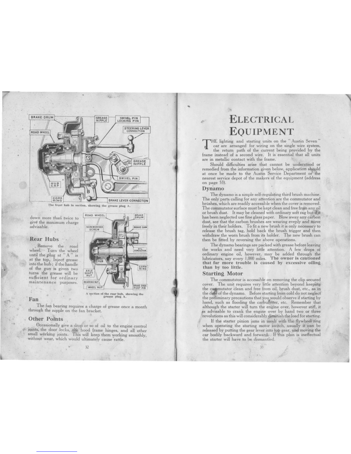
The front brake cam
spindJe, is lubricated from
the swivel pin as shown
at (B), in the illustration
overleaf.
30
,"
.
~
Front Axle'
The swivel pins are lubricated with the grease gun and
should receive attention once a week.
Radius Rod Anchora~e
Oil should be applied occasionally to the cups and ball
flange, forming the radius rod anchorage on ihe front cross
member, just below the rear of the gearbox.
Shock Absorbers
The shock absorbers should be lubricated only after
dismantling them (see page 47). '
Windscreen Wiper
A drop of thin oil should be occasionally applied to the
windscreeri wiper mechanism-say, once a month. A small
screw (except in the Trico model) is removable from the top of
the casing allowing the oil to be injected.
"
Road Sprin~s
The ends of the road springs where they are attached to the
axles are provided with grease gun connections, and should be
given a charge once a week if the car is continually used. After
a long period of use it is advisable to lubricate the leaves of the
spring with a warm mixture, of white lead and tallow in equal
parts. This can best be applied with a stiff brush, the leaves
being eased apart by a screwdriver; first jack up the car,
not under the axles, nor the radius rods, but under the frame to
take the weight off the springs, The rear 01 the car can be
jacked up one side at a time. The best point of the frame a~
which to apply the jack is each end of the rear cross-member.
At the front, as there is only one transverse spring, the whole
01the car must be lilted, and as a safety measure, the rear wheels
should be " scotched" to prevent the car running off the jack.
A short stiff bar is placed across the frame, just lorward 01 the
engine. oil reservoir, and behind the spring, and the jack lilts
the car Irom the centre 01 this bar. It will be necessary to block
the jack up for this work, with a wood block, to avoid
necessitating an excessive lilt.
1
Front Hubs
Remove the road wheel (see page 11). Turn the hub until
the plug" A" is at the top. Screw out the plug and screw
in the adapter ,which is provided in the kit.
Fill the hub with grease. It is important that the hubs are
not given too much Rrease, otherwise the brakes will not be
effective. The handle 01 the grease-gun should not be turned
I
31
j
[-
I
.~
.
......
,.
down more thari twice to
give' the maximum charge
advisable.
Rear Hubs' .'
Remove the road
wheel. Turn the wheel
until the plug at .. A" is
at the top. Injeci grease
into the hub; if the handle
of the gun is givcn two
turns the grease will be
sufficient for ordinary
ma'intenance purposes.
'.
GREASE
NIPPLE SWIVEL, PI N
LOCKING PIN
WHEELNUT """"OE
POVOT.,.
A ",ct/on of the ce.. hub, .howlng the
,g".., plu~A.
Fan "
The fan bearing requires a charge of grease once a month
through the nipple on the fan bracket.
"
Other Points
Occasionally give a drop or so of oil to the engine control
joints, the door locks, (110hood frame hinges, and all other
small working joints. This will keep them working smoothly.
without wear, which would ultimately cause "rattle.
v
-32 --
-
-.'
-- ----"'
,,,>
... ELECTRICAL
EQUIPMENT
THE lighting and starting units on the" Austin Seven ..
I car are arranged for wiring on the single wire system,
the return path of the current being provided by the
frame instead of a second wire. It is essential that all units
are in metallic contact with the frame.
Should difficulties arise that cannot be understood or
remedied from the information given below, application sh,o~ld
at once be made to the Austin Service Department or the
nearest service depot of the makers of the equipment (address
on page 53).
Dynamo '
The dynamo is a simple self.regulating third brush machine.
The only parts calling for any attention are the commutator and
brushes, which are readily accessible when the cover is removed.
The commutator surface must be kept clean and free frOp. any oil
or brush dust. It may be cleaned with ordinary soft rag buti~it
has been neglected use fine glass paper. Blow away any carbon
dust, see that the carbon brushes are wearing evel'ly and move
freely in their holders. To fit a new brush it is only necessary to
release the brush tag, hold back the brush trigger and then
withdraw the worn brush from its holder. The new brush can
then be fitted by reversing the above operations.
The dynamo bearings are packed with grease before leaving
the works and need very little attention. A few drops of
ordinary engine oil, however, may be added through the
lubricators, say every 1.000miles. The owner is cautioned
that far more trouble is caused by excessive oiling
than by too little.
Starting Motor
The commutator is accessible on removing the clip secured
cover. The unit requires very little attention beyond keeping
the s<>W"'utatorclean and free from oil, brush dust, etc., as in
the ~of the dynamo. Before starting from cold do not neglect
the pri!Iiminary precautions that you would observe if starting by
'L.
hanq, such as flooding the carburetter, etc. Remember that
although the starter will turn the engine over, however stiff, it
;.s advisable to crank the engine over by hand two or three
"revolutions as this will considerably diminish the load for starting.
If the starter pinion jams in 4esh with the flywheehing
when operating the starting motor switch, usually it can be
released by putting the gear lever into top gear, and moving the
car bodily backward and forwank IMhis plan is ineffectual
the starter will have to be dismantled. ;.
I
33
,
-
,'\
Never use the starting motor to propel the car, as it throws
too severe a strain on the battery and the starting motor.
If the engine does not start at the first attempt. do not press
the starter switch until the engine has come to rest. If this
precaution is not adopted, the starter ring teeth on the flywheel
cover, or the starter pinion teeth, may be damaged.
If the maximum ammeter reading is much below normal
when the dynamo is charging when the lamps are" off "; or if
the needle fluctuates when the car is running steadily, a low or
intermittent dynamo output can be suspected. The dynamo
may have been neglected, and the trouble may be caused by
say worn brushes, or a dirty commutator (refer to the dynamo
recommendations).
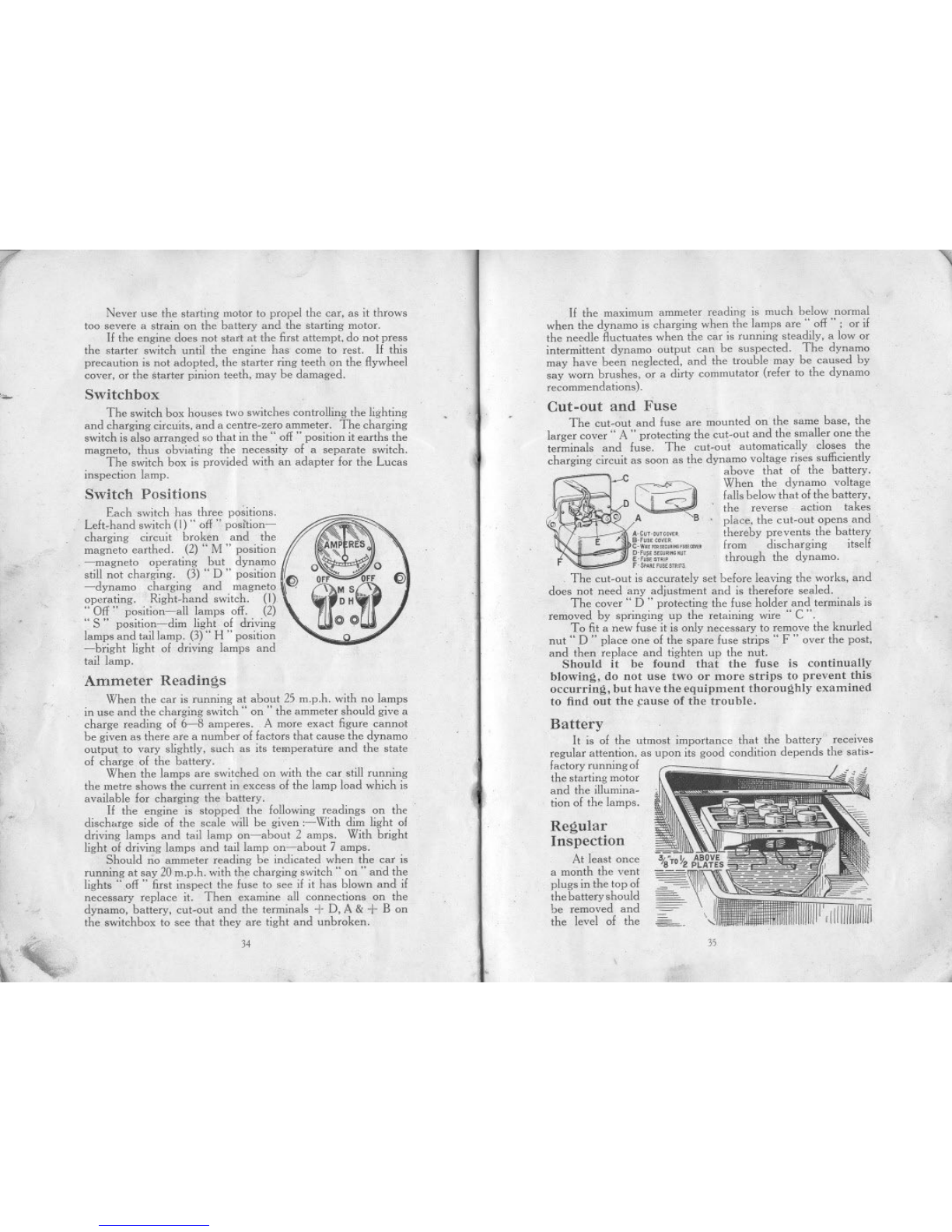
Cut-out and Fuse
The cut-out and fuse are mounted on the same base, the
larger cover" A " protecting the cut-out and the smaller one the
terminals and fuse. The cut-out automatically closes the
charging circuit as soon as the dynamo voltage rises sufficiently
c above that of the battery.
.~. When the dynamo voltage
D~falls below that of the battery,
. . the reverse action takes
010» ,A B .place, the cut-out opens and
A-C"',,~,,~, thereby prevents the battery
B-"""'" f d.h..If
c-w,""o"""",",ru..~,, rom lSC argmg ltse
D'""',""","'~ h h h d
E-"""'" t roug t e ynamo.
"""'"""",,.
. The cut-out is accurately set before leaving the works, and
does not need any adjustment and is therefore sealed.
The cover" D " protecting the fuse holder and terminals is
removed by springing up the retaining wire" C ".
To fit a new fuse it is only necessary to remove the knurled
nut" D " place one of the spare fuse strips" F " over the post,
and then replace and tighten up the nut.
Should it be found that the fuse is continually
blowing, do not use two or more strips to prevent this
occurring, but have the equipment thoroughly examined
to find out the .cause of the trouble.
Battery
It is of the utmost importance that the battery receives
regular attention, as upon its good condition depends the satis-
factory running of
the starting motor
and the illumina-
tion of the lamps.
""- Switchbox
The switch box houses two switches controlling the lighting
and charging circuits, and a centre-zero ammeter. The charging
switch is also arranged so that in the" off " position it earths the
magneto, thus obviating the necessity of a separate switch.
The switch box is provided with an adapter for the Lucas
inspection lamp.
Switch Positions
Each switch has three positions.
Left,hand switch (I)" off" position-
charging circuit broken and the
magneto earthed. (2)" M " position
-magneto operating but dynamo
still not charging. (3)" D " position !~~
-dynamo charging and magneto \\ .
operating. Right-hand switch. (I)
" Off " position-all lamps off. (2)
" S" position-dim light of driving
lamps and tail lamp. (3)" H" position
-bright light of driving lamps and
tail lamp.
F
~.
Ammeter Readings
When the car is running at about 25 m.p.h. with no lamps
in use and the charging switch" on " the ammeter should give a
charge reading of 6-8 amperes. A more exact figure cannot
be given as there are a number of factors that cause the dynamo
output to vary slightly, such as its temperattire and the state
of charge of the battery.
When the lamps are switched on with the car still running
the metre shows the current in excess of the lamp load which is
available for charging the battery.
If the engine is stopped the following readings on the
discharge side of the scale will be given :-With dim light of
driving lamps and tail lamp on-about 2 amps. With bright
light of driving lamps and tail lamp on-about 7 amps.
Should rio ammeter reading be indicated when the car is
running at say 20 m.p.h. with the charging switch" on " and the
lights ".off " first inspect the fuse to see if it has blown and if
necessary replace it. Then examine all connections on the
dynamo, battery, cut-out and the terminals -I- D, A & -I- B on
the switchbox to see that they are tight and unbroken.
Regular
Inspection
At least once
a month the vent
plugs in the top of
the battery should
be removed and
the level of the
..
~.,
34
--
35
Other manuals for Austin Seven
1
Table of contents
Other Austin Motor Company Automobile manuals

Austin Motor Company
Austin Motor Company A40 Somerset Sedan User guide

Austin Motor Company
Austin Motor Company LANDCRAB 1993 User manual

Austin Motor Company
Austin Motor Company Austin Seven User manual

Austin Motor Company
Austin Motor Company A40 Somerset Sedan Technical specifications

Austin Motor Company
Austin Motor Company FX4R User manual


