Austin Motor Company A40 Somerset Sedan Technical specifications

NUSTIIU
A4O }IODELS
Ruiltll{G AllD
ITAITTETAlÜCE
lnsTR,ucrlons

/\
ú-**
A40
MODELS
RUNN I NG AND
MAI NTENANCE
INSTRUCTIONS
JANUARY t953
THE AUSTI N MOTOR CO. LTD.
LONGBRTDGE, BTRMTNGHAM
BOX 4r c.P.O.
NUSTIN
PUBLICATION No. 881/E
WORLD COPYRIGHT
PRINTED IN ENGLAND
THE AUSTIN'A4O' MAINTENANCE INSTRUCTIONS
INTRODUCTION
THIS booklet gives the running instructions necessary
r to ensure satisfactory operation of the '440' Somerset
Saloon, Coupé, Sports Model, Countryman, Pick-up and
Delivery Van.
It does not include major maintenance attentions,
which should be entrusted to the local Austin dealer, who
will use only genuine Austin parts as replacements.'
A Supplement has been included covering all those
items on the 'A40' Sports Model which are not common
to the Saloon,
The owner should bear in mind that the warranty does
not cover any failure due to inadequate maintenance, nor
is it extended or varied in any way by the following recom-
mendations.
Accessories and equipment are subject to the warranties
issued by their makers, a list of whom appears at the end
of this booklet.
Alterations in design may sometimes occur which
entails additional or varied maintenance work. It is not
always immediately possible to include such details in the
handbook, therefore operators are advised to keep in touch
with their local Austin dealer's service department.
t

\
z
o
o
Fl
o
Fr
Í!
a
ú
t!
o
o
z
F
a
D
a
F
-1
\p
p"
D
o
O
í
z
F
a
)
Fì
F

\
z
ú
E
ì
a
H
1
3
z
F
a
trÌ
F
-1
z
ú
F
z
o
o
;
F
a
Fì
F

\
È
D
v
o
I
2
F.
h
D
Íq
t-
-1
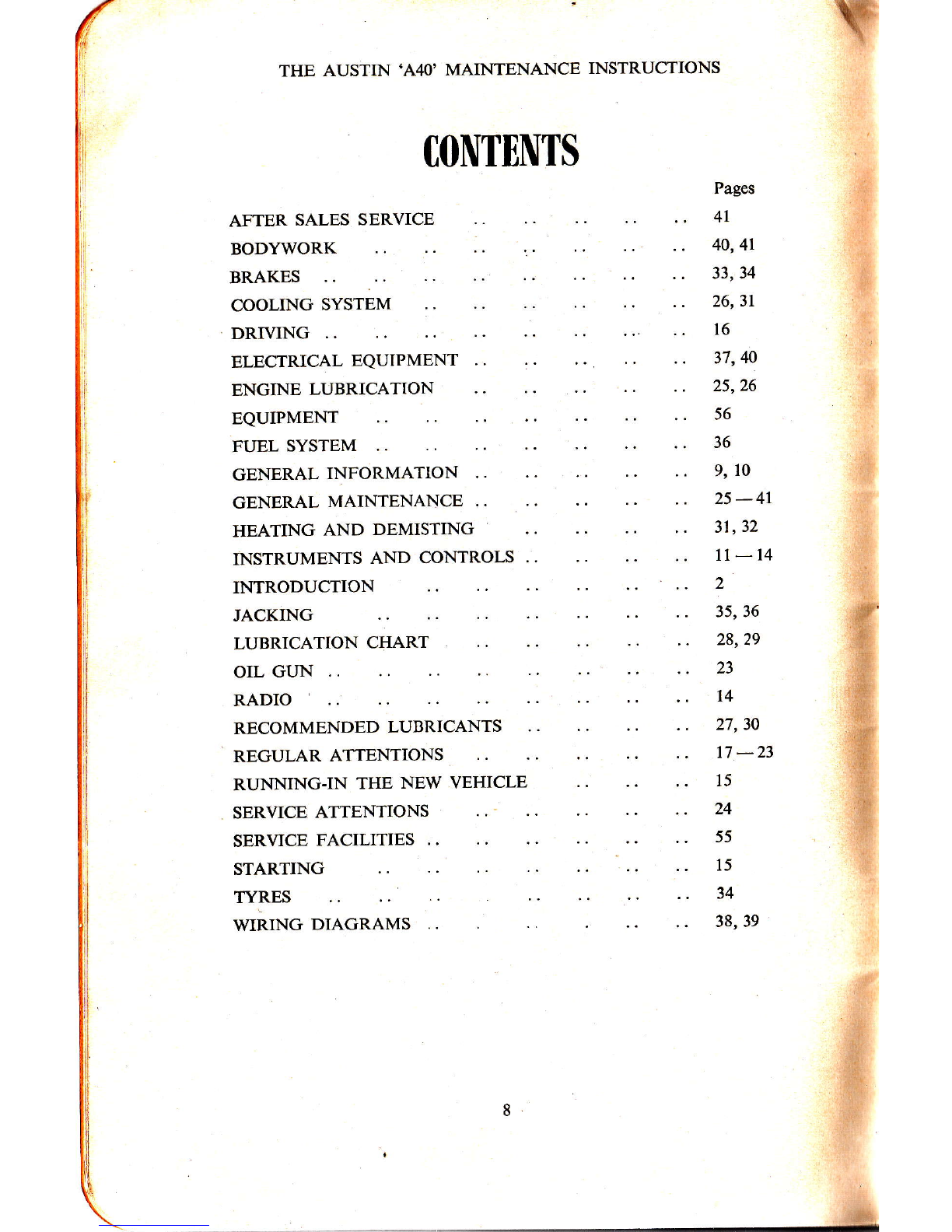
CONTENTS
AFTER SALES
BODYWORK SERVICE
BRAKES
COOLING SYSTEM
DRIVING
ELECTRICAL EQUIPMENT
ENGINE LUBRICATION
EQUIPMENT
FUEL SYSTEM
GENERAL INFORMATION
GENERAL MAINTENANCE ..
HEATING AND DEMISTING
INSTRUMENTS AND CONTROLS ..
INTRODUCTION
JACKING
LUBRICATION CHART
OIL GUN
RADIO
RECOMMENDED LUBRICANTS
REGULAR ATTENTIONS
RUNNING-IN THE NEW
SERVICE ATTENTIONS
VEHICLE
THE AUSTIN .A4O' MAINTENANCE INSTRUCTIONS
TYRES
Pages
4l
40,41
33,34
26,31
16
37,40
25,26
56
36
9, 10
25-4r
31,32
1l-14
2
35, 36
28,29
23
l4
27,30
17 -23
15
24
55
15
34
38, 39
#'
s
-tìj
il
.ìt
d
.{.
'JÌ:
r#
tffi
-l:
1{
.{::
p
I
SERVICE FACILITIES
STARTING
WIRING DIAGRAMS
.,#
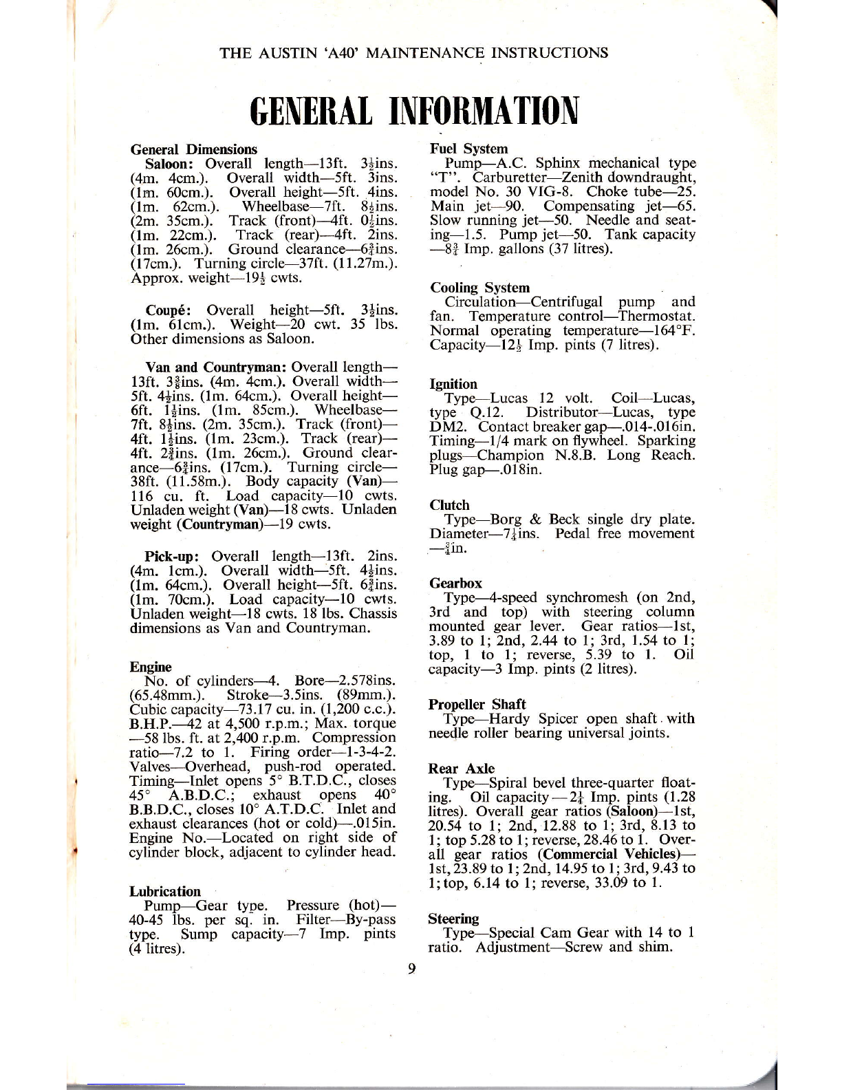
TENHRAT INF()RMATION
General Dimensions
Saloon: Overall length-l3ft. 3+ins.
(4m. 4cm.). Overall width-5ft. 3ins.
(1m. 60cm.). Overall height-5ft. .4ins.
(1m. 62cm.). Wheelbase-7fl. 8|ins.
(2m. 35cm.). Track (front)--4ft. 0+ins.
(lm. 22cm.). Track (rear)-4ft. 2ins.
(lm. 26cm.). Ground clearance-6fins.
(17cm.). Turning circle-37ft. (11.27m.).
Approx. weight-l9à cwts.
Coupé: Overall height-5ft. 3âins.
(1m. 61cm.). Weieht-20 cwt. 35 lbs.
Other dimensions as Saloon.
Van and Countryman: Overall length-
13ft. 3$ins. (4m. 4cm.). Overall width-
5ft. 4*ins" (lm. 64cm.). Overall height-
6ft. 1$ins. (1m. 85cm.). Wheelbase-
7ft. 8Èins. (2m. 35cm.). Track (front)-
4ft. làins. (1m. 23cm.). Track (rear)-
4ft. 2fins. (lm. 26cm.). Ground clear-
ance-6lins. (l7cm.). Turning circle-
381t. (11.58m.). Body capacity (Van.)-
11ó cu. ft. Load capacity-lo cwts.
Unladen weight (Van)-18 cwts. Unladen
weight (Countryman)-19 cwts.
Pick-up: Overall length-l3ft. 2ins.
(4m. lcm.). Overall $'idth-sft. 4+ins.
(1m. 64cm.). Overall height-Sft. 6Êins.
(lm, 70cm.). Load capacity-l0 cwts.
Unladen weieht-l8 cwts. 18 lbs. Chassis
dimensions as Van and Countryman.
Engine
No. of cylinders-{. Bore-2.578ins.
(65.48mm.). Stroke-3.5ins. (89mm.).
Cubic capacity-l3.17 cn. in. (1,200 c.c.).
B.HP.-42 at 4,500 r.p.m.; Max. torque
-58 lbs. ft. at2,4Oo r.p.m. Compression
rati:o-l.2 to l, Firing order-l-3-4-2.
Valves-Overhead, push-rod operated.
Timing-Inlet opens 5' B.T.D.C., closes
45" A.B.D.C.; exhaust opens 40"
B.B.D.C., closes l0'A.T.D.C. Inlet and
exhaust clearances (hot or cold)-.Ol5in.
Engine No.-Located on right side of
cylinder block, adjacent to cylinder head.
Lubrication
Pump-Gear type. Pressute (hot)-
40-45 lbs. per sq. in. Filter-By-pass
type. Sump capacity-7 Imp. pints
(4 litres).
\
THE AUSTIN'A4O' MAINTENANCE INSTRUCTIONS
Fuel System
Pump-A.C. Sphinx mechanical type
"T". Carburetter-Jenïth downdraught,
model No. 30 VIG-8. Choke tube-25.
Main jet-90. Compensating jet-65.
Slow running jet-50. Needle and seat-
ing-1.5. Pr.rmp jet-50. Tank capacity
-8f Imp. gallons (37 litres).
Cooling System
Circúation-Centrifugal pump and
fan. Temperature control-Thermostat.
Normal operating temperature-164'F.
Capacity-l2t Imp. pints (7 litres).
Ignition
Type-Lucas 12 volt. Coil-Lucas,
type Q.12. Distributor-Lucas, type
DM2. Contact breaker gap-.014-.016in.
Timing-l/4 mark on flywheel. Sparking
plugs-Champion N.8.8. Long Reach.
Plug gap-.018in.
Clutch
Type-Borg & Beck single dry plate.
Diameter-7]ins. Pedal free movement
J*in.
Gearbox
Type--4-speed synchromesh (on 2nd,
3rd and top) with steering column
mounted gear lever. Gear ratios-lst,
3.89 to l; 2nd,2.44 to 1; 3rd, 1.54 to l;
top, 1 to l; reverse, 5.39 to 1. Oil
capacity-3 Imp. pints (2 litres).
Propeller Shaft
Typo-Hardy Spicer open shaft. with
needle roller bearing universal joints.
Rear Axle
Type-Spiral bevel three-quarter float-
ing. Oil capacity-2! lmp. pints (1.28
litres). Overall gear ratios (Saloon)-1st,
20.54 to l;2ttd,12.88 to l;3rd,8.13 to
1; top 5.28 to 1; reverse, 28.46 to 1. Over-
all gear ratios (Commercial Vehicles)-
1 st, 23.89 to 7 ; 2nd, 14.95 to I ; 3rd, 9.43 to
l.;top,6.14 to 1; reverse, 33.09 to 1.
Steering
Type-Special Cam Gear with 14 to I
ratio. Adjustment-Screw and shim.
THE AUSTIN'A4O' MAINTENANCE INSTRUCTIONS
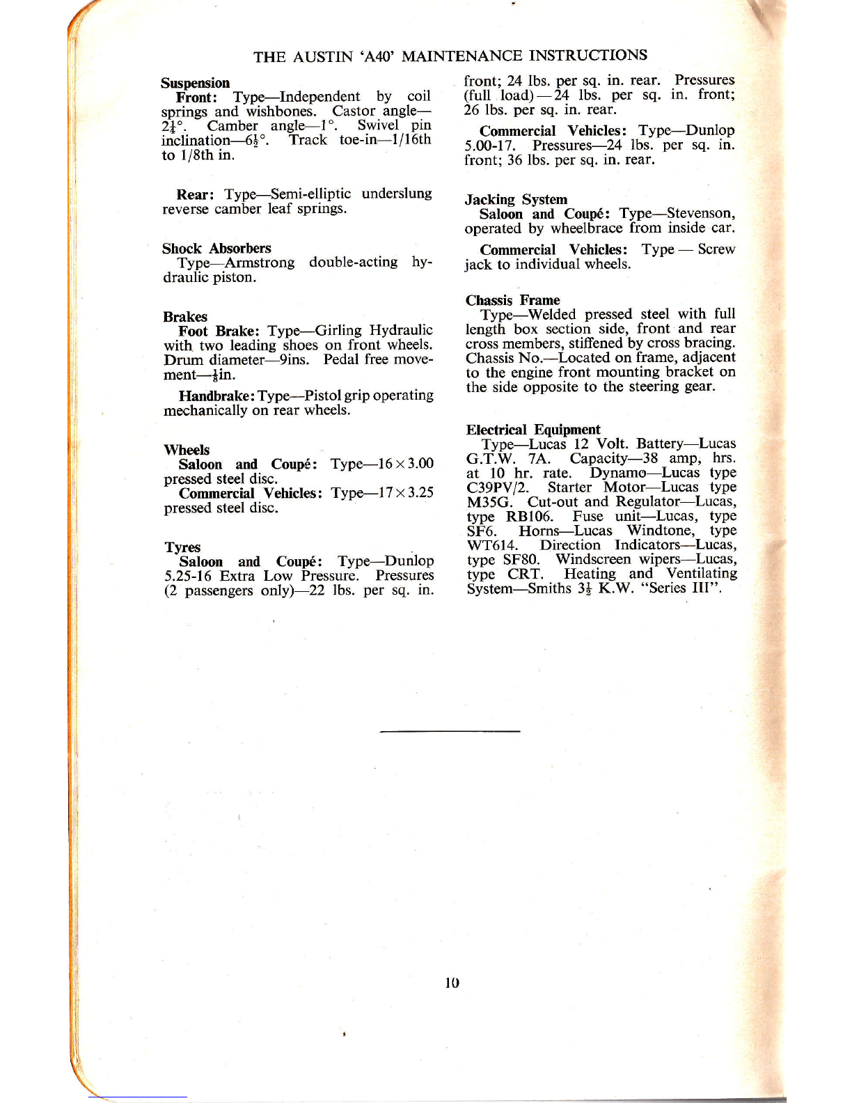
Suspension
Flont: Type-ìndependent by coil
springs and wishbones. Castor angle-
tf". Camber angle-l '. Swivel pin
inclination-6É". Track toe-in-l/l6th
to l/8th in.
Rear: Type-Semi-elliptic underslung
reverse camber leaf springs.
Shock Absorbers
Type-Armstrong double-acting hy-
draulic piston.
Brakes
Foot Brake: Type-Girling Hydraulic
with two leading shoes on front wheels.
Drum diameter-9ins. Pedal free move-
ment-{in.
Handbrake : Type-Pistol grip operating
mechanically on rear wheels.
Whecls
Saloon anrl Coupé: Type-I6 x 3.00
pressed steel disc.
Commercial Vehicles: Type-l7 x 3.25
pressed steel disc.
Tyres
Saloon and Coupé: Type-Dunlop
5.25-16 Extra Low Pressure. Pressures
(2 passengers only)-22 lbs. per sq. in.
front;'24 lbs. per sq. in. rear. Pressures
(full load)-24 lbs. per sq. in. front;
26 lbs. per sq. in. rear.
Commercial Vehicles: Type-DunloP
5.00-17. Pressures-24 lbs. per sq. in.
front; 36 lbs. per sq. in. rear.
Jacking System
Saloon and Coupé: Type-Stevenson,
operated by wheelbrace from inside car.
Commercial Vehicles: Type - Screw
jack to individual wheels.
Chassis Frame
Type-Welded pressed steel with full
length box section side, front and rear
crois members, stiffened by cross bracing.
Chassis No.-Located on frame, adjacent
to the engine front mounting bracket on
the side opposite to the steering gear.
Electrical Equipment
Type-Lucas 12 Volt. Battery-Lucas
G.T.W. 74. Capacity-38 amp, hrs.
at 10 hr. rate. Dynamo-Lucas type
C39PVI2. Starter Motor-Lucas type
M35G. Cut-out and Regulator-Lucas,
type RB106. Fuse unit-Lucas, type
SF6. Horns-Lucas Windtone, type
WT6l4. Direction Indicators-Lucas,
type SF80. Windscreen wipers-Lucas,
type CRT. Heating and Ventilating
System-Smiths 3à K.W. "Series III".

.I
THE AUSTIN'A4O' MAINTENANCE INSTRUCTIONS
INSTRUilIENTS AND CONTROTS
MNOPQRST
I
THE SALOON AND COUPE INSTRUMENT PANEL
H40. 23Ì. Â
A-Fuel gauge.
B-Ammeter.
C-Eeadlight beam warning light.
D-Speedometer.
E-Ignition varning light.
F-0il pressure gauge.
G -úl/at er t eu pe rat ure gauge.
H-Choke control, P-Speedometet ftip contrcl.
I-lvindscreen wiper control. Q-Panel light swítch.
K-Extra air control. R-Statter control.
L-Áir control. S-Radio onlof switch.
M -Denústerldefroster control. T-Tone contrcl.
N-Ignition qnd lighting sútch. U-Tuning push-bultons.
O-Heater ruotor swilch. V-Manual luning contol.
E-Oil pressure warning lìght. I-Headlight watnìng light'
F -Fuel gauge. J- Thcürcmeler.
G -Mileage recorder. K- Panel light switch.
H-Ìsnitiòn warnìng light, L-Starter contol.
Á-Choke control.
B-Windscreen wipet swìtch.
C-Ignition and lighting swiíc|1.
D-Speedometer.
THÊ COMMERCIAL VEHICLE INSTRUMENT PANEL
INSTRTIMNNTS
Speedometer: Registers the vehicle
speed and total mileagb. The trip figures
at the top of the speedometer can be set
to zero by pushing in the springJoaded
knob on the right-hand side of the heater
control panel, and turning it in an anti-
clockwise direction.
Oil Pressure Gauge (Saloon and
Coupé): Indicates the oil pressure in the
engine. It does not slÌow the quantity of
oil in the sump.
Oil Pressure Warning Light (Commer-
cial Vehicles): Glows red when the
ignition is switched on and fades out
after the engine has been started. Low
oil pressure or insumcient oil in the sump
THE AUSTIN'A4O' MAINTENANCE INSTRUCTIONS
is indicated by ared glow whentheenginc
13 ruÌnmg,
Ammeter (Saloon and Coupé): Indicates
the flow of current into or out of the
battery. With the automatic voltage
control system little or no charge is shown
when the battery is well charged.
Igrition Warning Light: Glows red
when the ignition is switched "on" and
fades out when the dynamo is charging
the baltery.
Headlight Beam Warning Light: A red
glow appears when the full headlights are
switched on, with the two beams full
ahead. The light goes out when the head-
lights are dipped.
Fuel Gauge: Indicates the contents of
the tank when the ignition switch is on.
When the tank is being filled, switch off
and stop the engine. Switch on again and
the needle will record the amount of fuel
entering the tank.
Water Temperature Gauge (optional
extra on Commercial Vehicles): This
records the temperature of the cooling
water circulating in the cylinder block and
radiator. The correct operating tempera-
ture under normal conditions should not
be below 164'F.
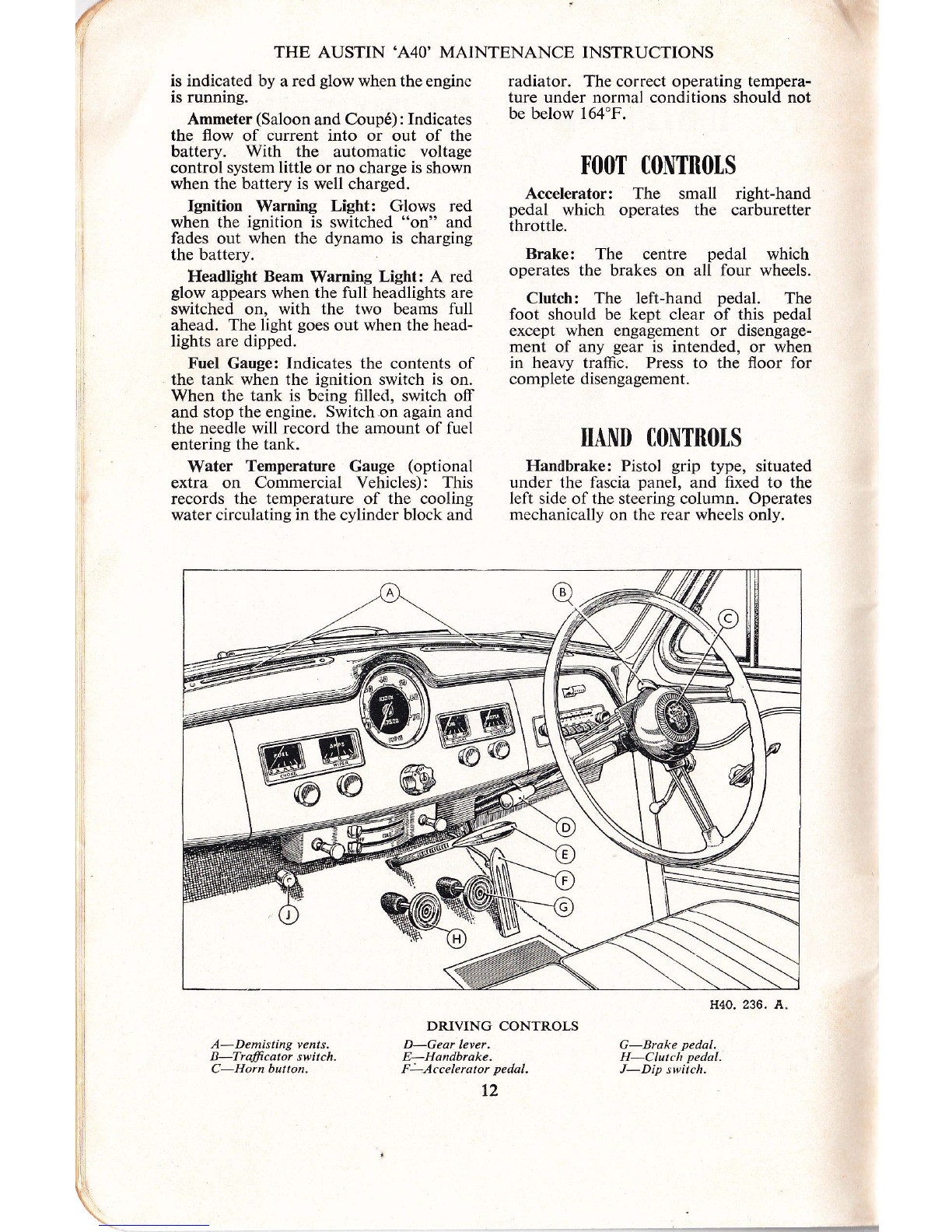
F()()T CONTNOTS
Accelerator: The small right-hand
pedal which operates the carburetter
throttle.
Brake: The centre pedal which
operates the brakes on all four wheels.
Clutch: The left-hand pedal. The
foot should be kept clear of this pedal
except when engagement or disengage-
ment of any gear is intended, or when
in heavy traffic. Press to the floor for
complete disengagement.
HAND CONTIÌOIS
Handbrake: Pistol grip type, situated
under the fascia panel, and fixed to the
lelt side of the steering column. Operates
mechanically on the rear wheels only.
H40. 236. A
G-Brake pedal.
H-Clutch pedal.
J-Dip switch.
A-Demisting vents.
B-Trafrcatot switch.
C-Hotn button,
DRIVING CONTROLS
D-Geqr leyer.
E-Handbrake.
F-Accelerator pedal.
t2
ffi Wffi
@-é

THE AUSTIN'A4O' MAINTENANCE INSTRUCTIONS
Gear Lever: Should alwavs be in
neutral when starting the enline. The
lever is mounted on the left side of the
steering column. To engage a gear,
depress the clutch and move the lever to
the required position as described on
page 16.
Choke Control: Pull the control out to
its limit when starting the engine lrom
cold. Once the engine is running, push
in the choke control completely as ioon
as the engine will run evenly without its
use.
Ignition Switch: Turn the key clockwise
to s\üitch on. Do not leave the switch
"on" when the vehicle is stationary-the
red warning lamp is a reminder. The
ignition key may also be used for locking
the driver's door and the luggage or load
compartment.
Lighting Switch: This is the moulding
which surrounds the ignition switch.
Turn clockwise to the first notch to put
on the sidelights, and to the second to
put on the headlights. The headlights are
dipped by foot operation.
Starter Switch Knob: Pull out the
control knob to start, and release as soon
as the engine fires. If the engine fails to
start after a few revolutions, do not
operate the starter again until the engine
rs statlonary,
Direction fndicators: The indicators are
controlled from the centre of the steering
wheel. Normally, after the vehicle has
turned a corner, they return automatically,
but when only a slight turn has been made
it may be necessary to return them
manually with the switch.
Heater and Demister Controls (Saloon
and Coupé): These are situated centrally
below the fascia and provide the means for
regulating the heating and demisting
system. Full operating instructions are
given on page 31.
Extra Air Control (Saloon and Coupé):
A supply ofcold air, entirely independent
of the heating system, can be admitted to
the car interior for ventilation purposes
by pulling out the control located on the
Ieft-hand side of the heater panel.
Heater Control Switch (Commercial
Vehicles): Turn to the right until a click
is heard. This starts the heater fan. The
further the control is turned the less will
be the speed of the fan, due to the fact
that a rheostat is incorporated.
Windscreen Wipers: To start the eiectric
wipers pull out the wipers control. To
park, switch off by pressing the control
inwards when the arms are at the end of
the stroke. Do not try to push the arms
across the windscreen by hand.
In the case of the Commercial Vehicles
the wipers are controlled by a rotary
switch situated at the top leflt-hand side
ofl the instrument panel.
Panel Light Switch: Pull out the switch
control knob to illuminate the instru-
ments. Only operates when the side-lamps
are "on."
In the case of the Commercial Vehicles
the panel lights are controlled by a rotary
switch situated at the top right-hand side
of the instrument panel.
Horn Button: Mounted at the centre of
the steering wheel, and cah be operated
independently of the ignition switch.
Interior Light: Combined with a switch
in the roof.
Spare Wheel: Secured at the rear of the
Saloon in the luggage compartment, and
under the load platform of the Commer-
cial Vehicles.
Seating: Adjustable front seats or bench
type seat in Saloon and Coupé, single ad-
justable seat in Delivery Van and full width
bench type seat in Pick-up. The Country-
man driver's seat may be adjusted and the
front passenger seat squab and cushion
both hinge forward to give access to rear
seating.
Doors: The right side front door, the
luggage compartment of the Saloon and
Coupé and the rear doors ofthe Country-
man and Delivery van may be locked
with the ignition key. The other doors
may be locked by lifting the inside door
handles.
An additional safety lock is fitted to
the rear door interior locking handles of
the Saloon. This device is intended to
prevent inadvertent opening ofthe doors,
particularly by children, when the vehicle
is in motion.
To lock the doors, turn the escutcheon
in a clockwise direction on the left door
handle and anti-clockwise on the right
door handle. This can only be effected,
however, when the handles are in the
unlocked position.
4
13
THE AUSTIN'A4O' MAINTENANCE INSTRUCTIONS
H?0 119 À
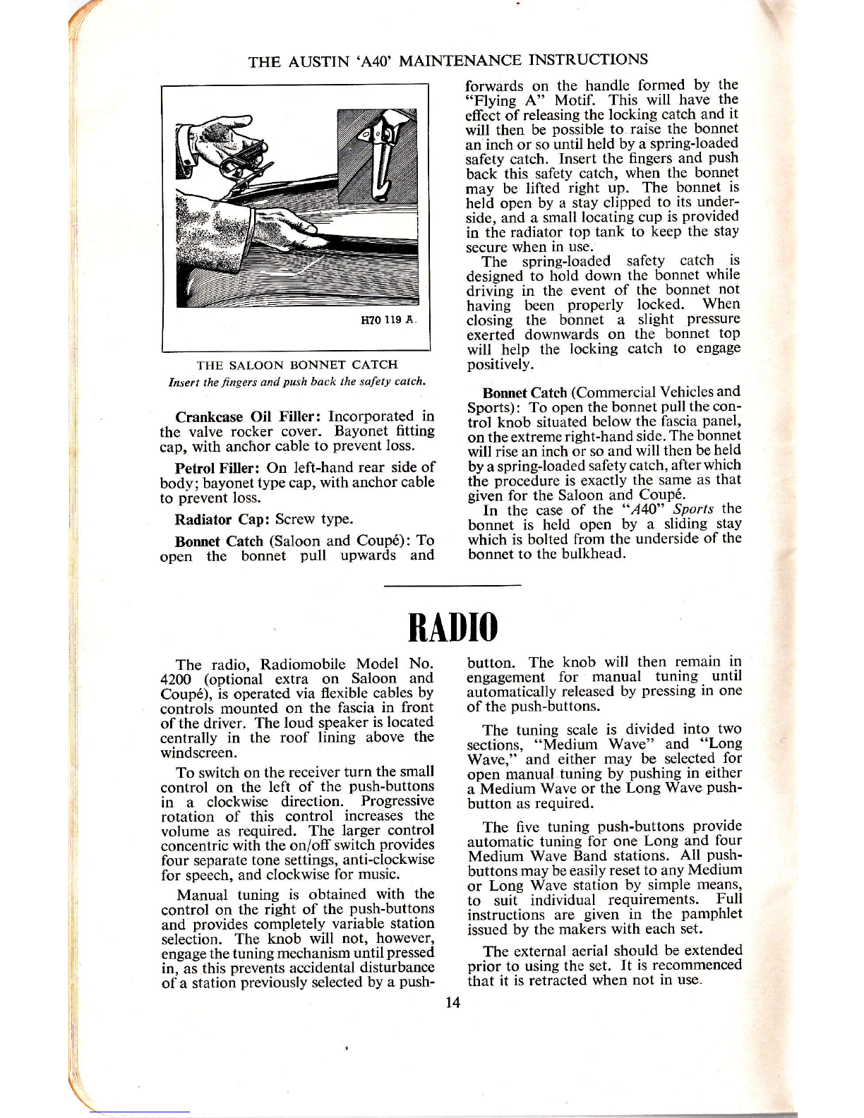
THE SALOON BONNET CATCH
Insert the rtngers and push back the safety cutch'
Crankcase Oil Filler: Incorporated in
the valve rocker cover. Bayonet fitting
cap, with anchor cable to prevent loss.
Petrol Filler: On left-hand rear side of
body; bayonet type cap, with anchor cable
to prevent loss.
Radiator Cap: Screw type.
Bonnet Catch (Saloon and CouPé): To
open the bonnet pull uPwards and
forwards on the handle formed by the
"Flvine A" MotiL This will have the
effeót oÍ releasing the locking catch and it
will then be possible to raise the bonnet
an inch or so until held by a springJoaded
safety catch. lnserl the fingers and push
back this safety catch, when the bonnet
may be lifted right up. The bonnet is
held open by a stay clipped to its under-
side, ahd a small locating cup is provided
in the radiator top tank to keep the stay
secure when in use.
The spring-loaded saletY catch is
designed ìo trãlO down lhe 6onnet while
driving in the event of the bonnet not
having been properly locked. When
closing the bonnet a slight pressure
exerted downwards on the bonnet top
will help the locking catch to engage
positively.
Bonnet Catch (Commercial Vehicles and
Sports): To open the bonnet pull the con-
trol knob situáted below the fascia panel,
on the extreme right-hand side. The bonnet
will rise an inch or so and will then be held
by a spring-loaded salety catch. afterwhich
the piocedure is exactly the same as that
given for the Saloon and CouPé.
- In Íhe case of ttre "A40" SPorts the
bonnet is held open by a sliding stay
which is bolted lrom the underside of the
bonnet to the bulkhead.
li
I
lrl
(
RÀDIO
The radio, Radiomobile Model No.
4200 (optional extra on Saloon and
Coupé), is operated via flexible cables by
controls mounted on the fascia in front
ofthe driver. The loud speaker is located
centrally in the roof lining above the
windscreen.
To switch on the receiver turn the small
control on the left of the push-buttons
in a clockwise direction. Progressive
rotation of this control increases the
volume as required. The larger control
concentric with the on/off switch provides
four separate tone settings, anti-clockwise
for speech, and clockwise for music.
Manual tuning is obtained with the
control on the right of the push-buttons
and provides completely variable station
selection. The knob will not, however,
engage the tuning mechanism until pressed
in, as this prevents accidental disturbance
of a station previously selected by a push-
button. The knob will then remain in
engagement for manual tuning until
auiomatically released by pressing in one
of the push-buttons.
The tuning scale is divided into two
sections, "Medium Wave" and "Long
Wave," and either may be selected for
open manual tuning by pushing in either
a Medium Wave or the Long Wave Push-
button as required.
The five tuning push-buttons provide
automatic tuning for one Long and four
Medium Wave Band stations. All push-
buttons may be easily reset to any Medium
or Long Wave station by simple means,
to suii individual requirements. Full
instructions are given in the pamphlet
issued by the makers with each set.
The external aerial should be extended
prior to using the set. It is recommenced
ihat it is retracted when not in use.
t4
THE AUSTIN'A4O' MAINTENANCE INSTRUCTIONS
STARTING
PEFOR_E starting the engine check the oil level in the sump and the water level in
r-lthe radiator. Ensure that the gear lever is in neutral and that the hand-brake is
a-pplie{, If the engine is cold pull out the choke control. In cold weather the engine
should be rotated several times with the starting handle. Do not ptrmp the accelera-tor.
radiator will assist the engine to warm
up quickly, but always uncover the
radiator before driving off. Push in the
choke control completely as soon as the
engine will run evenly without its use.
When the vehicle has been out of use
for several days the fuel in the carburetter
may have evaporated. Before attempting
to start the engine refill the carburetter
by operating the priming lever on the
fuel pump, which is located low down on
the left side of the engine.
The pumping action should be dis-
tinctly felt until the carburetter bowl is
full. If this pumping action cannot be
felt, turn the engine with the starting
handle about onefull turn, whereupon the
priming lever should be free to pump.
Switch on the ignition; ensure that the
ignition warning light glows and that the
fuel gauge registers; then pull the starter
control firmly. Release it il the engine
fails to start within five or six seconds,
wait for the engine to stop rotating and
then pull the starter again.
Should the engine not start after a
reasonable number of attempts, check up
on possible causes. Do not persist in
operating the starter, as a great strain is
inposed on the battery by so doing. As
soon as the engine starts, release the
starter and warm the engine up at a
fairly fast idling speed.
Do not, under any circumstances, race
the engine in an attempt to warm up the
engine more quickly. Blanking off the
The following speeds should not be
exceeded in the gears Íor the first 500
miles.
1st
m.p.h.
6-7
It is most important to remember that
at no time during the running-in period
must the engine be over-loaded, as in
attempting to ascend hills in top gear at
low vehicle speed. The load should be
eased by changing down to a lower gear.
Fierce acceleration must also be
avoided, and remember that the engine
should never be raced in neutral.
2nd 3rd Top
m.p.h. m.p.h. m.p.h.
1t-12 17-18 30
RUNNINÊ"IN THE NEW VHHICTE
f4E Austin 'A40,' is designed and built with great care to high quality standards.
I For that reason the owner will find that consideúte treatment du-ring the áIl-important
running-in period will be well repaid by trouble free running and mãximum efiìciency
throughout its life. On completion of the first 500 miles
the running-in speed in each gear may be
progressively increased, but full power
should not be used until at least 1,500
miles have been covered. and even then
only for short periods at'a time. During
this mileage a slight falling-off in engine
power may develop, in which case it is
beneficial to lightly grind-in the valves
and re-set the valve clearances. No
engine or complete vehicle can be con-
sidered fully run-in until it achieves
2-3,000 miles.
The use of upper cylinder lubricant is
recommended at all times, but most
particularly during the running-in period.
See centre pages for recommended
brands.
4
15

THE AUSTIN'A4O' MAÌNTENANCE INSTRUCTIONS
I}RIYING
t-ÍtHE eearbox has four forward speeds and a reverse. Start only in first gear, which
I is enÉaged by depressing the cldtch pedal and moving the gear lever away from the
steering*wáeel ánd ïhen upwards. Shóuld the gear not readily engage, momentarily
releasithe clutch pedal; âfter which, with the clutch again depressed, it should be
possible to engage úe gear. Gradually release the clutch pedal, at the same time gently
ãepressing thJaõceleraior and releasin! the handbrake. The vehicle will move forward,
gaithering speed in accordance with the amount the accelerator is depressed.
Second gear is engaged by depressing
the clutch pedal, moving the gear lever
straight downwards and then releasing
the clutch pedal. Ease up on the accelera-
tor whilst õhanging to a higher gear, and
.gradually depress the accelerator when
the higher gear is engaged.
To engage third gear, move the gear lever
upwards into neutral, then towards the
steering wheel, and finally upwards again'
Engage top gear by moving the lever
straight downwards, parallel to the
steering wheel.
Changing down is an exact reversal ol
the abóve procedure, except that the
accelerator úust be kept depressed whilst
the gear is being changed, in order to
speed up the englne in accordance with
the lower gear.
To stoplhe vehicle, release the acceler-
ator, apply the footbrake and depress
the clútth pedal before the vehicle
comes to a ìtandstill. After applying
the handbrake and moving the gear
lever into neutral release the clutch and
footbrake.
To engage reverse, which must only be
done when the vehicle is stationary, move
the gear lever towards the instrumentpanel
as fãr as it will go, at the same time pulling
h ?,ïo*n^.
THE GEAR POSITIONS
outwards on the lever knob, and thenmove
the lever downwards. Remember, how-
ever, that the gearing is now lower than
first gear. Consequently release the clutch
slowly until the vehicle just begins to move,
and then gently depress the accelerator
to give the speed desired.
Do not slip the clutch instead of
using the handbrake when temporarily
halted on an ascent.
Before descending a steep hill it is
advisable to engage an intermediate or
first gear. The engine will then provide
a useful braking action.
What Not to Do
Do not pull the starter control when a
gear is engaged.
Do not forget to switch on the ignition
before starting the engine.
Do not continue pulling the starter
control if the engine will not fire.
Do not forget to release the choke
control as soon as possible after starting
the engine.
Do not leave the ignition switched on
when the engine is stationary.
Do not leave the vehicle in gear with
the handbrake off.
Do not engage reverse gear when the
vehicle is moving forwards or forward
gear when the vehicle is moving back-
wards. Serious damage may result.
Do not slip the clutch in traffic or on
an ascent.
Do not coast with a gear engaged and
the clutch pedal depressed.
Do not run the engine at high speeds
for the first 500 miles.
Do noÍ race the engine in neutral at
any time.
Do not run the vehicle with the radiator
completely blanked off.
Do not fill the radiator with cold water
when the engine is hot.
Do not under any circumstances run the
engine in a closed garage or similar restric-
ted atmosphere. The exhaust fumes are
highly poisonous and if inhaled willquickly
produce grave, if not fatal, results.
16
THE AUSTÌN'A4O' MAINTENANCE INSTRUCTIONS
RETUTAR ATTENÏIONS
fHE following is a convenient list of regular attentions which the vehicle should
-!- receive to keep it in good mechanical condition. These instructions should be
closely followed whether the attentions are performed by the owner or the local garage.
The attentions under the Daily and Weekly headings are based on the assumption
that the maximum mileage per week does not exceed 500, but see "After Sales Service"
for special attention during the first 1,000 miles.
Under more arduous conditions, such as very dusty or very muddy roads, long;
distances at high speeds or with heavy loads, it will be advisable to attend to chassis
lubrication more frequently.
DÀITY
Engine: Check the level of oil in the
sump and top up if necessary to the full
mark on the dipstick. The oil filler is
in the valve rocker pover and the dipstick
is on the right slde of the engine.
Radiator: Check the level of water in
the radiator and top up if necessary. Fill
to just below the top of the filler plug
thread, when the engine is cold.
Fuel Tank: Check the quantity of fuel
in the tank and add upper cylinder lubri-
cant if desired.
EVDRY 5(){) MITBS ON WNffiTY
Shackle Pins: These are on the rear ends
of the rear road springs and should be
given a charge ofoil once a week. There
are two nipples, one on each top shackle.
Front Suspension: Apply the oil gun to
the lower arm joints where they meet the
swivel axle housing (C).
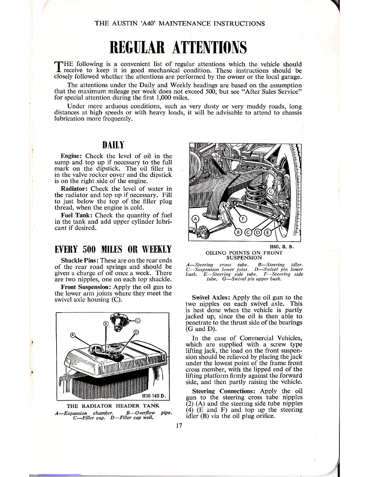
orLrNG PorNrs o* u*ãl;t'"'
SUSPENSION
Á-Steering cross tube. B-Steering idler.
C-Suspension lower joint. D-Swivel pin lower
bush. E-Steeting side tube. F-Steering side
tube. G-Swivel pin upper bush.
Swivel Axles: Apply the oil gun to the
two nipples on each swivel axle. This
is best done when the vehicle is partly
jacked up, since the oil is then able to
penetrate to the thrust side ofthe bearings
(G and D).
In the case of Commercial Vehicles,
which are supplied with a screw type
lifting jack, the load on the front suspen-
sion should be relieved by placing the jack
under the lowest point of the frame front
cross member, with the lipped end of the
lifting platform firmly against the forward
side, and then partly raising the vehicle.
Steering Connections: Apply the oil
gun to the steering cross tube nipplos
(2) (A) and the steering side tube nipples
(4) (E and F) and top up the steering
idler (B) via the oil plug orifice.
THE RADIATOR HEADER TA.NK
Á-Expansion chamber. B-Overflow pipe.
- C-Filler cap. D-Fíller caP well. t7

THE AUSTIN'A4O' MAINTENANCE INSTRUCTIONS
H?0. t88. Ã.
THE GEAR CHANGE
Á, B, C, D, E, F and J are oìling points, G is the
geatbox fller plug, and H the handbrake lever pivot
nipple.
N.B.-On no account should the
steering idler be overlooked, as lack of
lubricant in this component may cause a
serious breakdown due to the additional
load imposed on the steering box.
Wheels and Tlres: Tiehten the wheel
nuts and check the tyre pressures, includ-
ing the spare, using a tyre gauge and inflate
ifnecessary. See that all valves are fitted
wiú valve caps. Inspect the tyres for
injury and remove any flints or nails
fròm the treads. Ensure that there is no
oil or grease on the tyre, since these
substances are harmful to rubber. See
section on "Tyres" for correct pressures.
Brakes and Controls: With the oil can,
oil all the handbrake linkage points,
brake and clutch pedal linkages and
carburetter control joints. Also oil all
the gear change control joints.
THE PEDALS II7O. II3.C.
Á-Brake pedal nipple. B-Adjusting nut,
C-Muter ctlindet inlet union. D-M6tet
cyli der outlet union. E-Clutch pedal nipple.
nyERY 2,000 mHS 0n
MONTHTY
Engine: Drain the sump and refill with
new oil. Capacity is 7 pints (4 litres).
Gearbox: Check the level and top up
if necessary. For access lift the floor
carpet and remove the rubber plúg on
the right side of the gearbox covering.
The filler plug is then accessible.
Remove the plug and fill up to the
bottom of the threads. This gives the
correct level.
Clutch Pedal: With the oil gun, lubri-
cate the nipple at the base of the lever.
Brakes: Examine the brakes and adjust
if necessary. Apply the oil gun to the
brake balance lever on the rear axle, the
H40. 207, A.
THE PROPELLER SHAFT
A is the universal ioint nipple.
500 MIt[s
Engine: On new and reconditioned
engines the sump should be drained and
refilled with new oil after the first 500
miles. At the same time as these changes
are made, the cylinder head nuts should
be tested and tightened if found necessaÍy.
Gearbox and Rear Axle: After 500
miles on new vehicles, drain and refill
the gearbox and rear axle.
Always drain the oil after a run, since
it will then flow more easily. l8
Other manuals for A40 Somerset Sedan
1
Other Austin Motor Company Automobile manuals

Austin Motor Company
Austin Motor Company LANDCRAB 1993 User manual

Austin Motor Company
Austin Motor Company Austin Seven User manual

Austin Motor Company
Austin Motor Company A40 Somerset Sedan User guide

Austin Motor Company
Austin Motor Company Austin Seven User manual

Austin Motor Company
Austin Motor Company FX4R User manual


