AUSTRACK CAMPERS SAVANNAH X User manual

®
Please read owner’s manual before using the equipment. Third party component manuals
should be read in conjunction with this manual. Maintenance guidelines must be met or
exceeded, failing to meet these guidelines may result in serious injury or death and property
damage. Specication may change without notice.
©Copyright Austrack Campers 2023
USER MANUAL

Page | 1
Table of contents
Store Locator.................................................... 2
Re-sellers and suppliers .................................. 3
Rising Sun Townsville –Re-seller ............... 3
Precision Motors Armidale –Re-seller ....... 3
Redarc........................................................... 3
Projecta......................................................... 3
Truma hot water systems ........................... 3
Country Comfort hot water systems.......... 3
Dometic Air Conditioners............................ 3
Cruisemaster ................................................ 3
Ark ................................................................. 3
General Safety Introduction............................ 4
Weight Explanations........................................ 5
Load Distribution ............................................. 6
Specifications................................................... 7
Electrical System.............................................. 9
Batteries........................................................ 9
Battery charger ............................................ 9
Solar.............................................................. 9
Inverter.......................................................... 9
Mains Power ............................................... 10
Water system...................................................11
Water Pump.................................................11
Country Comfort Hot Water System ........ 12
Preparing the hot water system for use... 12
Operating the hot water system............... 14
Operating the hot water system............... 15
Braking Systems............................................. 17
Electric Brakes............................................ 17
Trailer Plug Wiring ..................................... 17
Anderson Plug............................................ 17
Trailer Breakaway...................................... 18
Handbrake...................................................18
Regular Checks................................................19
Setting up campsite....................................... 20
Stabiliser Leg.............................................. 20
Jockey wheel.............................................. 20
Camper & Canvas Care...................................21
Seasoning the canvas.................................21
Setting up the tent......................................21
Closing the camper.....................................21
Wet weather camping ................................21
Gas System ..................................................... 22
External Kitchen............................................. 23
Care Advice..................................................... 25
Troubleshooting ............................................ 26
Warranty T&C’s............................................... 28
Maintenance schedule .................................. 35
Quick Links ..................................................... 36
Austrack Academy ..................................... 36
Spare parts request form.......................... 36
Austrack Campers Blog............................. 36

Page | 2
Store Locator
Head Office
07 5498 3888
Scan for Map
Caboolture Showroom
73 Lear Jet Drive Caboolture, QLD 4510
07 5408 7111
caboolture@austrackcampers.com.au
Rocklea Showroom
7 Collinsvale Street Rocklea, QLD 4106
07 3112 7868
rocklea@austrackcampers.com.au
Newcastle Showroom
4/2364 Pacific Highway Heatherbrae, NSW 2324
02 4006 6833
newcastle@austrackcampers.com.au
Melbourne Showroom
1644 Hume Highway Campbellfield, VIC 3061
03 9357 5081
Melb@austrackcampers.com.au
Perth Showroom
634 Casella Place Kewdale, WA 6105
08 6252 7007
perth@austrackcampers.com.au
Adelaide Showroom
113-119 Morphett Road Camden Park, SA 5038
08 7009 1018
adelaide@austrackcampers.com.au

Page | 3
Re-sellers and suppliers
Rising Sun Townsville –Re-seller
35 Bowen Road Rosslea, QLD 4812
07 4779 0211
Precision Motors Armidale –Re-seller
101/107 Barney Street Armidale, NSW
02 36772 5866
Redarc
www.redarc.com.au
Technical support 1300 733 272
Projecta
www.projecta.com.au
Technical support 1800 422 422
Truma hot water systems
https://www.leisure-tec.com.au/services/
Technical support 1300 072 018
Country Comfort hot water systems
https://countrycomfortwaterheater.com.au/
Technical support 0438 242 813 or 0412 111 656
Dometic Air Conditioners
https://www.dometic.com/en-au/support/service-locator
Technical support 1800 21 21 21
Cruisemaster
https://cruisemaster.com.au/
Customer Service & Support 1300 35 45 65
Ark
https://www.arkcorp.com.au/
Customer Service & Support 02 9678 9036

Page | 4
General Safety Introduction
WARNING–Before using this product you should read this manual and
those manuals supplied by component manufacturers applicable to this
product.
This manual is supplied as a reference to required maintenance of your new Austrack Campers
Hybrid offroad camper.
Failure to use and maintain the product in accordance with what is outlined in thismanual may affect
your warranty.
Incorrect and/or insufficient maintenance may cause product failure resulting in property loss,
damage or injury or death.
Maintenance intervals are critical for normal use; extreme use may require shorter or additional
maintenance intervals. See Maintenance Schedule for more details.
This manual content does not imply, express or other any warranty, the owner should read the
Warranty T&C’s included in this manual.
Before using this product, you need to be certain that your tow vehicle is suitably rated and equipped
to tow the product safely and legally.
The trailer and vehicle pairing must we within the safe “Maximum Towing Capacity”, “Ball Weight
Capacity” and “Gross Combination Mass” as stated by the vehicle manufacturer.
This Hybrid camper is fitted with electric brakes and a “Breakaway System”. Requirements for
breakaway systems can vary from state to state. The breakaway battery draws its charge from the
house battery system of the Tanami. See Braking Systems section for more details.
Austrack Campers reserves the right to modify an advertised component (e.g., air conditioning unit,
stove, inverter) with an item of similar value and quality, due to supply and availability. In order to
fulfill orders, all Austrack Campers are subject to change at Austrack's discretion.
Page | 5
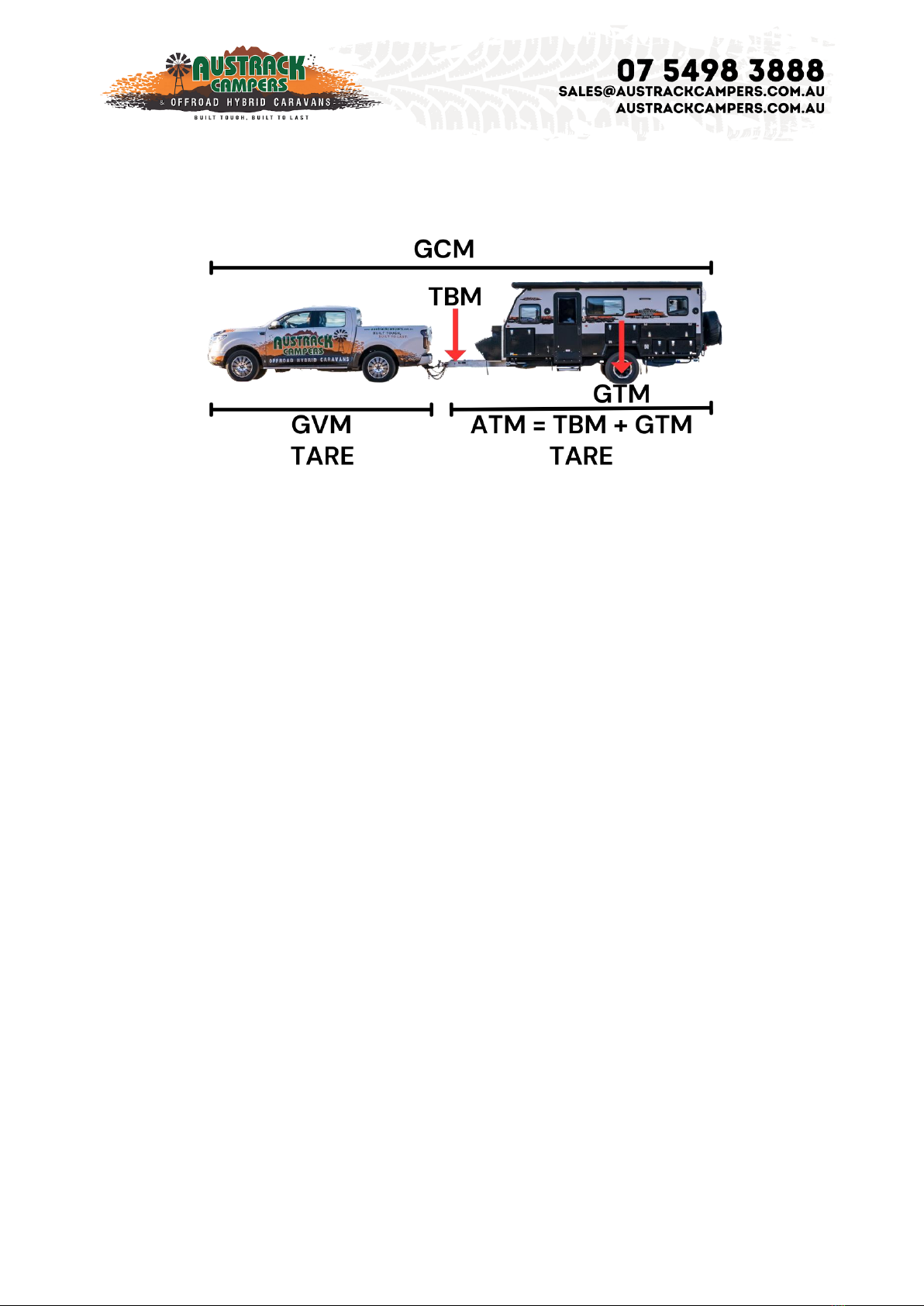
Weight Explanations
GCM Gross Combination Mass. The weight of your fully loaded vehicle and fully loaded trailer when
hitched together.
GVM Gross Vehicle Mass. This is the weight of your fully loaded vehicle.
TARE The weight of the vehicle or trailer without water, fuel or any cargo.
ATM Aggregate Trailer Mass. The maximum your trailer can weigh fully loaded.
GTM Gross Trailer Mass. The maximum weight on the axle when fully loaded.
TBM Tow Ball Mass. The weight exerted on the vehicle when hitched. This weight transfers to your
vehicle when hitched and becomes a part of the vehicles GVM.
GCM = ATM + GVM
ATM = TBM + GTM
Payload = ATM –TARE
Your Vehicle’s towing capacity is the maximum weight your vehicle can legally and safely pull when
towing, however it is also crucial to know theGross Combination Mass allowed by the towing vehicle.
State laws regulate all towing requirements, including speed limits. It's crucial to understand and
adhere to towing capacity limits for several reasons.
Exceeding these limits is both dangerous and against the law. It also places undue stress on your
vehicle's brakes and components, leading to damage and wear. Furthermore, an overweight vehicle
usually isn't covered by insurance.
When it comes to towing your camper, one of the most critical factors to consider is the tow ball
weight. This often-overlooked aspect of towing can significantly impact your safety and the handling
of your camper on the road.
A general rule of thumb is that the tow ball weight should be around 9-11% of the loaded camper's
total weight. For example, if your loaded camper weighs 3,000 kg, your ideal tow ball weight should
be between 270 kg (9%) and 330 kg (11%).

Page | 6
Load Distribution
When heading away on your next big adventure it is important to load your camper correctly to
distribute weight evenly and achieve a suitable ball weight load and prevent loading in a manner
that can cause a caravan to sway and/or roll excessively left and right. The optimum ball weight on
a caravan is between 8% and 12% of the total camper weight.
WARNING: BALL LOADING (DOWNWARD LOAD ON TOW HITCH) MUST NOT EXCEED 350KG
OR THE MAXIMUM ALLOWABLE LOAD BY THE VEHICLE MANUFACTURER OR TOW BAR RATING,
WHICH EVER IS THE LOWEST.
Exceeding these limits may result in an accident, causing property damage and/or serious injury or
death.
• Always load both sides of the camper evenly
• Load heavy items low and directly over the axle.
• Secure all items to prevent damage to the camper during travel.
• Consider water tank levels and how they may affect the balance front and back and the percentage
of ball weight.
• Heavy cooking equipment should be stored in lower cupboards.
• Tinned and bottled food for cooking etc. should be stored in the pantry drawer.
• Never load in a manner that causes the ball weight to exceed the limit of the tow vehicle.

Page | 7
Specifications
Finish • Baked enamel metallic finish with polished stainless steel trim.
Drawbar & Chassis • Fully Welded complete to rear hot dipped galvanised full RHS box drawbar 120
x 50 x 4.0mm. Full RHS box chassis 100 x 50 x 3.0mm.
Hitch • McHitch 3.5T Full Off-road Coupling. ADR approved rated safety chains. Dual rear recovery
points and bike rack holder.
Brakes • 6 stud 4x4 hubs, heavy duty parallel bearings and 12 inch heavy duty electric brakes with
mechanical handbrake.
Suspension • Heavy duty independent coil spring suspension with twin shock absorbers per
independent arm.
Jockey Wheel • Ark XO 750 Series extra heavy duty swing away dual wheel jockey wheel.
Electrical Connection • 7 pin round or 7 pin flat trailer plug, to suit your vehicle & 50 amp Anderson
Plug wired to batteries.
Electrical System • 2 x 100ah lithium batteries. 200W solar panel. REDARC 1kW Pure Sinewave
inverter. Projecta 12V 25A battery charger. Digital display amp and voltmeter. Internal and external
240V outlets. Multiple USB and accessory outlets. LED Tail lights/LED tent lights/Indicators/Number
plate lights.
Stone Guard • Fully enclosed front aluminium storage box/checkerplate stone guard.
Setup • Front & Rear 725kg self-locking winches for easy set up and gas strut assisted opening and
closing lid.
Gas & Fuel • 2 x gas bottle holders to suit 4.5 – 9kg gas bottles. 2 x 20L Jerry can holders.
Storage • Custom-made aluminium propeller plate tool box with lockable doors, double drawer
pantry storage drawers, fridge slide and space for generator with auto sensing LED lights. Rear tunnel
storage for pole and fishing rods. Stainless tie down points to top of toolbox for extra storage. Double
pinchweld seals to all openings. Fire extinguisher.
Gas Lines • Completely plumbed from gas bottles to kitchen with dual bottle change over valve and
gas certification certificate. Additional bayonet gas connection to drawbar for HWS and also
additional fitting at rear of camper for a BBQ gas supply.
Wheels & Tyres • 4 x Brand new alloy wheels with chrome wheel nuts & 4 x Brand new MT tyres 265/75
R16. Front & rear heavy duty drop down stabiliser legs & winder.

Page | 8
Water Storage • 120L Foodgrade poly underfloor water tank with aluminium tank guard & 50L
Foodgrade poly underfloor water tank with aluminium tank guard & 12v pump.
Bedding & Dining • 2 x Queen size beds with medium density foam mattress, dining area that seats 6
people.
Kitchen • Slide Out Stainless steel kitchen with drawers, electric pump, tap, large sink & AGA
approved multi burner stove. Foldaway kitchen shelving unit. Extension bench and large preparation
bench. Stainless steel wind break.
Measurements • 5200 x 1900 x 1600 mm
Tare weight (incl tent) • Approx. 1600 kg
Registered • 2250 kg trailer
Ball Weight • Approx. 140 kg
VIN plate • all ready for registration

Page | 9
Electrical System
Batteries
The Savannah is fitted with 2 x 100 Ah Lithium Iron Phosphate Batteries. These batteries have an
integrated BMS to prevent accidental damage to the batteries. Included is an activation cable, should
the battery become discharged at or below 10 V, connect the camper to a power source and press
the button on the activation cable to awaken the batteries. It is only required to activate one battery,
and this will awaken both.
Battery charger
The Savannah comes fitted with the Projecta 25 A battery charger. This is solely a 240 V charger; it
will only work when the camper is plugged into shore power. It will come preset, there is no need to
change the settings in the charger.
For all charger instructions, please see the manual in your camper or here
https://www.projecta.com.au/products/IC25/intellicharge-25a-bat-chgr
Solar
The Savannah comes with a 200 A free standing solar panel. This is designed to plug into the
Anderson plug on the drawbar. It has a built-in solar regulator and is plug and play.
There is a circuit breaker for the Anderson connection in the rear cupboard, above the water tank
change over valve. If the solar panel does not recognise or charge the batteries, check this breaker
to ensure that it has not tripped.
Inverter
The Savannah is fitted with a Redarc 1000 W pure sine wave inverter. This inverter is connected to
the 240 V power points inside your van and the one near the kitchen externally. The inverter needs
to be manually switched on and off, using the switch on the side. The switch needs to be positioned
upwards in the I position for the inverter to work. The off position is the middle or O.

Page | 10
When using the inverter, especially with high wattage appliances there will be a temporary drop in
the voltage of your batteries, this is due to the high current being drawn by the system. This will
increase back to normal once the appliance has been switched off.
When not in use, the inverter should be switched off. The inverter will draw current off the batteries,
even if not supplying power to a 240 V appliance, and this can cause your batteries to become flat if
there is not sufficient charge being supplied to the camper.
Mains Power
The Savannah comes standard with a 15 A input on the side of the camper to allow mains power to
be connected directly to the electrical system. This 15 A input has a larger earth connection than a
standard home plug and requires the use of a specialised 15 A extension lead which will have the
larger earth pin on both ends. If connecting the van to mains power point where a 15 A power point
is not available, you must use a 10 A -15 A adaptor with safety switch. These are available from most
camping or hardware stores.
The RCD safety switch for the 240 V circuits is located on the outside of the club lounge.
240 V mains power is lethal, failing to use an adaptor can result in serious injury or death.

Page | 11
Water system
The Savannah is fitted with 1 x 160 L and 1 x 50 L fresh water poly tanks with stainless steel guard.
Both tanks have bungs and taps on the bottom for the tank for easy draining and rinsing.
The water tanks are not interconnected, you can change between the tanks by rotating the handle
in the rear compartment 180°. The rule of thumb with this handle is that the blue will point the
opposite direction to the tank that the water is being drawn from. This means if the handle is pointing
to the rear of the camper, you are drawing water from the front tank. It is recommended to drain one
tank before switching to the other, and not to draw from both tanks at the same time.
Each of the water tanks require filling independently. The rear water tank filler is closer to the rear of
the trailer and the front tank filler is in front of the wheel arch. The filler is equipped with a breather
hole which will allow the air to escape the tank while the water is going in. If this hole is blocked,
water will not be able to enter the tank. The tank is full when water comes out of the breather hole.
The camper does not have a grey water tank fitted, please follow all instructions from Caravan Park
management/National Parks officers regarding the management of grey water.
Water Pump
The water pump will need to be switched on using the push button on the control panel. It may make
a noise when initially turned on with all taps closed to pressurise the system, but this should shut off
quickly. If the pump continues to run with all taps closed, this can indicate a leak and requires
investigation and rectification.
The water pump will automatically turn on when a tap is opened and will shut off shortly after the
tap is closed. It may turn on and off quickly a few times to fully pressurise the system, this is totally
normal.
If the water pump is cycling on and off and the system has been thoroughly inspected for leaks with
nothing found, please contact the service department for more instructions.
Page | 12
Country Comfort Hot Water System
The Savannah camper comes with the Country Comfort portable LPG hot water system as a standard
inclusion. This is designed to work with the gas and water fittings on the drawbar of the camper to
provide a hot shower for use in the ensuite.
The Country Comfort hot water system is activated by water pressure, without water pressure it will
not operate. You need to ensure that the water tank being drawn from is full enough to provide a
consistent flow of water to the hot water system.
Full user manual and instructions can be found in the box or here,
https://countrycomfortwaterheater.com.au/collections/shower-packages/products/country-
comfort-portable-lpg-water-heater
Inside the hot water system box you will find hoses and fittings to connect the hot water system to
the water connection on your drawbar. There will not be a gas hose inside the box, the hose required
to connect the hot water system is in the draw under the stovetop of your slide out kitchen.
All adjustments and maintenance must only be carried out by an authorised person. The
installation of all gas and combustions appliances MUST comply with the standards in force.
Carbon Monoxide warning - This appliance is designed for outdoor use only and must be used
in well ventilated areas. Use in enclosed areas, including inside the camper annex, may result in
injury or death.
Accessible parts of the Country Comfort hot water system may be very hot, keep young
children away.
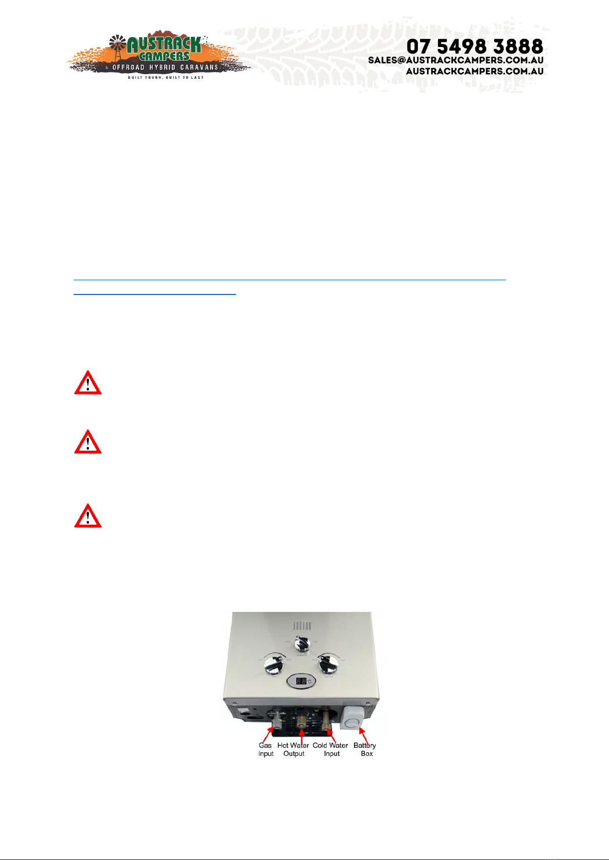
Preparing the hot water system for use
1.Remove the heater along with all the components from the box and place them on a table in front
of you. Notice that there is a gas input, hot water output, cold water Input as well as a battery box.
Page | 13
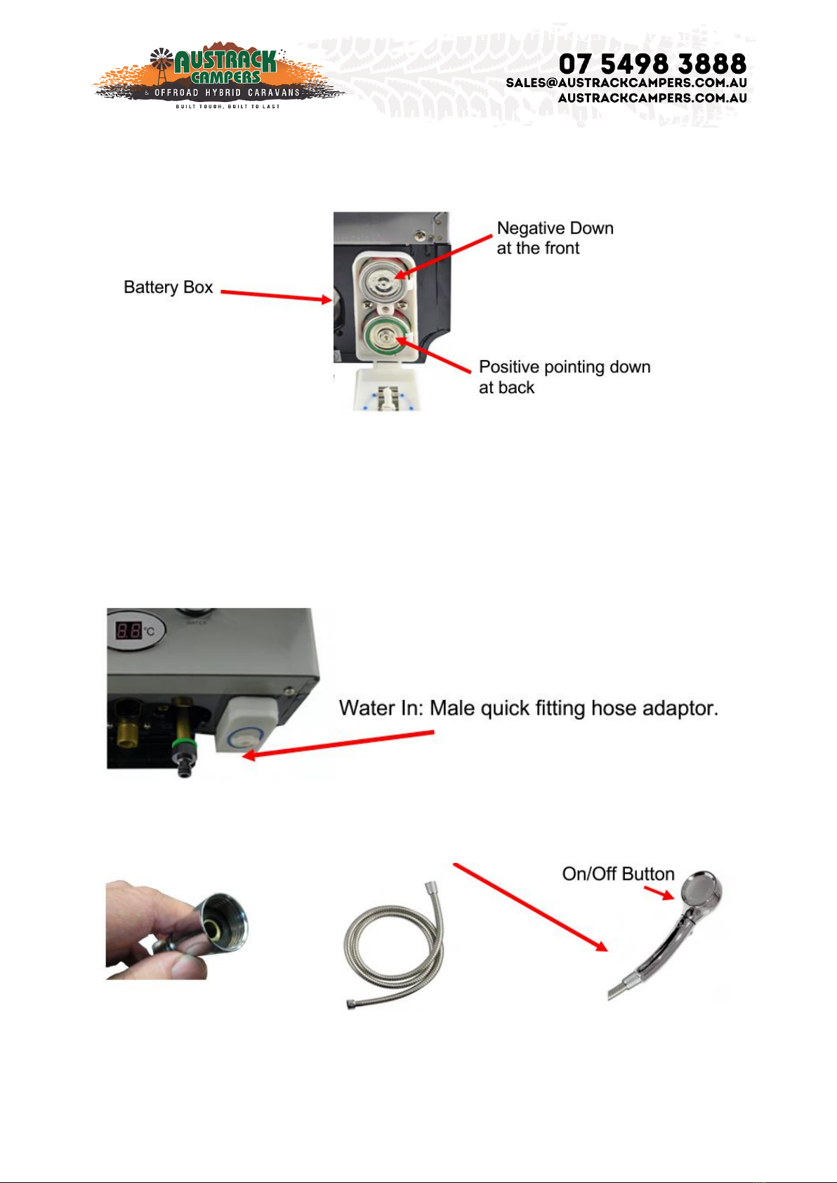
2. Insert two ‘D’ batteries into the ‘battery box’ and close the battery box lid. Note: The orientation of
the battery terminals. Positive down at the back. Negative down at the front.
For garden hose water supply use, install a male garden hose attachment to allow for a ‘snap on’
connection (not supplied) to a garden hose. First, install a reducer fitting to increase the ‘water
input’ size from ½” to ¾” to suit the ‘quick fitting’ attachment. Male quick fitting hose adaptor
(supplied)
3. Wrap the ‘water input’ thread with two rotations of Teflon tape before installing the reducer
fitting. Tighten the adaptor, taking care not to over tighten as this could break or crack the inlet
pipe. Finally, connect the male garden hose attachment.
4. Shower hose and rose: Check that the seal is secure in both ends of the flexible shower hose.
Attach the shower rose to the flexible shower hose using the conical end fitting. Hand force only. Do
not over tighten.
Page | 14
Operating the hot water system
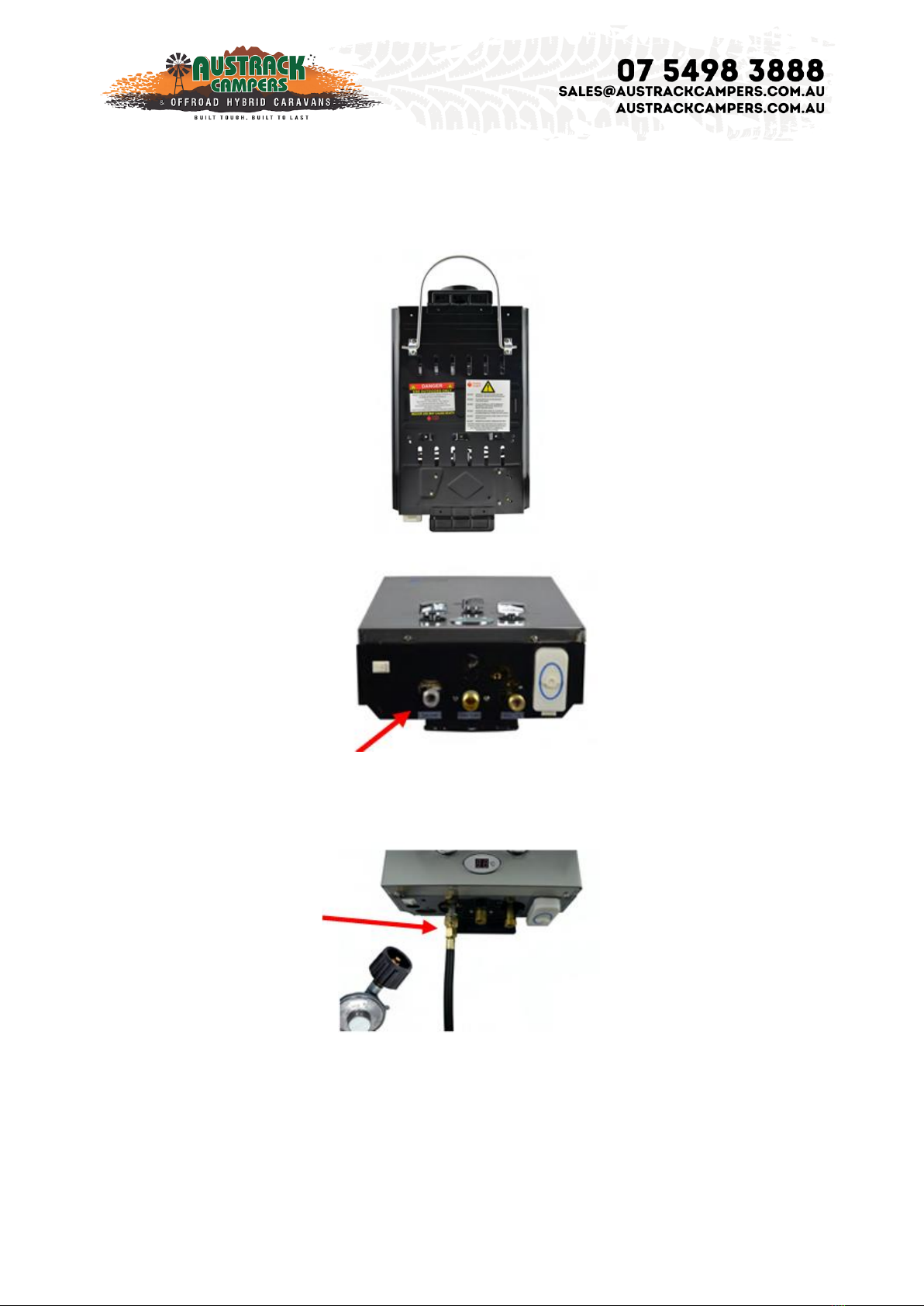
1. Hang the appliance on a suitable vertical surface by the top hanger attached to the back
cover of the heater.
2. The ‘gas inlet’ will be used to connect to the gas hose regulator.
3. Attach the flexible gas hose and regulator to the ‘gas inlet’. Slowly using two (2) spanners,
tighten this connection, taking care not to over tighten as doing so may damage the pipe.
DO NOT OVERTIGHTEN.
The hot water system is ready to connect to the water hoses.

Page | 15
4. Attach to other end of the flexible shower hose to the “water OUT connection (middle
connection) on the water heater. Do not over tighten. Note that you can also apply Teflon
tape to this threaded connection to avoid leaks.
5. Connect the bayonet end of the gas hose to the bayonet fitting on the drawbar and turn on
the gas cylinder.
Operating the hot water system
1. It is preferable to set the BURNER control to LOW
2. IMPORTANT: It is important that when starting the appliance that the gas regulator is set to
the ‘min’ position.
3. IMPORTANT: It is important that when starting the appliance that the water regulator is set
to the ‘min’ position.

Page | 16
4. Switch LPG Water Heater ON using the rocker switch located at the bottom on the LPG
Portable Water Heater. Do this by having the red dot pushed in.
5. Ensure that the button on the shower rose is in the “Off” position.
6. Open the valve for your input water source. This can come from your 12v pump or mains
supply. When ready push the button “On” your shower rose. Water should start to flow
through the shower unit.
7. Note: You should hear a series of clicks and then the burner should ignite. The burner flame
can be seen operating through the ‘viewing window’ located at the front of the appliance.
8. Adjust the temperature of the water flowing from the showerhead by turning the ‘gas
regulator’ and ‘water regulator’ knobs.
Note: For higher temperatures, increase the gas regulator control and decrease the water regulator
control. Switching the BURNER control from LOW to HIGH will increase the temperature further.
A temperature in excess of 50°C will activate the Over Temperature Safety Sensor and will
shut down the burners. To relight the burners, you will need to turn the water flow OFF and then
back ON.
Page | 17
Braking Systems
Electric Brakes
The Savannah comes fitted with electric brakes which require a brake controller installed into the
towing vehicle that can be controlled from the driver’s seat. There are many systems available
which can either be permanently installed into the tow vehicle or Bluetooth units that are mounted
to the trailer and have a remote to control from the driver’s position. You must have a brake
controller installed in the vehicle or a Bluetooth unit on the day of handover otherwise the camper
will not be released to you.
Electric trailer brakes are designed to assist your vehicle brakes to stop in a safe and effective
manner. It is important that both your vehicle and the trailer are serviced regularly. The trailer
brakes will have a run-in period that will vary trailer to trailer, but it is important to have the trailer
brakes inspected and adjusted by a qualified professional in line with the maintenance schedule.
During your regular services, a qualified professional will complete a visual inspection of the brake
shoes to determine if they require replacement. Replacement will be necessary when the lining is
worn down to approx 1.5mm, or abnormally scored or gouged.
Scouring and gouging of the brake shoe lining is generally due to overheating of the brake system or
dirt caught in between the shoe and the hub. It is important to ensure that the brakes are adjusted
correctly and cleaned thoroughly after each trip, especially if there were water crossings involved.
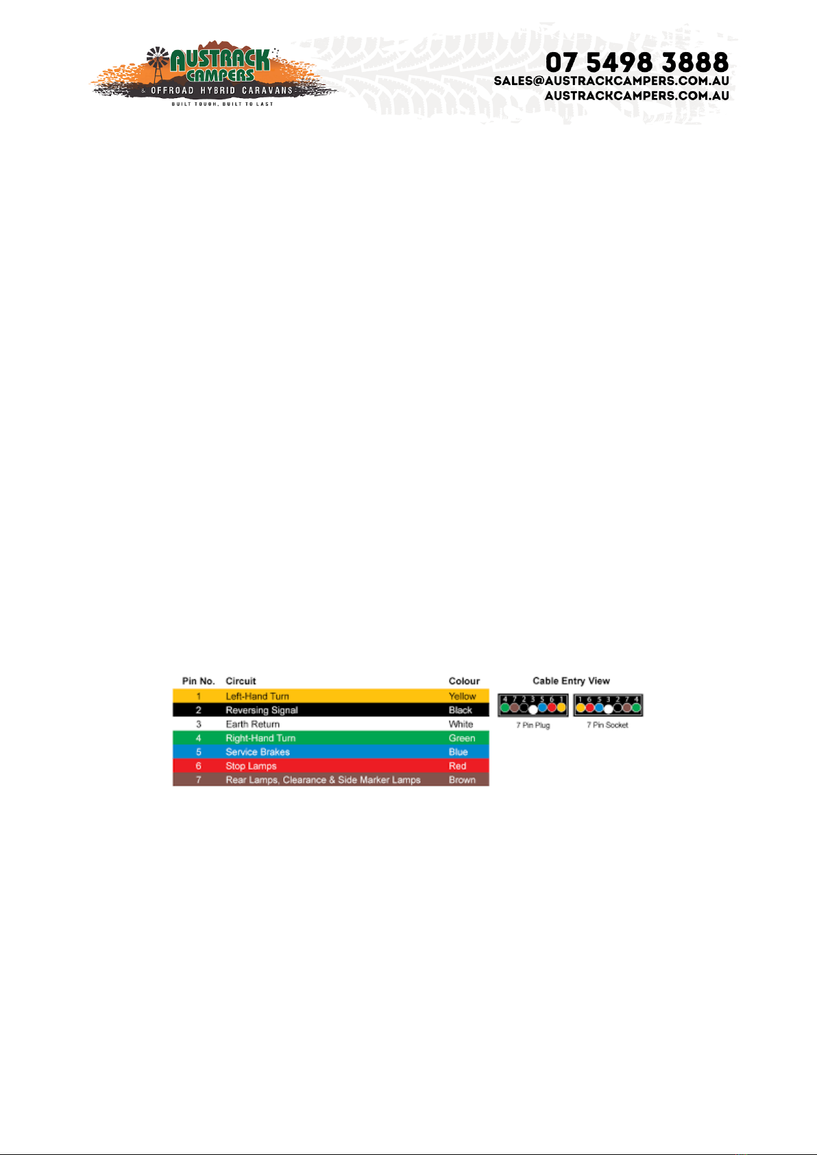
Trailer Plug Wiring
The Savannah comes fitted standard with a 7-pin flat trailer plug.
If a different plug configuration has been requested, please reach out to your local showroom or
the service department to obtain a copy of the wiring diagram.
Anderson Plug
The Savannah is fitted with an Anderson connection at the drawbar. This is wired directly to the
batteries through a circuit breaker inside the water tank change over compartment. This is designed
to run all regulated sources of charging to the batteries and can also be utilised as a power output if
required.
To adequately charge from your vehicle, you will need to have a DC-DC charger installed into your
vehicle. Without this, you will receive some charge, but it will rarely be enough to charge the batteries
to capacity.

Page | 18
Trailer Breakaway
The Savannah comes fitted with a Breakaway switch. The steel cable attached to the drawbar
switch is designed to attach to a solid part of your vehicle. In the event of a trailer disconnection,
this will pull out the pin from the switch and activate the trailer brakes. The brakes will stay locked
on as long as the pin is removed from the drawbar switch and there is power in the battery system
of the camper. It is important that the breakaway cable is not attached to the tow bar, but instead
to the vehicle itself, in the event the tow bar comes loose.
The breakaway system has a battery fitted under the seat of the Savannah; this is designed to supply
the breakaway system with power to lock the brakes on for at least 15 minutes when the pin is
removed from the drawbar switch. The breakaway battery charges from the house batteries fitted to
the camper, and as such will always show a charging light on the control box. When the test button
is pushed, it should display a green light. If any other light is displayed, please contact the service
department for more advice.
Do not use the breakaway system as an alternative to the handbrake or remove the pin from
the breakaway switch as an anti-theft measure, this will cause a rapid discharge of your house
batteries. This will leave your camper without power and can cause damage to the batteries.
Handbrake
The handbrake is operated mechanically by means of a cable. The cable attaches to the backing
plate and when the handbrake is applied the cable creates a force on the primary and secondary
brake shoe. This causes them to spread until they make contact with the brake drum surface.
The cable adjuster needs to provide enough tension that the handbrake is 1/3 raised when the
camper is unloaded. Once the camper is loaded, test and adjust if necessary. Insufficiently adjusted
handbrake will still allow the camper to move when the handbrake is fully raised.
It is very important to always use wheel chocks and levelling ramps, do not rely solely on the
handbrake even if on a level surface.
To adjust the handbrake, there is an adjuster attached to the cable at the drawbar. To tighten the
handbrake, loosen off the nut and turn the adjuster wheel in a clockwise direction. Ensure that the
nut is re-tightened after the adjustment. Overtightened handbrakes can cause the brake shoes to
drag on the inside of the drum, causing permanent damage.

Page | 19
Regular Checks
Wheel Nuts
Wheel nuts should be checked on a regular basis usings a torque wrench and tightened to 140 Nm.
It is not recommended to use a rattle gun, as there is no way to know how tight the nuts are.
Overtightening will damage the studs and will cause them to fail prematurely. Under tight wheel
nuts will cause vibration of the wheel and will eventually cause the studs or nuts to fail.
Initially, you will need to check the wheel nuts at 50kms, 100kms, 250 kms and 500kms, and then
regularly after that. during travel on especially bumpy or corrugated roads, the wheel nuts will
need to be checked more often.
Hitch
The bolts securing the hitch to the trailer are a high tensile bolt and should be tightened to 180 Nm.
These bolts should be checked with a torque wrench every 2500 –5000kms, depending on the
road conditions.
Suspension bolts
The suspension bolts should be visually inspected daily to make sure they have not moved. They
should otherwise be serviced as per the maintenance schedule. These bolts should be tightened to
180 Nm.
Other manuals for SAVANNAH X
1
Table of contents


