Australian Off Road PowerCore 30 User manual

POWERCORE 30 OPERATOR MANUAL
1
PowerCore 30
b a t t e r y m a n a g e m e n t s y s t e m
The PowerCore30 is a revolutionary total battery management and automation
system developed specifically for 4wd vehicles, RV's and campers. With powerful,
compact all in one features, the system will deliver a full continuous 30 Amps of
charging power from solar panels, vehicle DC to DC input and AC power. It will
manage dual battery systems, disconnect loads when batteries are low, and
maintain house and start batteries during storage. View and control the
PowerCore30 from it's remote touch screen control panel, or download the
PowerCore30 app and connect your smart phone.

POWERCORE 30 OPERATOR MANUAL
2
FEATURES
ALL IN ONE compact 30 amp charger
AC CHARGE - Charge from AC power source 30 amps
DC_DC CHARGE - Charge from DC - DC vehicle power source 30 amps
MPPT SOLAR CHARGE - Charge from Solar panel source via MPPT 30 amps
IGN input for DC - DC SMART Alternator charging
Automation loads output disconnect on low voltage state
Dual battery system manager with vehicle mode charging
Touch screen operation, with full charger control from remote panel
WIFI connection for app control
Tank Monitor option to monitor up to 5 x tanks using the FinScan PRS1000 RV
tank sensor or RV Electronics Sensor
LITHIUM and AGM charge profiles
RV Automation - switching of up to 8 outputs with resettable fusing , including
dimming of lights ( Outputs 4 to 8 bank switched )

POWERCORE 30 OPERATOR MANUAL
3
SWITCHING OPERATION
All switching of lights and 12vDC power circuits ( with the exception of the
dimming lights ) are operated and accessed via the switching icon from the home
page
Turning any light or power circuit on and off, is performed via the blue rectangle
buttons :
12V POWER BUTTON - Blue indicates the circuit is turned OFF
12 POWER BUTTON - Orange indicates the circuit is turned ON

POWERCORE 30 OPERATOR MANUAL
4
DIMMING OPERATION
The PowerCORE has a dimming feature and is usually connected to an interior
light to allow the operator to set the light level in the living space. Dimming can
be accessed using the dimming icon from the home page.
There are 5 levels of light intensity ( dimming ) available. Level 0 turns off the
light, and Level 5 will turn on the light at full brightness.
ON BUTTON - pressing the ON button will set the light level to 5
OFF BUTTON - pressing the OFF button will set the light level to 0
UP ARROW - pressing UP arrow will increase the light intensity by 1
Down Arrow - pressing down arrow will decrease the light intensity by 1

POWERCORE 30 OPERATOR MANUAL
5
STORAGE MODE
Storage mode is a feature that can be used when a camper or RV is put into
storage. To turn storage mode on, press the Storage mode button on the home
screen. To Turn storage mode off, press the button again so that it stops flashing.
When storage mode button is pressed on, the Storage mode button will :
1. Begin to flash
2. Automatically turn off all outputs on PowerCORE and any expansion power
modules on the system. All power will be turned off.
3. After 5 minutes the system will enter sleep mode where PowerCORE will turn
off power to any connected modules to preserve power during storage. This will
include loss of power to the touch screen. It is important that long term storage
will require a power source connected to PowerCORE. PowerCORE power
consumption in storage mode is minimal, however, over a long period of time in
storage, the battery will eventually be discharged to a damaging state.
IMPORTANT : when the PowerCORE has entered sleep mode, any input source
connected such as 240v or Sunshine on the solar panels will wake the system, and
turn the screen on. With an input mode source left connected, the screen will
remain powered, even whilst in storage mode.

POWERCORE 30 OPERATOR MANUAL
6
LITHIUM BATTERY JUMP START FEATURE
A characteristic of some Lithium batteries, is that they will have their own internal
battery management system. When a Lithium battery is excessively discharged,
the internal battery management system will disconnect the battery terminals to
preserve the battery and protect it from damage.
The PowerCORE has a unique automatic jump start feature built in that will
automatically bring back lithium batteries into operation, without external "Jump
Starting" required. To engage the LBJ feature, simply connect any power source to
PowerCORE and the disconnected Lithium battery will start up and begin taking
charge from PowerCORE.
CHARGING OPERATION
The PowerCORE30 battery management system will manage all aspects of
keeping your batteries in the best charged state possible. It will automatically
select between charge sources available to continue charging. Charging
information and battery state are relayed to the touchscreen for viewing.
CHARGE SOURCES
There are three charging sources connected to the PowerCORE. The PowerCORE
will provide up to 30 Amps of charge from the selected source.
On the PowerCORE battery page, the selected charge source will be indicated by a
flashing white icon. Only one selected source will be selected at any given

POWERCORE 30 OPERATOR MANUAL
7
moment in time , regardless of availability of multiple sources to the PowerCORE.
All other source icons will be grayed out.
SOLAR source - represents charging from solar panels
VEHICLE source - represents charging from the vehicle alternator
MAINS 240V source - represents charging from the Mains 240v
CHARGE PRIORITY
The PowerCORE is internally programmed to prioritize selection of multiple
available charge sources in the following order of priority to enable the fastest
charge time possible :
1. MAINS 240V
2. VEHICLE
3. SOLAR

POWERCORE 30 OPERATOR MANUAL
8
GREEN MODE
In addition to the default charge priority, a "Green Mode" feature is available on
the battery page . Green mode will change the charging priority to select Solar as
the first priority. This will change the behavior of PowerCORE to always attempt
to provide charging from solar power first , if available.
GREEN MODE OFF GREEN MODE ON
CHARGE MODES
The PowerCORE will charge in 3 modes indicated below :
NO SOURCE - No source icon will appear when there is no charge
source available for charging
BULK MODE - bulk mode icon will appear when the charger is
charging a relatively discharged battery, and High
current is being drawn from the charger.
ABSORPTION - absorption mode icon will appear as the battery
becomes more charged and reduces the amount of
current that it draws from the charger.
FLOAT - float mode icon will appear when the battery reaches its
charged state. Float mode also reduces the output of the
charger to a lower voltage of 13.7 volts to maintain the
batteries charge, without overcharging the battery for
long periods of time.
POWERCORE 30 OPERATOR MANUAL
9
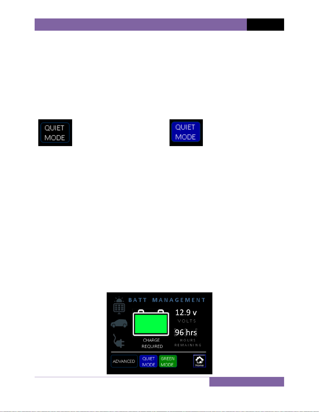
QUIET MODE
Quiet mode will reduce the speed of the PowerCORE cooling fan. This will reduce
noise during operation for situations where PowerCORE is installed in an interior
cavity. In extreme cases where ambient air temperature is high, and PowerCORE
is operating at full capacity to charge a heavily discharged battery, PowerCORE
may over ride Quiet mode temporarily.
QUIET MODE OFF QUIET MODE ON
BATTERY MODE
Battery mode is set when the batteries are installed. The battery mode icon will
show either " LITHIUM" or "AGM"
CHARGING DATA
There are two pages available to view for battery data, BASIC and ADVANCED
screens.

POWERCORE 30 OPERATOR MANUAL
10
The BASIC screen will show information that is required to determine the battery
state, at a glance. Information presented :
1. Charge source
2. State of Charge
3. Voltage
4. Hours of use remaining
The ADVANCED screen will show more detailed battery data of a more technical
nature. Information presented :
1. Charge source
2. State of Charge
3. Voltage
4. Battery Amps - reported by Current Shunt module as NET amps
5. Charger Amps - charging amps output from PowerCORE charger
6 Amp Hours Used
7. Hours of use remaining

POWERCORE 30 OPERATOR MANUAL
11
ERROR MESSAGES
Error warnings displayed on the battery page will relate to the charging ability of
PowerCORE.
LOW VOLTAGE WARNING
LOW VOLTAGE WARNING - The low voltage warning icon will appear
when the battery voltage drops below a set
threshold. By default the battery low
voltage warning will appear when the
battery voltage drops below 11.5v .
When a charge source is applied and
battery charging resumes, the low voltage
warning icon will reset when battery
voltage exceeds 12.0v.
NOTE : Power outputs will also attempt to
turn off when in low voltage state to help
preserve the life of the battery.
BATTERY TEMPERATURE - The battery temp warning icon will appear
if the battery temperature sensor mounted
on the positive terminal of the battery
terminal, detects a temperature of greater
than 60 degree's Celsius. PowerCORE will
stop charging the battery if the battery
temperature icon appears. Charging will
resume when the battery cools.

POWERCORE 30 OPERATOR MANUAL
12
NOTE : it is strongly recommended that
your batteries be tested if you regularly
have the battery temperature icon appear.
OVER TEMPERATURE - The over temperature icon will appear if
PowerCORE has reached a temperature that
is too high to continue operating.
PowerCORE will stop charging while it cools
itself back to an acceptable temperature
before resuming charging. The over
temperature icon will disappear and
charging will resume automatically. The
over temperature icon does not represent a
faulty state of the charger. Over
temperature may occur for many reasons :
1. PowerCORE is installed in a tight sealed
cavity with restricted airflow.
2. Your current location has a very warm
ambient air temperature.
3. You have a large battery bank capacity
that is heavily discharged and requires an
extended period of charging at full charger
capacity.
OVER CURRENT - The over current error message will appear
when the Charger battery amps exceeds 35
amps. Over current warnings will usually be
caused by an incorrect grounding system.

POWERCORE 30 OPERATOR MANUAL
13
OVER VOLTAGE - The over voltage error message will appear
when PowerCORE detects that the battery
voltage has exceeded 17.8 volts.
PowerCORE cannot supply a voltage greater
than 14.4 volts.
TANK MONITORING
The PowerCORE screen also monitors up to 5 x tanks, Depending on
configuration, 2 to 5 tanks may appear.
The tank monitoring page can be accessed by pressing the TANK button from the
home screen
When accessing the tank screen, PowerCORE will apply power to the tank sensors
and take a reading to show in the tank gauges. This process can take up to 4
seconds and is designed to preserve valuable battery power when the tanks are
not being viewed. Each tank is a bar graph indicating the tank level.
TANK EMPTY TANK FULL

POWERCORE 30 OPERATOR MANUAL
14
SYSTEM OVERIDE
In the event of a system failure, there are mechanisms on the PowerCORE system
to allow you to bypass the controls and apply emergency power to allow you to
continue operating connected DC loads.
POWERCORE OVERIDE
Located at the large green connector end of the charger, press the "Overide"
toggle switch to the ON position. This will turn on power to all outputs connected
to the PowerCORE switching connector.

POWERCORE 30 OPERATOR MANUAL
15
EXPANSION MODULE OVERIDE
Located inside the expansion module, unscrew the plastic lid to reveal the fuses
located inside. By moving the fuses for each circuit, the expansion module acts as
a simple fuse box and applies fuse protected power to the connected DC load for
emergency power.
Bypass circuits . Move fuses here
in case of emergency to supply
power to connected DC loads.

POWERCORE 30 OPERATOR MANUAL
16
SPECIFICATIONS
AC Input voltage range
220 - 240vAC - 50-60Hz
Output Current
30 amp continuous
Charge voltage
14.4v
Float voltage
13.7v
DC - DC Input voltage
9 -28v DC
Solar Input
9 - 32v DC
Cooling
Quiet Thermal / Speed controlled fan
Over temperature shutdown
Yes
Operating temperature
-30°C to 50°C
Short circuit protection
Yes
Memory store on disconnect
Yes
USB data logging
Yes - Optional
Automation Output 1 - digital switching
Lights - with built in dimming - 15A max
Automation Output 2 - digital switching
DC - 12A max
Automation Output 3 - digital switching
DC - 12A max
Automation Output 4 - digital switching
Bank switch Outputs 4 to 8 - 8A max each
Automation Outputs protection
Auto reset fuse - internal
Remote control and monitoring
Yes - WIFI connection via Android or iOS
Compliance
Safety - IEC60335-2-29 EMC - RCM-5533
Table of contents


